Note: Descriptions are shown in the official language in which they were submitted.
CA 02210411 1997-07-14
VISCOUS FLUID HEATER
BACKGROUND OF THE INVENTION
1. FIELD OF THE INVENTION
The present invention relates to viscous fluid heaters,
and more particularly, to heaters having a heating chamber
and a heat exchanging chamber accommodated in a housing with
viscous fluid and a rotor accommodated in the heating
chamber. Heat exchange takes place between the heat
generated in the heater when the rotor shears the viscous
fluid and a circulating fluid flowing through the heat
exchanging chamber.
2. DESCRIPTION OF THE RELATED ART
Viscous fluid heaters, which are operated by the drive
force of automobile engines, have become widely used as an
auxiliary heat source. Japanese Unexamined Patent
Publication No. 2-246823 describes a typical viscous fluid
heater incorporated in a vehicle heating apparatus.
The viscous fluid heater has a front housing and a rear
housing which are coupled to each other. A heating chamber
is defined in the front and rear housings while a water
jacket (heat exchanging chamber) encompasses the heating
chamber. A drive shaft is rotatably supported by a bearing
in the front housing. A rotor is fixed to one end of the
drive shaft in the heating chamber. Thus, the rotor and the
drive shaft rotate integrally. Rib-like projections are
provided on the front and rear surfaces of the rotor and the
--1--
CA 02210411 1997-07-14
opposed inner walls of the heating chamber. The opposed
projections are aligned to one another so as to form
labyrinth grooves. Furthermore, the opposing projections
are spaced from each other so as to form a labyrinth-like
clearance between the outer surfaces of the rotor and the
inner walls of the heating chamber. A predetermined amount
of a viscous fluid, such as silicone oil, is contained in
the heating chamber. The viscous fluid also fills the
labyrinth-like clearance.
When the drive force of the engine is transmitted to
the drive shaft, the drive shaft rotates together with the
rotor in the heating chamber. The viscous fluid between the
inner walls of the heating chamber and the outer surfaces of
the rotor are sheared by the rotation of the rotor. This
results in fluid friction and produces heat. Heat exchange
occurs between the heating chamber and the coolant
circulating through the water jacket. The heated coolant is
then sent to an external heater circuit to warm the
passenger compartment.
The prior art viscous fluid heater described above
requires the rib-like projections to be formed on the front
and rear surfaces of the rotor to form the labyrinth
grooves. Accordingly, a rotor body is disk-like and the
axial length of the body is shorter than the radius of the
body. In such a rotor, the main shearing surface
corresponds to the rib-like surfaces provided on the front
and rear surfaces of the rotor. Furthermore, the rotating
speed (i.e., shearing speed) of the rib-like projections
becomes higher at positions located farther from the axis of
the rotor body. Thus, it is necessary to enlarge the rotor
CA 02210411 1997-07-14
diameter, that is, the outer diameter of the rotor body, to
increase the heating value of the heater. However, space,
and especially, space in the engine room, is limited. Thus,
if the radius of the viscous fluid heater is large, it is
difficult to provide sufficient space for the heater in the
engine room. Furthermore, a large viscous fluid heater
affects the layout of other equipment in the vehicle.
SUMMARY OF THE INVENTION
Accordingly, it is an objective of the present
invention to provide a viscous fluid heater that maintains
constant heating value and facilitates installation in
vehicles or the like.
It is a further objective of the present invention to
provide a viscous fluid heater that has a superior heating
ability and that copes with the problems caused when
altering the basic shape (or dimension) of the rotor and the
heater body.
To achieve the above objective, the present invention
provides a viscous fluid heater including a housing for
accommodating a heating chamber and a heat exchanging
chamber. Viscous fluid is contained in the heating chamber.
Circulating fluid circulates through the heat exchanging
chamber. A rotor is located in the heating chamber. The
rotor rotates to shear the viscous fluid in the heating
chamber and thus generate heat. The circulating fluid
exchanges heat with the heated viscous fluid in the heating
chamber. A reservoir chamber is defined within the rotor to
reserve the viscous fluid.
CA 02210411 1997-07-14
Other aspects and advantages of the invention will
become apparent from the following description, taken in
conjunction with the accompanying drawings, illustrating by
way of example the principals of the invention.
BRIEF DESCRIPTION OF THE DRAWINGS
The features of the present invention that are believed
to be novel are set forth with particularity in the appended
claims. The invention, together with objects and advantages
thereof, may best be understood by reference to the
following description of the presently preferred embodiments
together with the accompanying drawings in which:
Fig. 1 is a cross-sectional view showing a viscous
fluid heater according to a first embodiment of the present
invention;
Fig. 2 is a cross-sectional view showing a viscous
fluid heater according to a second embodiment of the present
invention;
Fig. 3 is a cross-sectional view showing the main
portion of a viscous fluid heater according to a third
embodiment of the present invention;
Fig. 4 is a cross-sectional view showing the main
portion of a viscous fluid heater according to a fourth
embodiment of the present invention; and
Fig. 5 is a cross-sectional view showing the main
portion of a viscous fluid heater according to a fifth
CA 02210411 1997-07-14
embodiment of the present invention.
DETAILED DESCRIPTION OF THE PREFERRED EMBODIMENTS
A viscous fluid heater, which is incorporated in a
vehicle heating apparatus, according to a first embodiment
of the present invention will now be described with
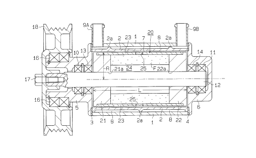
reference to Fig. 1. As shown in Fig. 1, the viscous fluid
heater of the first embodiment has a housing that is
constituted by a cylindrical intermediate housing 1, a
cylinder block 2, a front housing 5, and a rear housing 6.
The housing is fixed on an engine (not shown) of the
vehicle.
The cylinder block 2, which is substantially
cylindrical, is pressed into the intermediate housing 1. A
rib 2a extends helically along the peripheral surface of the
cylinder block 2. The front ends of the intermediate
housing 1 and the cylinder block 2 are coupled to the front
housing 5 with a gasket 3 arranged in between. The rear
ends of the intermediate housing 1 and the cylinder block 2
are coupled to the rear housing 6 with a gasket 4 arranged
in between. A heating chamber 7 is defined in the cylinder
block 2. Accordingly, the cylinder block 2, the front
housing 5, and the rear housing 6 constitute a partitioning
member, which defines the heating chamber 7 in the housing.
When the cylinder block 2 is pressed into the
intermediate housing 1, the helical rib 2a on the peripheral
surface of the cylinder block 2 abuts against the inner wall
of the intermediate housing 1. A water jacket 8, which
serves as a heat exchanging chamber, is defined in the space
CA 02210411 1997-07-14
between the peripheral surface of the cylinder block 2 and
the inner surface of the intermediate housing 1.
An inlet port 9A is provided at the front of the
intermediate housing 1. Coolant, which serves as a
circulating fluid, circulates between a vehicle heater
circuit (not shown) and the water jacket 8 through the inlet
port 9A. An outlet port 9B is provided at the rear of the
intermediate housing 1. The coolant is sent out from the
water jacket 8 to the heater circuit through the outlet port
9B. In the water jacket 8, the rib 2a serves as a means for
guiding the circulating fluid and provides a helical
circulation passage for the circulating fluid that flows
from the inlet port 9A to the outlet port 9B.
Bearings 10, 11 are provided in the front and rear
housings 5, 6, respectively. The bearings 10, 11 rotatably
support a drive shaft 12. An oil seal 13 is provided in the
front housing 5 adjacent to the heating chamber 7. An oil
seal 14 is provided in the rear housing 6 adjacent to the
heating chamber 7. The middle portion of the drive shaft 12
in the heating chamber 7 is arranged between the oil seals
13, 14. Thus, the oil seals 13, 14 seal the interior space
of the heating chamber 7. In the heating chamber 7, a rotor
20 is fixed to the drive shaft 12 and supported so as to
rotate integrally with the shaft 12.
The rotor 20 includes a pair of fixed plates 21, 22,
which are made of aluminum alloy, and a cylindrical member
23. Openings 21a, 22a extend through the center of the
fixed plates 21, 22, respectively. The drive shaft 12 is
inserted through the openings 21a, 22a. The fixed plates
CA 02210411 1997-07-14
21, 22 are spaced with a predetermined interval therebetween
in the heating chamber 7 and fixed to the drive shaft 12 so
as to rotate integrally with the shaft 12. The cylindrical
member 23 is attached to the fixed plates 21, 22. Thus, the
rotor 20 is formed in a drum-like manner and includes a
hollow reservoir chamber 24, which is sealed.
The rotor 20 has a cylindrical peripheral surface,
which axial length L is longer than its radius R, or radial
length extending from the axis of the rotor 20 (coaxial with
the drive shaft 12). The radius R of the rotor 20 is
determined so that a slight clearance (gap) is provided
between the cylindrical surface of the rotor 20 and the
inner surface of the heating chamber 7 (or the inner surface
of the cylinder block 2). The axial length L of the rotor
20 is determined so that a slight clearance (gap) is
provided between the end surfaces of the rotor 20 (or the
outer surfaces of the fixed plates 21, 22) and the
associated end surfaces of the heating chamber 7 (or the
inner end surfaces of the front and rear housings 5, 6). In
the rotor 20, the cylindrical member 23 functions as the
peripheral wall of the rotor 20, and the fixed plates 21, 22
function as the end walls of the rotor 20.
A plurality of communication holes 25 (only two shown
in Fig. 1) are provided at the axially middle section of the
cylindrical member 23. The communication holes 25 are
arranged along the cylindrical member 23 with an equal angle
between adjacent holes 25. For example, if there are two
communicating holes 25, the angular interval between the two
holes 25 is 180 degrees. If there are four communicating
holes 25, the angular interval between adjacent holes 25 is
CA 02210411 1997-07-14
90 degrees. The arrangement of the communication holes 25
enables at least one hole 25 to be positioned lower than the
drive shaft 12 and at least one hole 25 to be positioned
higher than the drive shaft 12 regardless of where the
rotation of the rotor 20 stops. Each communication hole 25
serves as a communication passage connecting the interior
space of the rotor 20, or the reservoir chamber 24, with the
interior space of the heating chamber 7, or the clearance.
Furthermore, each communication hole 25 serves as a passage
for supplying and recovering the viscous fluid.
Accordingly, the reservoir chamber 24 is part of the heating
chamber 7.
The heating chamber 7 contains a predetermined amount
of silicone oil, which serves as the viscous fluid. Since
the heating chamber 7 is communicated with the reservoir
chamber 24 by the communication holes 25, the silicone oil F
enters the reservoir chamber 24 through the communication
holes 25 when the silicone oil F is charged into the heating
chamber 7. The volume of the free space in the reservoir
chamber 24 is represented as V1 while the total volume of
each clearance provided between the outer surface of the
rotor 20 and the inner walls of the heating chamber 7 is
represented as V2. The total charging amount Vf of the
silicone oil is determined so that the charging ratio of the
silicone oil is within the range of 50 percent to 70 percent
with respect to the total free space volume in the heating
chamber 7 (Vl+V2), which includes the reservoir chamber 24,
under normal temperatures. Fig. 1 illustrates the silicone
oil F spread against the inner wall of the reservoir chamber
24, as it would be during rotation of the rotor 20 under
normal conditions.
CA 02210411 1997-07-14
A bearing 16 is arranged in the front housing 5 to
rotatably support a pulley 18. The pulley 18 is fastened to
the front end of the drive shaft 12 by a bolt 17. The
pulley 18 is operably connected to a vehicle engine, which
serves as an external drive source, by a transmission belt
(not shown). Accordingly, the drive force of the engine
rotates the drive shaft 12 by means of the pulley 18. The
rotor 20 is rotated integrally with the drive shaft 12. The
silicone oil F included in the clearance between the outer
surface of the rotor 20 and the inner walls of the heating
chamber 7 is sheared and heated by the rotation of the rotor
20. Heat exchange takes place through the cylinder block 2
between the heated silicone oil and the coolant circulating
through the water jacket 8. The heated coolant is sent to
the heater circuit. This warms the passenger compartment.
In this state, the heating value Q1 of the end surfaces
of the rotor 20 is expressed by the following equation:
Q1=~2R4/~2
In this equation, ~ represents the coefficient of
viscosity, ~2 represents the distance between each end
surface of the rotor 20 and the associated end surface of
the heating chamber 7, ~ represents angular velocity, and R
represents the radius of the rotor R.
The heating value Q2 of the cylindrical peripheral
surface of the rotor 20 is expressed by the following
equation:
Q2=2r~ 2R3L/~l
CA 02210411 1997-07-14
In this equation, L represents the axial length of the
rotor 20 and ol represents the distance between the
peripheral surface of the rotor 20 and the inner surface of
the heating chamber 7.
The condition of ~1<~2 must be satisfied to have the
peripheral surface of the rotor 20 function as the main
shearing surface. Furthermore, the condition of Ql<Q2 is
satisfied by using the rotor 20, which is characterized by
the inequality R (radius) < L (axial length). This results
in a large heating value Q2 being generated at the
peripheral surface of the rotor 20.
The helical rib 2a functions as a heat conduction
means, which conducts the heat transferred through the
cylinder block 2 from the heating chamber 7 to the
intermediate housing 1. As a result, the coolant
- circulating through the water jacket 8 receives the heat of
both the cylinder block 2 and the intermediate housing 1.
That is, the cylinder block 2 functions as an inner
partitioning member of the water jacket 8, and the
intermediate housing 1 functions as an outer partitioning
member of the water jacket 8.
The advantageous effects of the first embodiment will
now be described.
(1) When the rotation of the drive shaft 12 and the
rotor 20 is stopped, the silicone oil F in the reservoir
chamber 24 and the silicone oil in the clearance of the
heating chamber 7 are communicated with each other through a
communicating hole 25 located at a position lower than the
--10--
CA 02210411 1997-07-14
drive shaft 12. Therefore, the liquid level of the silicone
oil in the reservoir chamber 24 and the liquid level of the
silicone oil in the clearance of the heating chamber 7 are
substantially the same. The liquid level is set in
accordance with the total charging amount Vf of the silicone
oil, as described above, and is either equal to the level of
the drive shaft 12 or exceeds the level of the drive shaft
12.
If the drive shaft 12 and the rotor 20 are rotated from
this state, the rotor 20 shears the silicone oil in the
clearance encompassing the rotor 20. Simultaneously, as
shown in Fig. 1, centrifugal force causes the silicone oil F
in the reservoir chamber 24 to move in a direction away from
the axis of the drive shaft 12 through the communication
holes 25 and into the clearance of the heating chamber 7.
In other words, centrifugal force causes the silicone oil F
in the reservoir chamber 24 to spread against the inner
surface of the reservoir chamber 24 (the inner surface of
the cylindrical member 23). In this manner, the silicone
oil F in the reservoir chamber 24 is charged into the
clearance between the outer surface of the rotor 20 and the
inner wall of the heating chamber 7. Simultaneously, the
air (gas) in the clearance enters the reservoir chamber 24.
As a result, the entire clearance about the rotor 20 is
substantially filled with the silicone oil without air
included therein. This maintains or enhances the heating
ability.
Due to the Weissenberg effect of the viscous fluid, the
rotation of the drive shaft 12 causes the silicone oil to
concentrate about the drive shaft 12 in the clearance
--11--
-
CA 02210411 1997-07-14
provided at end regions of the rotor 20, or the outer front
and rear sides of the rotor 20. Thus, the silicone oil in
the peripheral region of the rotor 20, or the outer tubular
surface, is drawn toward the clearance at the front and rear
ends of the rotor 20. If additional silicone oil F is not
supplied to the peripheral region of the rotor 20, the
Weissenberg effect may cause the oil at the peripheral
region to become insufficient and may thus lower the heating
capability. However, in the first embodiment, silicone oil
is continuously supplied to the peripheral region of the
rotor 20 from the reservoir chamber 24 during rotation of
the rotor 20.
In the first embodiment, silicone oil continuously
fills the peripheral region regardless of the undesirable
fluid movement caused by the Weissenberg effect. This
maintains or enhances the heating capability of the rotor
shearing.
(2) The continuous rotation of the drive shaft 12 and
the rotor 20 gradually forces the silicone oil F in the
reservoir chamber 24 into the clearance in the heating
chamber 7. When the rotation of the drive shaft 12 and the
rotor 20 stops, at least one of the communication holes 25
is located at a position lower than the drive shaft 12.
When the rotation stops, the silicone oil residing in the
clearance is returned to the reservoir chamber 24.
Accordingly, the liquid level of the silicone oil F in the
reservoir chamber 24 returns to the original liquid level
when the rotation of the rotor 20 stops.
(3) The structure by which the silicone oil is supplied
-12-
CA 02210411 1997-07-14
to the clearance from the reservoir chamber 24 in the rotor
20 increases the absolute amount of the silicone oil that is
sheared. Since the silicone oil lasts for a relatively long
time before completely deteriorating, the increased amount
of the sheared silicone oil allows the time between silicone
oil changes to be extended. This facilitates maintenance of
the viscous fluid heater. Since silicone oil is reserved in
the reservoir chamber 24, space is used efficiently. This
is advantageous when manufacturing a compact viscous fluid
heater.
(4) By starting and stopping the rotation of the rotor
20, the charging of the silicone oil F from the reservoir
chamber 24 to the clearance and the recovering of the
silicone oil F from the clearance to the reservoir chamber
24 are performed in an intermittent manner. In other words,
the intermittent operation of the viscous fluid heater
constantly replaces the silicone oil F that is included in
the clearance. Accordingly, the silicone oil F charged into
the heating chamber 7 including the reservoir chamber 24 is
sheared entirely in a substantially uniform manner. In
other words, all of the silicone oil F deteriorates
uniformly. This allows the time between silicone oil
changes to be extended. Thus, the maintenance of the
viscous fluid heater is facilitated.
(5) The total charging amount Vf of the silicone oil F
in the heating chamber 7 is determined so that the charging
volume of the silicone oil F under normal temperatures is 70
percent or lower with respect to the total free space volume
(Vl+V2) in the heating chamber 7. In other words, at least
30 percent of the space in the heating chamber 7 including
-13-
CA 02210411 1997-07-14
the reservoir chamber 24 is free. The open space functions
as a relief space, which prevents excessive pressure
increase when the heated silicone oil F expands.
Furthermore, during rotation of the rotor 20, the open space
exists mainly in the reservoir chamber 24 and does not exist
in the clearance about the rotor 20. Thus, the open space
in the heating chamber 7 (reservoir chamber 24) does not
decrease the heating capability.
The heating chamber 7 is sealed in an air-tight manner.
Thus, the moisture in the atmosphere does not effect the
silicone oil F. This avoids an early deterioration of the
silicone oil F.
A viscous fluid heater according to a second embodiment
of the present invention will now be described with
reference to Fig. 2. To avoid a redundant description, like
or same reference numerals are given to those components
that are like or the same as the corresponding components of
the first embodiment. The structure of the viscous fluid
heater of the second embodiment is basically the same as
that of the first embodiment (Fig. 1) except for the
structure of the rotor. Thus, the rotor 30 will mainly be
described below.
As shown in Fig. 2, the drive shaft 12 is made of two
parts, a front shaft piece and a rear shaft piece. The
rotor 30 is secured to each piece of the drive shaft 12 and
supported so that the rotor 30 rotates integrally with the
drive shaft 12. The rotor 30 includes a pair of fixed
plates 31, 32 and a cylindrical member 23. The fixed plates
31, 32 are secured to the cylindrical member 23. Thus, the
-14-
CA 02210411 1997-07-14
rotor 30 is drum-like and the has a hollow space, which
defines a reservoir chamber 24.
The rotor 30 has a cylindrical peripheral surface, the
axial length L of which is longer than its radius R. The
rotor 30 is coaxial to the drive shaft 12. The radius R and
the axial length L of the rotor 30 is determined in the same
manner as in the first embodiment. A plurality of
communication holes 25 (only two shown in Fig. 2) are
provided at the axially middle section of the cylindrical
member 23. In the same manner as the first embodiment, the
communication holes 25 are arranged in the circumferential
direction with equal angular intervals between one another.
Communication passages 33, 34 extend through the fixed
plates 31, 32, respectively, near the drive shaft 12 (i.e.,
near the axis of the rotor 30). The communication passage
33 functions as a passage connecting the reservoir chamber
24 with the clearance at the front side of the fixed plate
31 and as a passage for recovering the viscous fluid. In
the same manner, the communication passage 34 functions as a
passage connecting the reservoir chamber 24 with the
clearance at the rear side of the fixed plate 32 and as a
passage for recovering the viscous fluid. The cross-
sectional area (transitional area) of each communication
passage 33, 34 is smaller than that of the communication
holes 25.
In addition to the advantageous effects of the first
embodiment, the following effects may also be obtained by
this embodiment. During rotation of the rotor 30, the
Weissenberg effect causes the silicone oil F to concentrate
CA 02210411 1997-07-14
about the drive shaft 12 at the front and rear sides of the
rotor 30. However, the silicone oil F that concentrates
about the drive shaft 12 returns to the reservoir chamber 24
through the communication passages 33, 34. Meanwhile,
centrifugal force continuously forces the silicone oil F out
from the reservoir chamber 24 and into the clearance about
the cylindrical surface of the rotor 30. Accordingly,
during rotation of the rotor 30, the silicone oil F
circulates between the reservoir chamber 24 and the
clearance about the rotor 30. Since the silicone oil F does
not remain in the clearance at the peripheral region of the
rotor 30, the oil does not deteriorate in a sudden manner.
In other words, all of the silicone oil F charged into the
heating chamber 7 is uniformly sheared. Thus, the silicone
oil F deteriorates in a gradual manner. This extends the
time between silicone oil changes.
A viscous fluid heater according to a third embodiment
of the present invention will now be described with
reference to Fig. 3. To avoid a redundant description, like
or same reference numerals are given to those components
that are like or the same as the corresponding components of
the first embodiment. The structure of the viscous fluid
heater of the third embodiment is basically the same as that
of the first embodiment (Fig. 1) except for the drive shaft
and the structure surrounding the rotor. Thus, the drive
shaft and the surrounding structure rotor will mainly be
described below.
As shown in Fig. 3, a pair of fixed plates 41, 42
having a predetermined space therebetween are fixed to the
drive shaft 12. The fixed plates 41, 42 are provided with
-16-
CA 02210411 1997-07-14
communication bores 41a, 42a, respectively. The
communication bores 41a, 42a are coaxial to the drive shaft
12. The diameter of the communication bores 41a, 42a is set
so as to cause integral rotation of the drive shaft 12 and
the fixed plates 41, 42. In other words, the drive shaft 12
is tightly held by the plates 41, 42. Helical grooves 43,
44 extend along the drive shaft 12 along the communication
bores 41a, 42a. The communication bores 41a, 42a and the
helical grooves 43, 44 form a structure for forcibly
conveying the silicone oil F. That is, the bores 41a, 42a
and the grooves 43, 44 form a simple screw type pump.
During rotation of the drive shaft 12 and the rotor 40,
the helical grooves 43, 44 forcibly send the silicone oil F,
which collects about the drive shaft 12 in the end regions
of the clearance due to the Weissenberg effect, into the
reservoir chamber 24. In other words, the screw type pump
constitutes a device for forcibly recovering the viscous
fluid. Accordingly, centrifugal force forcibly discharges
the silicone oil F that passes through the communication
holes 24 from the reservoir chamber 24 and forcibly
circulates the silicone oil F in the heating chamber 7.
The screw type pump also functions to forcibly supply
the silicone oil F to the outer sides of the fixed plates
41, 42 from the reservoir chamber 24 by reversing the
rotation of the drive shaft 12.
Although only three embodiments of the present
invention have been described so far, it should be apparent
to those skilled in the art that the present invention may
be embodied in many other specific forms without departing
-17-
CA 02210411 1997-07-14
from the spirit or scope of the invention. Particularly, it
should be understood that the present invention may be
embodied in the following forms.
(a) In the embodiment of Fig. 3, the helical grooves
43, 44 extend in opposite directions along the drive shaft
12. However, as shown in Fig. 4, the helical grooves 43, 44
may be formed so that they extend in the same direction
along the drive shaft 12. In this case, in accordance with
the rotating direction of the drive shaft 12, either one of
the front helical groove 43 or the rear helical groove 44
functions as the means for forcibly recovering the viscous
fluid while the other functions as the means for forcibly
charging the viscous fluid.
(b) In the embodiments of Figs. 1 and 2, an
electromagnetic clutch may be employed to selectively
connect and disconnect the engine to the pulley 18 and the
drive shaft 12 for the transmission of the engine drive
force.
(c) In the embodiment of Fig. 2, the communication
passages 33, 34 extend axially and connect the front and
rear sides of the rotor 30 with the reservoir chamber 24.
However, as shown in Fig. 5, each communication passage 33,
34 may extend diagonally from the vicinity of the drive
shaft 12 at the end region of the clearance toward the
peripheral portion in the reservoir chamber 24. This
structure returns the silicone oil F that gathers about the
drive shaft 12 to the reservoir chamber 24 through the
communication passages 33, 34 by utilizing both the
Weissenberg effect and the centrifugal force. In other
CA 02210411 1997-07-14
words, this structure enhances the flow of the silicone oil
F and facilitates the forcible circulation of the oil F in
the heating chamber 7. In this case, the communication
passages 33, 34 also serve as means for forcibly conveying
and recovering the viscous fluid.
In the above description, viscous fluid refers to a
medium which produces heat when sheared by the rotor.
Accordingly, the viscous fluid is not limited to a liquid ar
semi-fluid having high viscosity such as silicone oil.
Therefore, the present examples and embodiments are to
be considered as illustrative and not restrictive and the
invention is not to be limited to the details given herein,
but may be modified within the scope of the appended claims.
--19--