Note: Descriptions are shown in the official language in which they were submitted.
CA 02210788 1997-07-17
PILE WEATHERSTRIPPING INSERTION
AND STAKING TOOL
Field of the Invention
The present invention relates generally to weatherstrips, and more
particularly, to the insertion of pile weatherstrips, and improved tools and
methods for inserting and staking pile weatherstrips into slotted structures.
Background of the Invention
Weatherstrips, particularly pile weatherstrips incorporating an
impermeable barrier film or fin within the pile material, have excellent
weathering properties. While such weatherstrips are used in various places
for various sealing purposes, they are particularly suitable for sealing or
weatherstripping the small clearance openings between adjacent wood,
aluminum or vinyl materials such as, for example, building materials.
Such weatherstrips are particularly useful in door panels or window
panels, or between the panels and the frames in which they are mounted,
or between the door edge and an adjacent surface such as a floor.
Today, plastics and vinyl materials are increasingly being used as
building materials such as, for example, window and door treatments and
casings. Vinyl casings are often manufactured by extruding long,
continuous lengths which can be cut to length for customized jobs, or cut
at regular intervals to make widows and door casings of standard
dimensions. Typically, the vinyl lengths are extruded to specifications,
and have slots throughout their length ("T-slots" also referred to as "C-
slots") into which weatherstrips, preferably pile weatherstrips, are inserted.
The pile strip is often backed with a flexible plastic strip serving as the
pile
base. The configuration of the pile strip can be made to adapt to a slot of
any shape. Therefore, for a T-slot, the pile strip is configured into a
dimensionally matching T-shape. It is this T-shaped pile weatherstrip
which must be inserted into the T-slot of a window or door casing.
Pile weatherstrip insertion has been accomplished in many ways.
Pile strips have been pushed or pulled into the T-slot. The strips have also
been forced into the T-slots by applying a thin-wheeled roller over the strip
which is positioned over the slot. The slotted piece being extruded is then
moved forward relative to the roller to drive the strip 'into the slot. See
U.S. Patent Nos. 5,103,547 and 4,528,736.
-1-
CA 02210788 1997-07-17
To secure the newly slotted strips in the T-slot, the strips are
anchored into the slot by compressing sections of the lip of the T-slot
against the base of the pile strip. This process is known as staking. A
staking wheel is provided at a separate staking station farther downline.
The staking wheel is positioned adjacent the slot rim to crimp or pin the T-
slot edge into the pile strip. U.S. Patent No. 3,295,195 shows a device
which first inserts and later stakes pile weatherstrip into an aluminum
extrusion.
Vinyl extruded window lengths are produced faster and more
economically than aluminum counterparts. It would be'convenient and
economically desirable to insert pile weatherstrip into vinyl window
lengths as part of the vinyl extrusion process. Such a process would
eliminate the need for a secondary pile strip insertion process into the T-
slots. However, practical problems persist.
I S . If the pile strip is inserted on the extruding line without locking in,
or staking the pile strip, it will shift within the T-slot during subsequent
cutting, handling and shipping. Strips that are not staked risk "drawback"
or "shrink-back" after cutting. This refers to the condition where pile
weatherstrip no longer extends to provide complete coverage over the
entire length of the extruded, slotted material, but "draws back" due to
being stretched at the cutting stage due to weak or no staking.
To properly stake the weatherstrip into place, a staking station must
be put in place downline from the insertion station. Setting up both an
insertion station and a staking station on a vinyl extrusion line is difficult
to achieve without adversely affecting the vinyl extrusion rate and product
yield. A tool that can accomplish such insertion and staking on the
extrusion line without interfering with vinyl extrusion rates would. be
highly advantageous.
Summary of the Invention
The present invention provides a tool for inserting and staking a
weatherstrip into a slot, for example the T-slot, ~of extruded materials. The
tool has a.body having a channel extending longitudinally from a first
input end to a second output end. The channel is configured to
accommodate and pass a length of weatherstrip through the tool body. The
tool body has sides extending a distance beyond the second end to form
-2-
CA 02210788 1997-07-17
two spaced legs. The tool further has a rotatable wheel having in
combination, both an inserting edge and a staking edge. The wheel is
mounted axially between the two legs. Both the inserting and staking
edges of the wheel extend beyond said legs.
S The present invention further provides a wheel for inserting and
staking a weatherstrip into a slot. The wheel comprises both an inserting
edge and a staking edge.
The present invention further provides a machine for inserting and
staking a weatherstrip into a slotted weatherstrip receiving piece. The
machine comprises an extruder for extruding a slotted length of material
along a path, a hugger roll assembly, and a weatherstrip tool insertion and
staking station comprising a tool positioned adjacent the path for receiving
weatherstrip to be inserted into the slotted material. The tool further
comprises a body having a channel extending longitudinally from a first
input end to a second output end, with the channel configured to accept a
length of weatherstrip at the first input end and pass the length of
weatherstrip through the body to the second output end. The body has
sides extending a distance beyond the second output end to form two
spaced legs. A rotatable wheel is having an inserting edge and a staking
edge is positioned between the legs. The wheel is positioned such that its
circumference extends beyond the legs of the tool body.
Still further, the present invention provides a method for
simultaneously inserting and staking a weatherstrip into a slot. A supply
of slotted material is provided along with a supply of weatherstrip to a
tool. The tool has a body having a channel extending longitudinally from
a first input end to a second output end. The channel is configured to
accommodate and pass a length of weatherstrip through the body. The
body has sides extending a distance beyond the second end to form two
legs. A rotatable wheel is rotatably positioned between the two legs. The
wheel has an inserting edge and a staking edge. The circumference of the
wheel extends beyond said legs. A supply of weatherstrip is then directed
through the tool channel to the rotatable wheel. The rotatable wheel and
weatherstrip are located adjacent the slotted material. The wheel contacts
both the weatherstrip and the slotted material and simultaneously inserts
and stakes the weatherstrip into the slot.
-3-
CA 02210788 1998-O1-27
-3a-
Other aspects of this invention are as follows:
A tool for inserting and staking a weatherstrip into
a slotted material comprising:
a body having a channel extending longitudinally
from a first end to a second end, said channel configured
to accommodate and pass a length of weatherstrip through
the body, said body having sides extending a distance
beyond the second end to form two legs; and
a rotatable wheel having an inserting edge and a
staking edge, said wheel mounted axially between said two
legs.
A machine for inserting and staking a weatherstrip
into a slotted material comprising:
an extruder for extruding the slotted material;
a hugger roll assembly for engaging and advancing
along a path the extruded slotted material; and
a weatherstrip insertion and staking station
comprising a tool positioned adjacent the path for
receiving weatherstrip, said tool comprising a body
having a channel extending longitudinally from a first
end to a second end, said channel configured to
accommodate and pass a length of weatherstrip through the
body, said body having sides extending a distance beyond
the second end to form two legs, and a rotatable wheel
having an inserting edge and a staking edge, said wheel
mounted axially between said two legs with both said
inserting and staking edged extending beyond said legs.
A method for simultaneously inserting and staking a
weatherstrip into a slot comprising:
providing a supply of slotted material;
providing a supply of weatherstrip;
directing the supply of slotted material and
weatherstrip to a tool,
CA 02210788 1998-O1-27
-3b-
said tool having a body having a channel extending
longitudinally from a first end to a second end, said
channel configured to accommodate and pass a length of
weatherstrip through the body, said body having sides
extending a distance beyond the second end to form two
legs, and a rotatable wheel comprising an inserting edge
and a staking edge, said wheel mounted axially between
said two legs with both said inserting edge and staking
edge extending beyond said legs;
directing a supply of weatherstrip through the tool
channel to the rotatable wheel;
orienting the rotatable wheel and weatherstrip
relative to the slotted material;
contacting the wheel to the weatherstrip and the
slotted material; and
simultaneously inserting and staking the
weatherstrip into the slot.
CA 02210788 1997-07-17
Brief Description of the Drawings
FIG. 1 is a side view of the first side of the tool.
FIG. 1 a is a side view showing reciprocating staker feature.
FIG. 2 is an overhead view of the tool.
S FIG. 3 is a view of the weatherstrip output end of the tool.
FIG. 3a is an output end view showing reciprocating staker feature.
FIG. 4 is a side view of the second side of the tool.
FIG. 5 is an underside view of the tool.
FIG. Sa is an underside view showing reciprocating staker feature.
FIG. 6 is a view of the weatherstrip input end of the tool.
FIG. 6a is an input end view showing reciprocating staker feature.
FIG. 7 is a perspective side view of the tool in operation.
FIG. 7a is a perspective side view of a staked extruded material
without the strip in place.
-FIG. 8 is a view of the output end of the tool in operation.
FIG. 9 is a perspective elevated view of the tool in operation.
FIG. 10 is an axial view of an alternate embodiment of a staking
wheel.
FIGs. IOa-lOd show radial views of insertion/staking wheel of FIG.
10.
FIG. 11 shows an axial view of further embodiment of
insertion/staking wheel.
FIGs. l la shows a radial view of the insertion/staking wheel of
FIG. 11.
FIG. 12 is a schematic representation of a machine incorporating
the tool.
FIG. 12a is a further schematic representation of a machine
showing reciprocating staker feature.
Detailed Description of the Invention
One preferred embodiment of the present invention is shown in
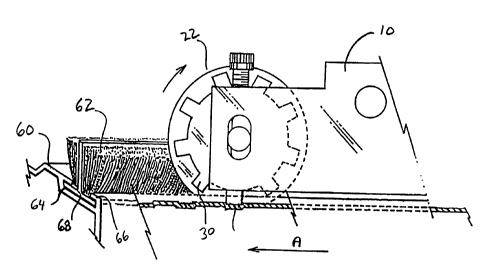
FIGs. 1-6. The preferred tool 10 has a weatherstrip input end 12 and an
output end 14. Input end 12 has a channel 16 bored through the tool body
and extending therethrough to the second end 14. Two legs 18, 20 extend
past the output end 14 and are spaced apart a desired distance. A rotatable
wheel 22 is positioned between legs 18, 20. The wheel 22 has an inserting
CA 02210788 1997-07-17
edge 24 located about its outer first circumference. As shown in FIG. 1,
wheel 22 also has a star-like area 28 with a plurality of projections 30.
The outermost edges of the projections 30 form a second circumference of
the "star." The second circumference of the wheel 22 comprising
projections 30 is referred to as staking wheel edge, or staking edge 26.
The top of tool 10 has adjustable set screws 32, 34. Additional set screws
36, 38 are positioned within the underside of the tool body 10, as shown in
FIG. 5. Adjustment of the four set screws affects the vertical placement of
wheel 22 between legs 18, 20, and affects the distance the wheel
circumference may extend below the bottom of the legs. The vertical
positioning of wheel 22 and the wheel hub 40 can be viewed through hub
guide 42 in the side of legs 18, 20. Screw holes 44 are machined into the
tool for joining the tool to a machine which can position the tool as
desired. Spacing washer 23 is positioned between wheel 22 and leg 20.
FIG. 5 shows detailed features of a preferred embodiment of the
underside of tool 10 to be positioned adjacent the slotted material 60. The
channel 16 through tool 10 emerges at narrow opening 70 via fastener 71.
Feeder guide 72 is securely positioned relative to opening 70. Tool
positioning guide 73 engages the extruded slotted material 60, preferably
nesting adjacent T-slot 64, and positions the tool 10 in a desired
orientation relative to the slotted material 60. In operation, the feeder
guide 72 orients the emerging weatherstrip 62 in a predetermined
orientation proximate the slotted material and the wheel 22 to assist in
proper weatherstrip insertion into the slot 64.
FIG. 6 shows the input end 12 of the tool 10 with channel opening
16.
FIGS. 7-9 show perspective views of tool 10_ adjacent a slotted
material 60 that is to receive a segment of pile weatherstrip 62 into its T
slot 64. FIG. 7 shows the pile strip 62 in position, inserted and staked into
slot 64 of slotted material 60. Tool 10 receives a length of, preferably
continuous pile weatherstrip 62. The weatherstrip 62 has a base 68 and
enters the tool 10 at first input end 12 at channel 16, .and emerges from the
second output end 14 of tool 10 directly over slot 64 of slotted material 60.
As slotted material 60 is passed under the stationary tool 10 in the
direction of arrow A relative to the tool, weatherstrip 62 first encounters
-5-
CA 02210788 1997-07-17
inserting edge 24 of wheel 22 which exerts a downward force on the
weatherstrip 62, forcing the base 68 of the strip into T-slot 64. As the
wheel 22 rotates, and if sufficient force is present, projections 30
comprising the staking wheel surface 26 engage the slot edge, or rim 66
and deform or crimp the edge downward against the pile base 68, holding
or pinning the pile weatherstrip 62 in position within the slot 64.
FIG. 7a shows a segment of extruded slotted material 60 which has
been staked by the wheel of the present invention. Stake marks 61 are
more easily seen in this view where the pile strip has been removed for
illustrative purposes only.
FIGS. la, 3a, Sa and 6a show an alternate embodiment of the
present invention. In this embodiment, the wheel 22 is primarily
responsible only for the inserting function. Reciprocating staking element
21 which extends vertically from the tool body intermittently stakes the
rim of the weatherstrip. It is understood that the reciprocating staking
element is attached to gear mechanisms machined within the tool body. In
operation, it is contemplated that the rotational motion of the insertion
wheel will provide, through a series of interconnecting gears, sufficient
torque and force to drive the reciprocating staking element into the slotted
material rim to adequately stake the pile weatherstripping as desired.
FIG. 8 shows a view of the output end 14 of tool 10. The wheel 22
exerts a force on weatherstrip 62 into slot 64 of slotted material 60.
Inserting edge 24 and staking edge 26 of wheel 22 are clearly visible.
Feeder guide 72 (not shown) presents the strip to the rotatable wheel at a
selected angle and assists wheel 22 in orienting weatherstrip into T-slot 64.
Slot rim 66 is shown crimped, or staked against pile strip base 68, securing
the strip 62 into position within T-slot 64.
FIG. 10 shows an alternate embodiment of the present invention.
Wheel 50 has staking wheel projections S 1 comprising projection edges
53 and an insertion edge 52. In this embodiment, the outermost edges of
the star-like projections occur at the outermost radius and comprise the
staking edge. In operation, this wheel is positioned between legs 18,.20 of
tool 10.
FIG l0a shows a radial view of the wheel of FIG. 10. The staking
projection 51 comprising projection edges 53 clearly extends beyond
-6-
CA 02210788 1997-07-17
insertion edge 52. The projection staking edges as shown are blunt, or are
presented at an angle of about 180° across the width of the edge.
FIG. lOb shows a preferred embodiment of the present invention
wherein the wheel 50 viewed radially shows the staking projection edge
53, of the projection 51 being angled in the axial direction. The preferred
degree of angle is from about 10° to about 80°, preferably from
about 20°
to about 70°, and is most preferably about 30°.
FIG. lOc shows another embodiment of the present invention. In
this radial view of wheel 50, the staking projection edge 53 of the
projection 51 angled at about 120°. It is therefore contemplated that
the
edge of the staking edge projections of the staking wheel can be angled at
any degree in either the axial or radial (not shown) direction of from
1° to
about 180°, depending only upon the desired aggressiveness of staking
to
be accomplished, and taking into consideration the extruded material being
staked: For vinyl extrusions, it has been experimentally determined that
staking is achieved at angles of from about 0 to about 180° preferably
from
about 10 to about 80° and from about 100 to about 170°, with
angles of
about 30° and about 120° being particularly preferred.
FIG. lOd shows a further alternate embodiment of the present
invention. Wheel SO comprises an inserting edge 52 and a staking edge 51
having an angled outer edge 53. In this embodiment, the staking edge is a
continuous edge in contrast to the intermittent staking edge formed by the
plurality of intermittently spaced projections shown in FIGs. 10-lOc and
11-l la. In this embodiment, the inserting and staking surfaces are both
wheels which may be machined out of one piece, or are separate and
affixed together, or are separate but placed proximate to one another, etc.
FIG. i l shows another preferred embodiment of the present
invention with the wheel 80 viewed axially. FIG. l la shows a radial view
of the wheel of FIG. 11. Here, the staking edge formed by the outer edge
of projections 82 is coincident with the inserting edge 81. In other words,
the outermost circumferences of the projection edges of the staking wheel
and the insertion edge of the inserting wheel are about equal.
FIG. 12 shows a machine 90 for inserting and staking weatherstrip
into a slotted extruded material. Weatherstrip 62 is fed from a continuous
roll 91 to first input end 12 of tool 10. Slotted material 60 is supplied from
_7_
CA 02210788 1997-07-17
extruder 92 and pulled from the extruder past staking/inserting station 99
via hugger roll assembly 94 which frictionally engages the extruded
material 60 and provides a specific and regulated pulling force on the
extruded slotted material 60.
In operation, the extruded slotted material is directed to a hugger
roll assembly which grips the material and, through frictional force, draws
the material from the extruder at a specified rate past the stationary
staking/inserting station 99. The tool 10 is held stationary by the
downward force applied to tool 10 by tension screws 95 through clamp 96
supported by stand 97. The downward force is applied to the tool such
that the wheel of the tool exerts a predetermined amount of pressure on the
slotted extruded material. The pressure can be varied by adjusting the
tension screws 95 of clamp 96 upward or downward. The wheel 50 of tool
10 engages weatherstrip 62 as it passes through channel 16 of tool 10, the
tool applying force to the strip 62 sufficient to insert the strip into the
slot
64 of slotted extruded material 60, while simultaneously staking the strip
62 in the slot 64 by deforming the slot rim 66 against the strip 62 and its
base 68 to form stake marks 61.
FIG. 12a is a schematic representation of an alternate embodiment
of the present invention, showing a machine similar to that already
described and shown in FIG. 12, except that reciprocating staking element
101 attached to drive gears within housing 100 is responsible for the
staking function. The wheel of tool 10 remains responsible for inserting
the pile weatherstrip into the T-slot of the slotted extruded material. As
the extruded material advances to the hugger roll assembly, in this
embodiment, the staking element reciprocates intermittently; alternately
rising from and descending into the rim of the slotted material. The
staking frequency may be set as desired, as would be readily understood
by one skilled in the field of reciprocating machine technology. In this
way, the pile strip is inserted and staked simultaneously at one station
along the extrusion line. Such an embodiment may be particularly useful
for extrusion materials that are especially difficult to stake.
It is understood that the combination inserting/staking wheel of the
present invention may be adjustably raised or lowered between the legs of
the tool of the present invention, as desired, via adjusting the set screws
_g_
CA 02210788 1997-07-17
provided. In operation, the tool engages the slotted material by resting
immediately adjacent the slotted material such that the distance of the
wheel extending past the bottom of the legs is sufficient to push, or insert
the pile weatherstrip into the T-slot. The wheels used with the tool may be
adjustably raised, if desired, so that only the inserting edge of the wheel
will impact the weatherstrip, and insert the weatherstrip into the slot.
However, by setting the wheel lower, so that a greater amount of wheel is
visible beneath the legs, and/or increasing pressure on the tool against the
slotted material, the staking~edge of the wheel will impact the edge or rim
of the T-groove immediately after the pile has been inserted into the T-
slot. See FIG. 7. In this way, the strip will be simultaneously inserted by
the inserting edge of the wheel, and staked by the staking edge of the
wheel ino the T-slot.
The lateral position of the wheel is also adjustable by use of one or
1 S more spacing washers 23 on one or both sides of the wheel 22. This lateral
adjustability is a unique feature and especially useful, making the
insertion/staking wheel assembly adaptable for use with T-slotted
materials having varying wall thicknesses, thus requiring varied
positioning of the inserting/staking wheel.
If it is desired to lightly stake the strip (non-permanently) into the
slot, the wheel can be so adjusted. If a firm, permanent staking is desired,
the wheel may be adjusted to descend lower such that a greater amount of
the staking wheel edge will impact and crimp the rim or lip of the T-slot
against the pile weatherstrip, thus firmly staking the strip into the slot.
Such non-permanent staking is often desirable to afford a manufacturer the
opportunity to recycle extruded material. Before recycling can occur, pile
stripping must be removed from the extrusion.
In an alternate embodiment of the present invention shown in FTGs.
10-lOc, a tool may use a wheel SO that has a plurality of projections 51
intermittently oriented about the circumference such that the combined
surface of the projections form the staking edge. In this embodiment, the
staking edge 53 of the wheel 50 would impact the strip and T-slot first; the
pile strip simultaneously being inserted and staked with the same wheel
surface. The inserting wheel may still impact the pile strip and assist in
the strip's proper seating in the T-slot. This wheel would be especially
-9-
CA 02210788 1997-07-17
useful when permanent strip staking is desired, but could also be adjusted
when only inserting, or inserting and lightly staking the strip is desired.
Therefore, it is understood that combination wheels may be
constructed where the staking edge circumference extends past the
inserting edge circumference, the inserting edge circumference extends
past the staking edge circumference, or the staking and inserting edges are
coincident, depending only upon the desired end result. One or both of the
inserting and staking edges may be angled if desired. One or both of the
wheels may have continuous outer circumferences, or may have
intermittent projections. Further, the wheel of the present invention has
been described as one wheel having multiple edges or surfaces machined
into the wheel. It is to be understood that separate, multiple wheels may
be held in close association or affixed together. In this way the inserting
and staking edges would occur on different but juxtaposed wheels.
Still further, the channel that extends through the tool may also
rotate within the tool to achieve an angular path altering effect on the
strip.
In this way, the strip may be presented to the wheel at a specified angle,
different or the same as the angle it entered the tool at the channel opening.
The present invention further contemplates a tool for
simultaneously inserting and staking a weatherstrip into a slot wherein a
rotatable wheel or other inserting guide or plate contacts the weatherstrip
and inserts the strip into a slot while a staking means simultaneously stakes
the strip into the slot. The staking means may be a reciprocating punch, a
staking plate applying a constant force to the slot rim so as to crimp the
rim, or any other means of crimping the extruded slot material rim so as to
stake the strip in place within the slot in temporary, semi-permanent, or
permanent fashion as desired.
Temporary staking is understood to mean staking the pile strip into
the slot so lightly that the strip may be removed from the slot with minimal
force applied to the strip. Semi-permanent staking requires significant
force to remove the strip from the slot, but the strip and slotted extruded
material may be salvaged or recycled. Permanent staking is understood to
mean that the strip cannot be removed from the slot without destroying
either or both of the extruded material and/or the strip.
-in-
CA 02210788 1997-07-17
The pattern of projections on the staking wheel is not critical. The
staking wheel projections may be of any desired configuration, with blunt,
rounded, pointed or angled, etc. ends. The staking wheel edge and
inserting edge may also be one continuous surface or may be intermittent,
such as by having a plurality of regularly or irregularly spaced projections.
If multiple wheels are desired, it is contemplated that one or both wheels
may be rotatable or fixed in position.
In the most preferred embodiment, the tool is not self driven; i.e.
no motorization within the tool is responsible for rotating the
insertion/staking wheel. However, the combined effect of the pressure
exerted on the stationary tool by the clamp, and the frictional force of the
wheel against the moving extruded slotted material results in the wheel's
rotation. It has been found that the staking and smooth rotational wheel
movement is facilitated when more than one staking wheel projection
contacts the extruded material at all times.
Many other modifications and variations of the present invention
are possible to the skilled practitioner in the field in light of the
teachings
herein. It is therefore understood that, within the scope of the claims, the
present invention can be practiced other than as herein specifically
described.