Note: Descriptions are shown in the official language in which they were submitted.
CA 02210802 1997-07-18
Wo ~6/23647 PCT/US96/01451
' DESCRIPTION
RAPID RECOATING OF THREE-DIMENSIONAL
OBJECTS FORMED ON A CROSS-SECTIONAL BASIS
TECHNICAL FIELD OF THE INVENTION
The current invention relates generally to the field known as rapid
prototyping and m~nnf~eturing ("RP&M"), stereolithography or solid im~ging,
which involves the fabrication of three-rlimen~ional objects on substantially a cross-
section by cross-section basis. More particularly, the current invention relates to
improved methods and app~dlu~ for providing a layer of building material adjacent
to an already-formed object cross-section, in preparation for forming a successive
object cross-section out of the layer of building m~teri~l
BACKGROUND
Solid im~ging generally involves the formation of three-dimensional
objects according to coll~ulel comm~n~1~ based on a co~ uleL aided design
("CAD") or other three-dimensional representation ofthe object. One solid im~ping
technique recently developed is stereolithography which is described in U.S. Patent
Nos. 4,575,330 and 5,184,307, both of which are incorporated by reference as if
fully set forth herein. Appearing below is a summary of the basic steps of a
stereolithographic embodiment:
2 o 1. Generation of a three-dimensional object design in a CAD system and storage of the design data in a CAD file;
2. Compiling data from the CAD file into numerous thin "slices"
each representing a thin cross-sectional layer of the three-~limen~ional object;3. Transfer of the CAD file to a StereoLithographic Apparatus
("SLA");
4. Coating a layer of building m~t~ri~l adjacent to a previously
formed object cross-section in pl~dlion of forming a subsequent object cross-
CA 02210802 1997-07-18
WO 96/23647 PCTIUS96101451
section. The building m~tt?ri~l layer is preferably uniforrnly coated at a~ ro~l;ate
thickness so that the subsequently formed object cross-section meets tolerance
requirements;
5. Selectively exposing the building material layer to synergistic
stimulation to solidify or otherwise physically transform the building material layer
at those locations which collectively represent the object cross-section to be formed;
6. Repeating steps (4) and (5) to altern~tingly form successive
building material layers and object cross-sections until the three-dimensional object
is formed; and
7. Post processing the newly-formed object such as by removing
residual building material clinging to the object, removing the object from a
platform on which it was formed, exposing the object to additional synergistic
stim~ tion to ensure complete solidification of the building m~t~ri~l and removing
supports.
Additional details about stereolithography are available in the
following publications and patents, all of which are hereby incorporated by reference
herein as though set forth in full:
PCT Pub. #WO 92/20505 PCT Pub. #WO 91/06378
PCT Pub. # WO 92/08200 JP Pat. App. # 291647/1990
PCT Pub. #WO 89/10256 U.S. Pat. 5,059,359
PCT Pub. #WO 89/10249 U.S. Pat. 4,996,010
PCT Pub. #WO 89/10254 U.S. Pat. 4,999,143
PCT Pub. #WO 89/10259 U.S. Pat. 5,015,424
PCT Pub. #WO 89/11085 U.S. Pat. 5,058,988
PCT Pub. #WO 89/10801 U.S. Pat. 5,123,734
EPO Pub. # 85/171069 U.S. Pat. 5,059,021
JP Pub. # 62-3596 U.S. Pat. 5,184,307
PCT Pub. #WO 90/03255 U.S. Pat. 5,104,592
PCT Pub. #WO 90/15674 U.S. Pat. 5,143,663
- CA 02210802 1997-07-18
. , ~
W O 96/23647 PCTrUS96/01451
U.S. Pat. 5,182,056
U.S. Pat. 5,130,064
U.S. Pat. 5,174,931
U.S. Pat. 5,096,530
U.S. Pat. 5,141,680
U.S. Pat. 5,192,469
U.S. Pat. 5,321,622
U.S. Pat. 5,182,715
U.S. Pat. 5,234,636
U.S. Pat. 5,238,639
U.S. Pat. 5,256,340
U.S. Pat. 5,182,055
Building materials typically used iIl solid im~ing may exhibit fluid-
like characteristics but solidify or otherwise physically transform in response to
synergistic stimulation. The fluid-like characteristics facilitate dispensing a building
material layer adjacent to a previously formed object cross-section, as well as
smoothing the building m~tçri~l layer surface in plG~dLion of forming the next
object cross-section. Depending on the coating technique used, suitable materials
include transformable liquids such as therm~lly polymeri7~ble resins,
2 0 photopolymeri_able resins, a first part of a two-part epoxy, sinterable powders,
bindable powders or combinations thereof and the like. Liquid materials may alsocontain inert filler m~teri~ls
Various forms of synergistic stim~ tion may be used as long as the
building m~teri~l is responsive to the synergistic stimlll~tion. These include certain
2 5 wavelengths of electromagnetic radiation, such as infrared radiation, visible
radiation and ultraviolet radiation. Other forms of synergistic stimulation which
may be used are particle beams, reactive chemicals dispensed onto the building
-
CA 02210802 1997-07-18
Wo 96/23647 PCT/US96/01451
m~teri~l such as a photoinitiator, the second element of a two-part epoxy, binder
m~teri~ and the like.
The design data representative of the three-tlimen~ional object can be
obtained from various sources including CAD data, CAT scan data, m~nll~lly
programrned data and data derived from techniques for sc~nning physical objects. If
this data is initially in layer form, the compilation process may be reduced to
creating ~plu~liate layer fill data. However, additional compilation may be desired
or required to transform the data into proper forrn to meet accuracy, process or other
requirements such as how supports will be built along with the object. The
1 0 procedures and a~ s described in U.S. Patent Nos. 5,182,055, 5,184,307,
5,192,469, 5,209,878, 5,238,639, 5,256,340, 5,273,691 and 5,321,622, 5,345,391,
and U.S. Patent Application Serial Nos. 08/233,026 and 08/233,027 both filed April
25, 1994, address the generation of a~plopliate layer data and all these patents and
patent applications are incorporated by reference as if fully set forth herein. Also
1 5 incorporated by reference as if fully set forth herein is the publication entitled Rapid
Prototyping & M~tn~f~ tt~ring: F--ncl~tment~l~ of Stereolithography, First Edition,
authored by Paul F. Jacobs, Ph.D., and published by the Society of ManufacturingEngineers, Dearborn, Michigan in 1992.
The current invention is directed prtm~trily to step (4) above, i.e.,
2 0 coating a building m~teri~l layer adjacent to a previously formed object cross-
section in ~ Lion for forming a subsequent object cross-section. Several
approaches have been used in the past to perform this coating step, most often with a
building m~t~ri~l comprising a liquid photopolymeri7~hle resin. However, these
prior approaches have resulted in varying degrees of layer accuracy and
2 5 nonuniformity, and/or have required excessive time to form the coatings, which
problems have the following ramifications.
First, it is important that the building m~t~ri~l layer is ullirollll and of
a~r~llate thickness so that upon solidification, the resulting object cross-section
exhibits rlimen~ional accuracy. Indeed, the accuracy of the sllcces~ive building
CA 02210802 1997-07-18
WO 96/23647 PCT/US96/01451
material layers directly impacts the accuracy of the final object in view of potential
misplacement of object features upon exposure to synergistic stimulation and
potential accnm~ te(l errors which may result frorn errors on sllccessive layers.
Second, it is desirable to minimi~ the time required to form a
building material layer because the cumulative coating time of the successive layers
represents a significant portion of the overall object build time. Indeed,
photopolymer resins exhibit slow flow velocities due to viscosity and surface
tension. If driven only by gravity, imperfections in photopolymer building material
layer surfaces can take prohibitively long time periods to relax or otherwise become
uniform with the rest of the building material layer surface. This in turn increases
object build time, reduces m~rhine throughput, and reduces the cost effectiveness of
solid im~ging
Third, the extent of inaccuracy and nonul~irol,llity of the building
m~t~ri~l layer as well as the amount of time necessary to form it may vary with the
geometry of previously formed cross-sections. Accordingly, automated coating of
building material layers is difficult because there may be no set correction
parameters that might otherwise be used if coating inaccuracies were constant.
A description of several previous approaches is set forth in the
following U.S. Patents and Patent Applications, the disclosures of which are all2 o incorporated by reference as if fully set forth herein:
1) U.S. Patent Application Serial No. 07/414,200 by Hull et al
filed September 28, 1989, and its ~;ullellLly pending co~ ion Serial No.
08/230,443 filed April 20, 1994, are directed to covering the building material layer
surface with a film which is then peeled from the surface. Before or after peeling,
the surface is exposed to synergistic stimulation to form the next object cross-section.
2) U.S. Patent Application Serial No. 07/495,791 by Jacobs et al
filed March 9, 1990, and its ~;ull~nlly pending continn~tion Serial No. 08/198,655
filed February 18, 1994, are directed to the use of vibrational energy applied directly
CA 02210802 1997-07-18
WO 96/23647 PCr/US96/OlqSl
to the building m~tt?ri~l layer surface or to a previously formed object cross-section
to decrease the time required for surface imperfections to vanish or level out to a
tolerable level.
3) U.S. Patent No. 5,174,931 issued to Almquist et al. and its
currently pending continll~tion Serial No. 08/146,562 filed November 2, 1993 aredirected to, among other things, using a member such as a doctor blade, to smooth or
spread a coating of building material over a previously formed cross-section of the
object.
4) U.S. Patent No. 5,096,530 issued to Cohen et al. is directed to
1 0 forming a building material layer which is supported by a frame and the force of
surface tension. The layer is then laid above a previously formed object cross-
section.
5) U.S. Patent No. 5,071,337 issued to Heller et al. and its
~;ullclllly pending col";~ tion-in-part Serial No. 08/299,879 filed September 1,1994, are directed to, among other things, using a dispensing device such as an
applicator bar to form uniform building material layers.
The doctor blade approach listed above typically involves sweeping a
bar or other device across the surface of a building material layer thereby smoothing
it. Though this may reduce coating time, other problems remain such as those
2 o associated with leading edge bulge, trapped volumes, scoop-out and other problems
described in previously incol~o,d~cd U.S. Patent No. 5,174,931.
Other coating approaches have been suggested beyond those listed
above. An electrically charged or uncharged counter-rotating roller which spreads a
mound of powder into Ulli~llll layers is disclosed in PCT Patent Application No.PCT/US87/02635, Publication No. WO 88/022677 by Deckard, and in U.S. Patent
No. 4,938,816 issued to Beaman et al. However, the roller disclosed therein is 7
generally not suited for use with liquid building m~teri~lc because liquids may cling
to the roller unlike the powders described in the above references which are instead
ejected in front of the roller. This clin~in~ action may also cause building material
CA 02210802 1997-07-18
WO 96/23647 PCr/US96/01451
to be carried over the roller and redeposited behind it thereby creating a nonuniform
building layer. Furthermore, liquid mounds also tend to sink or spread out into
previously dispensed volumes of unsolidified liquid. In any event, the Deckard and
Beaman references do not address how such a roller might be used with liquid
building m~teri~l~
Several basic aspects of using a dispensing slit or curtain coater in a
stereolithographic process are disclosed in J~p~n~se Patent Application 59-237054,
laid open to the public as Japanese Publication 61-114817(A) on June 2, 1986, filed
by Morihara et al. The slit coater remains stationary as the container of liquid1 o building material is moved back and forth beneath it. The slit coater dispenses
building m~teri~l having a thickness equal to that ofthe desired solidified object
cross-section. However, Morihara's slit coater is not suitable for producing high-
resolution objects for at least the following reasons.
First, forming building material layers having a thickness equal to
.5 that of the desired object cross-section does not account for the ~hrink~ge which
typically occurs as the building material solidifies. This in turn leads to inaccuracies
in the vertical ~limen~ions of the object, formation of non-planar object cross-sections especially in transitional regions between supported and unsupported
portions of a cross-section, and uncontrolled positioning of the working surface.
2 o Second, Morihara's slit coater does not account for the volumetric
difference of m~teri~l dispensed when the container moves at constant velocity
versus when it accelerates and decelerates near the ends of its line of travel. This
results in a nonuniform thickness across the building material layer.
Third, Morihara's slit coater cannot dispense material at locations of
2 5 the c~ nt~iner which are inaccessible to the slit coater. This either reduces the
accuracy of the overall coating formed or the usable working area of the container.
Fourth, Morihara's slit coater does not recognize that in certain
stereolithographic embotlimentc, one must coat a building m~tPri~l layer over the
entire surface of the liquid bounded by the container before the building material
CA 02210802 1997-07-18
W O 96123647 PCTAUS96101451
layer achieves the desired thickness. This is because when building m~tt?ri~l isdispensed in regions that are not closely supported by solidified m~t~ri~l, the
building material will not simply remain at the surface of the liquid in the container.
Tn.~te~(l, it serves to raise the liquid level in the entire container thereby decreasing
the thickness of the building material layer at the point it was just dispensed at.
Only after material has been dispensed over all such unsupported regions will the
building material surface level reach the desired level. In certain circumstances
however, such as when coating very thin building material layers on the order of0.004 inches or less, one may ignore this problem.
Fifth, the building m~teri~l in Morihara's container is likely to shift
due to the repeated to and fro container motion. Such shifting would likely result in
nonuniform coating thickne~ses and/or increased layer formation times. In fact,
even if the container is moved to and fro at moderate speeds, the material in the
container may slosh out of the cont~iner. For all the foregoing, it appears thatMorihara does not disclose an apparatus or method to rapidly and accurately recoat
building m~t~ri~l layers.
Beyond the problems of the particular approaches discussed above,
other problems involve the dispensing of a known quantity of building material, or
avoiding the accumulation of small errors into large cumulative er.rors as successive
2 o layers are coated. Accordingly, there is a need in the RP&M art for methods and
a~dlus which overcome the problems discussed in this background section as
well as other problems. Other objects, useable alone or in combination, will be
a~ale~lL to one of skill in the art from the te~ ingc found herein.
DISCLOSURE OF T~E INVENTION
2 5 The current invention regards improved apparatus and methods for
forming s~lcces~ive building m~teri~l layers in ~dlion of forming successive
cross-sections of an object built on substantially a cross-sectional basis.
CA 02210802 1997-07-18
WO 96123647 PCI~/US96/014!;1
r In a first embodiment, a counter rotating roller is swept across an
initial building material layer to form a building m~terial layer of desired thickness
and uniformity. Several variations of this embodiment are disclosed.
In a second embodiment, an ink jet print head dispenses building
material from a plurality of ink jets to form a building material layer. Severalvariations of this embodiment are disclosed.
In a third embodiment, an applicator includes a plurality of spinning
wheels on which building material is delivered and then ejected from the applicator
to form a building material layer. Several variations of this embodiment are
1 0 disclosed.
In a fourth embodiment, an applicator is used to apply a building
material layer from above the object being formed. Several variations of the
applicator are disclosed.
In a fifth embodiment, an applicator dispenses a plurality of building
m~t~ri~l streams from above the object, which streams merge upon cont~cting the
object or other surface to form a building material layer. Several variations of this
embodiment are disclosed.
In the foregoing embo-liment~, variations on how building material is
supplied to the applicator or other device used to dispense building material are
2 o disclosed. Also disclosed are methods and a~dlus to monitor the overallrlimçn~ions of the object as it is being built to avoid and/or correct accllm~ tç~l
errors. Also disclosed are methods and app~dlus to ~letennin~ the extent to which a
building m~tçri~l layer should be formed when taking trapped volumes into account.
Each of the above embo~liment~ may be used independently of the other
2 5 embodiments to achieve an improvement in coating accuracy or in coating formation
time or both. Alternatively, combinations of the above embotliment~ or
combinations of dirrelc.ll elements of the above embo~liment~ may be used for
favorable recoating results.
CA 02210802 1997-07-18
WO 96/23647 PCT/US96/01451
BRIEF DESCRIPTION OF THE DRAWINGS
Figure 1 is a cross-section of a stereolithographic a~paldlLIs forming a
building m~tt~ l layer.
Figures 2a-2d show an ~pa alus and method for forming a building
material layer using a counter rotating roller.
Figure 2e shows the interaction between a counter rotating roller and
building material layer.
Figures 3a-3b show an ~p~ildLLls and method for forming a building
m~teri~l layer using a counter rotating roller with a dam.
Figure 4a shows an apparatus and method for forming a building
m~t~ l layer using a counter rotating roller, dam and a screw.
Figure 4b is a top view of the screw of figure 4a.
Figure 4c shows an a~dLus and method for forming a building
material layer using a counter rotating roller, dam and a trough.
Figure 4d is a top view of the trough of figure 4c.
Figures Sa-5b show an a~~~lldLUS and method for forming a building
m~teri~l layer using a counter rotating roller, dam and a dispenser.
Figure 5c is a side sectional view of the dispenser of figures 5a-5b.
Figure 5d shows an orifice network of the dispenser of figures 5a-~c.
2 o Figures 6a-6b show an ~)paldLUS and method for forming a building
material layer using a counter rotating roller, dispenser, dam, and a screw.
Figure 7a shows an ink jet print head dispensing building material.
Figures 7b-7d show ~lt~ te ink jet array configurations.
Figure 7e shows a building m~teri~l layer and a working surface v
2 5 formed after dispensing.
Figure 7f shows an ink jet print head dispensing building m~tPri~l
Figure 7g is a top surface of a previously formed object cross-section.
Figure 8a shows an applicator including a roller dispensing building
m~t~n~l
CA 02210802 1997-07-18
WO 96/23647 PCT/US96/01451
. Figure 8b shows a roller.
Figure 8c shows an alternate roller including a plurality of wheels.
Figure 8d shows a wheel comprising a porous material.
Figure 8e shows a wheel including holes.
Figure 8f is a sectional view of an applicator including an array of
spinning wheels dispensing building material.
Figure 8g shows a wheel having high points.
Figure 8h shows the tangential direction of material ejection from a
wheel.
Figure 8i shows a plurality of wheels in an envelope.
Figure 8j shows an applicator including an array of spinning wheels
and impeller dispensing building material.
Figure 8k shows an applicator inchlding a piston sprayer dispensing
building material.
Figures 81-8m show a rotating applicator including a spinning wheel
array dispensing building material.
Figure 8n shows an applicator dispensing m~t~
Figure 9a shows an appa dlus and method for forming a building
material layer using an applicator.
2 0 Figure 9b shows an applicator dispensing m~tçri~l
Figure 9c is a perspective view of an applicator.
Figure 9d is an end view of an app]icator.
Figure 9e is a side view of an applicator.
Figure 9f is a bottom view of an applicator.
2 5 Figure 9g shows an applicator gap.
Figure 9h shows an applicator clearance.
Figure 9i shows an applicator absorbing m~tçri~l
Figure 9j shows an applicator dispensing m~tçri~l
Figure 9k is an end view of an applicator.
.
CA 02210802 1997-07-18
Wo 96/23647 PCr/US96/01451
Figure 91 is a perspective view of an applicator.
Figure 9m is an end view of an applicator.
Figure 9n is an end view of an applicator.
Figure 9o shows an applicator with a roller absorbing m~t~ri~l
Figure 9p shows an applicator including a vacuum arrangement
dispensing m~t~ri~l
Figures 9q-9q are end views of applicators.
Figure 1 Oa shows an applicator including an array of spray nozles
~repa,illg to dispense building material.
0 Figures 10b-10c shows alternate spray nozzle array configurations.
Figure 1 Od shows the applicator of figure 1 Oa dispensing material.
Figure 1 Oe shows streams of material from an applicator merging
before re~ching the intended surface.
Figure 1 0f shows the eccentric motion of an applicator including a
spray nozzle array.
Figure 10g shows streams of m~t~ri~l before re~ching the intended
surface.
Figure 1 Oh shows lines of m~teri~l after having reached the intended
surface.
2 o BEST MODE FOR CARRYING OUT THE INVENTION
Figure 1 generally depicts a stereolithographic apparatus ("SLA") 10
in which object 12 is formed, and is set forth to f~mili~ri71? the reader with terms
used herein. SLA 10 may include a vat 14 which contains a volume of the buildingmaterial 16 used to form object 12. Object 12 may be built on platform 18 which
2 5 may be vertically movable and coupled to support arms 17 that may be coupled to a
co~ .ulel-controlled elevator (not shown). Object 12 is formed of ~llcces~ive cross-
sections which are shown by the dashed lines. The last-formed object cross-section
20 has a top surface 22 on which the next layer of building m~tPri~l 24 is formed.
CA 02210802 1997-07-18
wo 96/23647 PCr/Uss6/01451
In pl~d~ion of forming the next object cross-section, building
m~teri~l layer 24 may be formed in several ways. Platform 18 may be lowered
while m~ t~ ; the surface of the volume of material 16, i.e., working surface 26,
at a fixed level. The term working surface 26 typically refers to the surface of the
volume of building material 16 in vat 14. Preferably, working surface 26 is at adesired level or plane, and is thus a "desired working surface" that is located at a
specified distance from the source 28 of synergistic stimulation during exposure to
synergistic stim~ tion. Throughout the disclosure below, the actual working
surface and desired working surface are both denoted with reference numeral 26 but
where the actual and desired working surfaces may deviate from each other, the
disclosure explains such deviation.
Alternatively, platform 18 and thus top surface 22 may remain
stationary at a fixed level, and the volume of material 16 in vat 14 may be increased
thereby raising working surface 26. This may occur by ~ lphlg more material intovat 14 from below working surface 26, or by dispensing more material into vat 14from above working surface 26. A combination of the foregoing approaches is alsopossible.
Alternatively, building m~teri~l layer 24 of figure 1 may be formed
by "deep-dipping" platform 18. That is, platform 18 and thus surface 22 may be
2 0 lowered more than the int~nt1ecl thickness of the next object cross-section below
working surface 26 so that m~teri~l 16 flows over surface 22 more easily. Platform
18 is then raised so that the thickness of layer 24 approximates the desired thickness.
~ltern~tively, working surface 26 may be raised in excess and then lowered. Deep-
dipping is used because if platform 18 is lowered or working surface 26 raised an
2 5 amount equal to only one layer thickness, m~teri~l 16 may not flow, or at least not
flow in a reasonable time period, over surface 22 due to viscosity and surface tension
effects. Tn~te~(l, material 16 will typically form a boundary around the periphery of
surface 22 (see boundary 68 in figure 5a). As explained later, the configuration of
object cross-sections below the last-formed cross-section 20 may affect where
CA 02210802 1997-07-18
Wo g6/23647 PCr/US96/01451
boundary 68 is formed. This boundary may remain stationary or ~ltern~tively may
move slowly inward toward the center of the previous cross-section. Deep-dippingis discussed in detail in previously incorporated U.S. Patent No. 4,575,330 and
5,174,931. Working surface 26 may be raised relative to top surface 22 by other
techniques which also help serve to form a building material layer 24.
The thickness of the building material layer 24 may substantially
approximate the desired thickness of the next object cross-section or may vary from
the desired thickness. One reason that the thickness of layer 24 may be varied from
the thickness of the next object cross-section is to compensate for errors that may
have arisen in connection with forming previous object cross-sections, or to
compensate for anticipated errors.
For example, since liquids such as photopolymerizable resins
typically shrink as they solidify, building m~tçri~l layer 24 may be formed thicker
than the intentle~ object cross-section to compensate for the thickness that will be
lost to ~hrink~ge. Also, to ensure that the actual working surface 26 remains a
proper distance from the source of synergistic stimul~tion 28 so that is therefore a
desired working surface 26, and to rectify thickness errors that may have
accum~ te~1 over successive layers, independent liquid leveling may occur in
association with the recoating process for each layer or for periodic layers.
2 o Depending on the timing, amount and direction of level correction, a building
m~teri~l layer thickness may be somewhat greater or less than the desired thickness
of the next object cross-section. Lastly, due to possible inaccuracies in the building
m~teri~l layer used to form the last formed object cross-section 20, or due to
possible distortions in the last object cross-section 20 arising from ~hrink~ge or curl,
2 5 the current building m~tçri~l layer thickness may vary from the desired thickness.
Another reason why the thickness of layer 24 may be varied from the
thickness of the next object cross-section, at least initially, is because building
m~tçri~l layer 24 may be formed in several steps, i.e., it is initially formed at a
certain thickness and then adjusted to a desired thickness. For example, when deep-
CA 02210802 1997-07-18
WO 96/23647 PCIIUS961014Sl
,~ dipping occurs, building m~teri~l layer 24 may initially be thicker than desired
because excess m~t~.ri~l 16 may remain over surface 22 after platform 18 is brought
back up. This thicker-than-intended initial building material layer 24 may then be
adjusted to the desired thickness by a doctor blade or other device as describedbelow. Where a doctor blade or other smoothing device is used to form a buildingmaterial layer 24, the thickness of layer 24 may end up being less than desired
because the doctor blade may have swept away too much material 16. Alternatively,
the thickness may be greater than desired because the doctor blade may not have
swept away sufficient m~teri~l This results in the actual working surface not
coinciding with the desired working surface.
In some circ-lm.~t~nces the initial building material layer 24 may be
adjusted to the desired thickness by raising or lowering working surface 26 relative
to top surface 22 an additional increment to compensate. In any event, it is generally
advantageous to ~ietr.rmine the coating error on a first layer and to compensate for
that error by adjusting the coating thickness of a subsequent layer of building
material.
After a building m~teri~l layer 24 of desired thickness is formed, it is
exposed to synergistic stim~ tion from a source of synergistic ~timlll~tion 28. This
causes building material layer 24 to solidify or otherwise physically transform
thereby forming the next object cross-section. Successive building material layers
24 and object cross-sections 20 are then alten ~tingly formed to complete the object
12.
COUNTER-ROTATING lROLLER
Reference is now made to figures 2a-2d, which show a first
2 5 embodiment of the current invention in various stages of forming a building material
layer 24. Elements common to figure 1 are similarly numbered. In this
embodiment, a building material layer 24 is initially formed by raising working
surface 26 relative to the top surface 22 as ~ cllssecl above, and then a counter
CA 02210802 1997-07-18
Wo 96/23647 PCI/US96/01451
16 ~,
rotating roller 30 is swept across building m~teri~l layer 24 thereby ren-lering it t
substantially uniform and of desired thickness. This embodiment may be used witha liquid building material such as a photopolymerizable resin, a plcre~cd resin being
SL 5170 m~nllf~tured by Ciba-Geigy, Ltd. and sold by 3D Systems, Inc. of
Valencia, California. A p~er~cd source of synergistic stim~ tion 28 is 325 nm
radiation produced by a HeCd laser.
As discussed in more detail below, a counter rotating roller is one
which translates across working surface 26 and which rotates counter to the direction
of translation such that the net sum of (a) its rotational (tangential) velocity at a point
near the working surface of the material, i.e., the angular velocity of roller 30 as
measured in radians/unit time multiplied by the radius of the roller 30, and (b) its
translational velocity, i.e., the velocity at which the center of the rotating roller 30
tr~n~l~tes, is greater than either the rotational or tr~n~l~tional velocities taken alone.
In other words, the direction of rotation is opposite, i.e. counter, to the direction in
which the roller would rotate if it were rolling along the plane ofthe working
surface.
Figure 2a depicts the stage of the building process where the last-
formed object cross-section 20 has been formed by exposure to synergistic
stimulation from a source 28. At this stage, top surface 22 of the last object cross-
2 o section 20 may be substantially co-planar with working surface 26 or slightly
depressed due to ~hrink~ge of m~teri~l 16 upon its solidifying. As shown, objectcross-section 20 includes void 29 which corresponds to a location where object 12 is
not solid per the object's design or the design of the particular stereolithographic
building style being used to form the object. Other voids 29 are also shown in
previous object cross-sections.
At this stage, roller 30 is preferably located or parked near the
periphery of vat 14 or at least beyond the area of surface 26 that was exposed to
synergistic stim~ tion. In this manner, roller 30 and associated haLdwalc were not
located over object 12 and thus avoided interfering with the synergistic stimulation
CA 02210802 1997-07-18
Wo 96/23647 PCTIUS96/01451
17
being directed towards object 12. The parking position of roller 30 during the
exposure step depends on a number of factors. These factors include 1) whether or
not roller 30 stops rotating during exposure, 2) whether or not successive sweeps of
roller 30 across vat 14 are performed in opposite sweeping directions and therefore
with successive reversals in rotational velocity, 3) the extents of the region to be
exposed when exposing building material layer 24, 4) the extents of the last-formed
object cross-section 20 just exposed and 5) the extents of the regions exposed in
association with a number of prece.ling layers, e.g. layers corresponding to the last
previously formed 1/25 to 1/4 inch of object cross-sections. Preferably, reverseroller 30 sweeps a minimlmn distance per layer so as to minimi7e the time associated
with recoating. In any event, building material layer 24 may now be formed in
~pald~ion for forming the next object cross-section.
Figure 2b shows building material layer 24a which has been initially
formed by raising working surface 26 relative to top surface 22. This may be
accomplished by lowering object 12 into vat 14 or by raising surface 26 while object
12 remains stationary. A doctor blade or other smoothing device may also have
operated on surface 26. As tli~cll~erl above, the initial thickness of layer 24a may
vary from the desired thickness of the next object cross-section. In fact, the initial
thickness of layer 24a is typically significantly greater than the desired thickness of
2 0 the next object cross-section. However, the initial thickness of layer 24a may not be
ullirollll wherein some regions are thinner than desired while other regions arethicker than desired.
After building material layer 24a is initially formed, hllp~lrections in
the working surface 26 may remain such as bulges 40, depressions 42 and holes 442 5 which if not reduced or elimin~te~l could create inaccuracies in the next object
cross-section. If severe enough or if built-up from a number of layers, these
illl~t;lrections could result in ~lel~min~tion between object cross-sections or a
collision between the last-formed cross-section 20 and any coating device which is
swept above the desired working surface 26. The size and origin of surface
CA 02210802 1997-07-18
WO 96/23647 PCT/US96101451
deformations depend largely on how building m~teri~l layer 24a was initially
formed. If deep dipping was used, bulges 40 and overall excess thickness over
surface 22 would probably result. If layer 24a was initially formed by bulk
dispensing from a sweeping hopper traversing above working surface 26, any
variance in the dispensing rate could cause bulges 40 or depressions 42. If a doctor
blade or other smoothing device was used in initially forming layer 24a, bulges 40
may be formed which result from leading edge bulge or underflow of material in
trapped volumes, or depressions 42 and holes 44 may be formed which result from
scoopout of material from shallow regions.
o In any event, after layer 24a is initially formed, a counter-rotating
roller 30 may then be used to form a building material layer 24 which is uniform and
of desired thickness in plep~Lion for forming the next or subsequent object cross-
section. Alternatively, a reverse roller, i.e., counter-rotating roller, may be swept
over the previously formed cross-section without first forming an initial layer 24a.
Figure 2c depicts the reverse roller 30 after having partially traversed the previously
formed object cross-section 20 from left to right. Figure 2d depicts the reverse roller
30 after having completed its traverse. A partially formed desired layer of building
m~teri~l 24b is shown to the left of the roller 30 in figure 2c while a completed
desired layer of building material 24b is shown over the entire previously formed
2 0 cross-section 20 in figure 2d.
Roller 30 is preferably cylindrical and its axial length may cover a
substantial portion of the transverse flimen~ion of vat 14 (~1imen.~ion typically
perpendicular to the sweeping direction of roller 30). This allows a significantportion of vat 14, and more importantly the entire portion of vat 14 which is within
the transverse ~limen~ion ofthe next object cross-section, to be swept by a single
pass of roller 30. ~ltern~tively, multiple rollers 30 of shorter axial length may be
used. This multiple roller configuration may be advantageous for building smaller
objects because only one of the shorter rollers may actually be needed to act upon
CA 02210802 1997-07-18
Wo 96/23647 Pcrluss6lol45
19
that portion of working surface 26 within the dimensions of the next object cross-section.
In a further ~ltern~tive, roller 30 may be swept in a direction which is
not perpendicular to the axis of roller 30. Here, the axis of roller 30 is oriented less
than 90~ from the sweeping direction but greater than 0~, the ~lcfellcd axis of
orientation being between 45 ~ and 60 ~ . If doctor blades such as those disclosed in
the parent application, U.S. Patent Application Serial No. 08/146,562, are used,either alone or in combination with a reverse roller when forming a layer of material,
they may be similarly oriented to enhance recoating.
There is generally no need to smooth the entire working surface 26 of
vat 14 with roller 30 because inaccuracies in those portions of surface 26 not
exposed to synergistic stimulation generally do nol: occur. This is because large flow
paths exist that allow rapid leveling out of any variation in the height of surface 26.
Furthermore, it is plcrcllcd to actively smooth only those portions of surface 26 that
contribute to object accuracy because to smooth the entire surface 26 increases
recoating time, and in turn, overall object build time. Generally, three criteria
determine the extent to which surface 26 should be smoothed by roller 30.
First, after sweeping roller 30 to form a ullirol~ll building material
layer 24, roller 30 and its associated hardware should ultim~tely be located beyond
the region of working surface 26 to be exposed to synergistic stim~ tion when
2 o forming the subsequent object cross-section from the layer 24 just formed. Second,
enough of surface 26 should be smoothed to forrn a uniform layer 24 over the
regions previously exposed when forming the last-:formed object cross-section 20.
Thus according to these first two criteria, roller 30 should be swept to a location
beyond what was exposed in forming the previous cross-section and beyond what is2 5 to be exposed in forming the subsequent cross-section. In many instances if these
two criteria are met, object formation may typically proceed. However if fail-safe
reco~tin~ is desired, a third criteria should be considered which, as discussed below,
involves considering the regions exposed in association with one or more cross-
sections forrned prior to the last-formed cross-section 20.
CA 02210802 1997-07-18
WO 96/23647 PCr/US96/014S
When working with a vat 14 co~ g liquid photopolymer, it has
been found that all portions of regions which are deep and connected by large flow
paths readily attain the same surface level. This is illustrated in figure 2d where
surface areas A, and A2 are located over deep regions Rl and R2, and where regions
R, and R2 are generally contiguous to each other such that the flow path
therebetween is generally unobstructed. Here, if building material is added to
surface area A~, m~teri~l 16 in vat 14 will generally flow between regions R~ and R,
such that surface area A2 quickly attains the same level as surface area A,.
However, it has been found that when material is added to surface
areas over shallow regions such as void 29 and up-facing regions 31, 33, exorbitant
amounts of time may be required for this surface area to attain the same level as that
over deep regions. Thus any excess material thickness in shallow regions can take
unacceptable amounts of time to reduce or rise to the desired level when acted upon
by only the forces of gravity and surface tension. Likewise, any shallow regionswith a coating thickness shortage may require an exorbitant amount of time to
increase to the desired level.
The depth at which a shallow region becomes potentially koublesome
depends on the viscosity and surface tension of the building material and on thesurface energy of the building material which has already physically transformed.
2 o Shallow regions having a depth below the desired working surface 26 of between
less than 40 mils (1 mm) to about 240 mils (6 mm) may exhibit the problem
clle~ecl above and may be considered troublesome. If an extremely viscous
building m~t~ri~l is used, e.g., viscosity excee~lin~ 10,000 centipoise, depths
considered troublesome may extend even deeper.
2 5 In any event, the third criteria is ensuring that roller 30 sweeps
beyond all of these shallow regions. These shallow regions can be accounted for by
storing the m~imllm cross-sectional ~limen~ions for all previously formed objectcross-sections which exist within the defined shallow troublesome depth, and
~n~llrin~ that roller 30 not only sweeps to a location which fulfills criteria 1 and 2,
CA 02210802 1997-07-18
Wo 96/23647 Pcr/uss6/01451
21
but also to a location which is beyond the boundaries of all cross-sections within the
troublesome depth range.
For example, if a troublesome depth range is defined to include
shallow regions having a depth of less than 120 mils (3 mm) below working surface
26, and object 12 is being built with 4 mil layers (0.1 mm), then one needs to take
into account not only criteria 1 and 2 but also the m~ n longitudinal (directionof sweeping) dimensions of the 30 previous cross-sections formed. If all three
criteria are met, roller 30 will sweep over all regions that may otherwise create
problems in the recoating process. The foregoing analysis is applicable not only to
1 0 the roller 30 and other embotlimente described in this application below, but also to
the doctor blade embo~1imente described in this application's parent application.
The counter rotation of roller 30 provides a ehe~rin~ force to the
surface of the initial building m~teri~l layer 24a as it sweeps thereacross. In this
manner, roller 30 preferably removes the excess thickness from the top of layer 24a
as it tr~n.el~tes, thereby removing bulges 40 and other surface imperfections. This
shear force also preferably "pushes" material 16 into depressions 42 and holes 44
thereby elimin~ting them. As ~liecl~eee~l below, it is desired that a small thickness of
material 16 adhere to roller 30 to form a boundary layer thereon and it is believed
that the shear force occurs between this roller boundary layer and working surface
26.
Because of the shear force, as roller 30 sweeps across vat 14 it does
not induce submerged m~teri~l 16 to flow along with it across vat 14. This is incontrast to current doctor blades which exhibit a certain amount of skin depth, i.e.,
the situation where material 16 ~tt~ches to the doctor blade, which attached material
2 5 then causes additional submerged material 16 to flow along with it. Though a
certain amount of m~t~ri~l 16 will attach to roller 30, the shear force prevents this
~tt~ehe-l material from c~llein~ additional submerged m~teri~l to flow. Thus, roller
30 exhibits little or no skin depth as it sweeps across vat 14 which is advantageous
CA 02210802 1997-07-18
WO 96/23647 PCT/US96/01451
because skin depth dictates the depth at which submerged object configurations may
affect the recoating process.
A large skin depth may make automated recoating difficult since
recoating becomes dependent on the geometry of the object. For example, a large
skin depth may result in damage to previously formed object cross-sections sinceforces can be transmitted from roller 30 or other recoating device to previouslyformed object cross-sections which might not have yet become sufficiently solidified
and thus may be susceptible to damage. In severe circllm~t~nces, a large skin depth
may result in a drag force on material located between a smoothing member and
object 12 such that as material is puiled out of this region, a vacuum is formed. This
vacuum may pull object 12 and smoothing member closer together thereby causing acollision therebetween. In contrast, a small skin depth facilitates automated
recoating because the results of a recoating process have little dependence on the
configuration of object 12.
If roller 30 were to rotate in a "noncoul~ " direction, it would merely
"press down" on building m~teri~l layer 24a and force any excess m~tr.ri~l
encountered by roller 30 beneath and behind it. The ramification is that
imperfections in surface 26 are essenti~lly not corrected by roller 30, the end result
being a nollulLir ~lln building m~teri~l layer.
2 o Roller 30 may generally be attached to SLA 10 by a frame havingarms (not shown), which arms are attached at each end of roller 30. The frame
preferably provides precise positioning of roller 30 with respect to working surface
26 so that the final building material layer 24 is of the desired thickness and so that
working surface 26 is at the desired plane in pl~afalion of forming the next object
2 5 cross-section. Precise positioning of the frame and roller 30 relative to the desired
working surface 26 may be m~nll~lly set or it may occur under com~u~l control.
The frame which positions roller 30 may also be mounted on a multipoint, e.g., 3 or
4 point, stand (not shown) which may be m~nu~lly or ~utom~tir~lly adjustable based
on manual or automatic sensing of the plane along which roller 30 is swept. The
CA 02210802 1997-07-18
.
WO 96/23647 PCT/US96/01451
rotational velocity 32 and translational velocity 34 of roller 30 may be variable and
controlled via a co~ ulel.
The frame preferably allows roller 30 to traverse vat 14 without
touching working surface 26. This provides that after roller 30 has swept acrossworking surface 26, it may be transported to its initial position, as shown in figure
2a, without disrupting working surface 26. Alternatively, roller 30 may be
reversibly rotated such that after sweeping a first building material layer 24, it may
sweep across the next layer 24 in the opposite direction and with the opposite
rotation.
1 0 As an additional alternative, the system may be configured with two
closely-shaped rollers rotating in opposite directions wherein only one roller is
vertically positioned in the sweeping plane so that it contacts layer 24a depending on
the sweeping direction. Alternatively, both rollers may be vertically positioned in
the sweeping plane at all times with the lead roller preferably rotating in the
noncounter direction and the second roller rotating in the counter direction. Here,
the sweeping direction may alternate from layer-to-layer whereby a counter-rotating
roller pl~n~ri~es initial layer 24a to form final layer 24b. The order of the rollers
may also be reversed since if the counter rotating roller sweeps first, a uniform
coating will be formed which will not be significantly impacted by a following non-
2 o counter rotating roller. Roller 30 may be rotated by a chain and sprocket arrangement (not shown) or by other suitable means.
Alternatively, in p~ g building material layer 24 for forming an
object cross-section, roller 30 may be swept across the same layer 24 twice or some
other number of times. For example, the first sweep may be a "rough" pass whereby
2 5 layer 24 is brought near its desired thickness. To this end, the rough pass may be
Çolllled at a high speed because a second "fine tuning" pass may then be
performed. The fine pass may then serve to bring layer 24 to its desired thickness.
After roller 30 has swept across working surface 26 as shown in
figure 2d, building material layer 24 may be impinged by synergistic stim~ ti~ n
CA 02210802 1997-07-18
Wo 96t23647 PCr/US96/01451
24
from the source of synergistic stimul~tion 28. At this stage, roller 30 is preferably
positioned so as not to hlL~lrere with the synergistic stim~ tion's interaction with
working surface 26. As described above, to form the next building material layer24, roller 30 may sweep across the next-formed working surface in the opposite
direction with its rotational direction reversed, or it may be transported to the
position shown in figure 2a and swept in the same direction as in figure 2c.
Figure 2c shows roller 30 smoothing the initially formed building
material layer 24a after object 12 was deep-dipped and returned to a location one
layer thickness below the desired working surface. As shown, because roller 30
0 preferably shears offall m~tçri~l from initially formed layer 24a which is more than
one layer thickness above the previously formed object cross-section 20, e.g. above
the desired working surface 26, a build-up 46 of building material 16 may occur
fol~v~d of roller 30 as its sweeps across vat 14. Thus, the rotational velocity 32 is
preferably kept low enough to avoid any of this build-up 46 from being transported
over and redeposited behind roller 30 which would colnl),ulllise the removal
function just performed. It has been exp~riment~lly found that when material is
carried over the top of roller 30 and redeposited therebehind, a uniform coating is
still formed. However, the building m~teri~l layer 24 so formed is typically toothick with a thickness equal to the average thickness of the non-uniform coating2 0 e~ ting above the last-formed object cross-section 20 prior to the sweeping of roller
30. Thus, if the average thickness prior to sweeping was equal to the desired layer
thickness, m~teri~l being carried over the top of roller 30 may still yield a coating of
the desired thickness.
Building m~t~ri~ exhibiting higher viscosities generally tend to
adhere to roller 30 more so than less viscous m~t~ri~l~ Accordingly, as buildingm~t~ri~l 16 viscosity increases, the rotational velocity 32 of roller 30 is preferably
reduced to avoid over-the-top Ll~lsrel. While this basic counter-rotating rollerembodiment may form a layer 24 of desired thickness, pr~auLions should be taken
to ensure that the amount of m~t~ri~l accllmlll~te(l in front of roller 30 is small
CA 02210802 1997-07-18
Wo 96/23647 Pcr/Uss6/01451
f enough to avoid over-the-top transfer. Care should also be taken to ensure that
accllmlll~tion 46 is m~int~ined in a buoyant enough state (force of upward drag
created by roller 30 reasonably balances the downward pull of gravity) so that apressure head is avoided which could otherwise result in accumulations 46 sinking
into vat 14 and flowing under roller 30. Preferably, most excess m~teri~l of
accllmlll~tion 46 is pulled upward from the desired working surface 26 and is rotated
into a "cigar roll" 47 in front of roller 30 wherein cigar roll 47 is not carried over the
top of roller 30 and will also not slump back down into working surface 26.
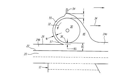
Alternatively, as shown in figures 2e and 3a-3b, dam 54 may be
placed near the surface of roller 30 to control over-the-top transfer as well as the
formation of the boundary layer 55 of m~teri~l 16 adhering to roller 30. Using areverse roller in conjunction with the dam 54 of figures 3a and 3b is a more
~,ef~ ,d embodiment than using the reverse roller by itself.
Figure 2e shows roller 30 interacting with the surface of the initially
formed building material layer 24a where accumulation 46 has formed. Dam 54 is
positioned a distance T away from the surface of roller 30. While figure 2e
generally shows dam 54 as rectangular in cross-section, dam 54 may comprise
various other shapes as long as it serves to limit the amount of accumulation 46which is allowed to pass thereby. The plef~"ed distance T is in the range of about
1/2 to about 4 mils (0.001 to 0.002 inches) with a more pler~ d range of about 1 to
2 mils. The m~tt?ri~l which passes by dam 54 forms the roller boundary layer 55.Because of boundary effects occurring as accumulation 46 meets dam
54, the reslllting thickness (W) of material passing by dam 54 may be less than
distance T thereby resulting in a roller boundary layer 55 of thickness W, wherein W
is greater than zero but equal to or less than T. The relationship between T and W
may depend on a number of factors including the m~tto.ri~ comprising the surfaces
of roller 30 and dam 54, the physical configuration and surface energies of roller 30
and dam 54, the viscosity and surface tension of the building material, and the
rotational velocity 32 of roller 30. The exact thickness W of boundary layer 55 is
CA 02210802 1997-07-18
WO 96/23647 PCT/US96/01451
26
not believed to directly impact the coating process. However, it is ~lef~l~ed that the
thickness W be less than the desired layer thickness and more preferably,
considerably less than the desired layer thickness.
In any event, the exact thickness W of the boundary layer may be
~lçtermined experimentally. Such a det.?rrnin~tion may be made in a variety of ways
including incrementally moving a dry probe toward the back side of roller 30 from a
distance until the material of boundary layer 55 is contacted. Upon contact, a
noticeable wicking-up of m~tçri~l onto the probe will occur immediately. If the
incremental positioning of the probe is calibrated relative to its separation from
roller 30, the thickness W of boundary layer 55 may be determint-~l It is postulated
that the thickness W will generally be in the range of l/2T to T, inclusive. It is also
postulated that a percentage of boundary layer 55 will remain with roller 30 as the
material in boundary layer 55 contacts the building material near the bottom 36 of
roller 30. Thus in effect, a portion of thickness W is carried along with roller 30 and
a portion is deposited onto the m~t~ri~l above the surface 22 of the last-formedobject cross-section 20 thus forming a part of the desired layer 24b.
During the recoating process, the distance between the bottom 36 of
roller 30 and the surface 22 ofthe last-formed object cross-section 20 is defined as
the roller clearance (RC). Furthermore, the distance between the bottom 36 of roller
30 and the desired working surface 26 is defined as the roller gap (RG). The plane
at which a split occurs between the material staying with roller 30 and the material
becoming part of layer 24b is defined as the "shear plane", and may be located at or
below the bottom 36 of roller 30 depending on material characteristics and othersystem parameters.
The location of this shear plane may be found experimentally by
perforrning one or more recoating operations wherein roller clearance RC is varied
starting with a roller clearance RC equal to the desired building material layerthickness and measuring the resllltin~ actual building m~tçri~l layer thickness. If the
resulting actual building m~tçri~l layer thickness is found to be equal to the desired
CA 02210802 1997-07-18
WO 96/23647 PCT/US96101451
building material layer thickness, then the shear plane is located exactly at the
bottom 36 of roller 30. Therefore, for the rotational velocity 32, translationalvelocity 34, dam spacing T, layer thickness, build temperature and resin used in the
experiment the appropliate roller clearance RC is equal to the desired building
material layer thickness and roller gap RG is equal to zero.
Alternatively, if the resulting layer thickness is less than desired, the
effective shear plane is located a distance below the bottom 36 of roller 30. In this
case, successive recoating operations may be performed where roller clearance RC is
increased and the resulting coating thicknesses measured until the desired building
material layer thickness is achieved. When performing a successive recoating
operating, it is suggested that roller clearance RC be varied by an amount equal to
the difference between the actual coating thickness achieved and desired layer
thickness. As before, once a coating thickness equal to the desired layer thickness is
achieved, one may conclude that roller clearance RC and roller gap RG have been
characterized for effective object building.
If it is determined from the initial recoating ~e,; " ,ent that the actual
measured layer thickness is greater than the desired layer thickness, additionalcoating processes and measurements may be made by varying one or more of the
recoating parameters until a coating thickness equal to the desired layer thickness
2 0 has been achieved with the apl)lopliate characterization of recoating parameters.
Two reasons which may account for a building material layer being
too thick are: (l) rotational velocity 32 being higher than translation velocity 34
while ~imtllt~neously having a shear plane located very close to roller 30 and/or (2)
- distance T between roller 30 and dam 54 being too large thereby forming too thick a
2 5 boundary layer 55. Therefore, in modifying recoating parameters in successive
reco~tin~ experiment~ to reduce the actual coating thickness to that desired, it is
suggested that the above two variables be modified.
It is generally suggested that roller clearance RC and roller gap RG
not be adjusted independently since it is believed that roller clearance RC should be
CA 02210802 1997-07-18
Wo 96/23647 PCr/US96/01451
ç~cçnti~lly equal to roller gap RG plus one layer thickness. However, if super
elevation is used during sweeping, as is typical when using a doctor blade as
explained in this application's parent application, roller clearance RC and roller gap
RG may be adjusted independently. It is possible that these parameters also be
independently adjusted for other reasons.
The thickness of the coating actually formed as compared to desired
thickness is of primary concern. Because the recoating parameters can be readilyadjusted to achieve correspondence between these thicknes~es, it is of secondaryconcern to characterize the exact relationship between T and W and between W andthe location of the shearing plane. However, knowledge of trends generally
associated with these relationships may aid in speeding the experimental
determination of ~plopliate recoating parameters.
It is ~lefell~d that boundary layer 55 formed on roller 30 provide the
shear force at the shear plane instead of roller 30 being completely or partially dried
of m~tçri~l 16 by dam 54. This is because the wetted surface of boundary layer 55
interacts with layer 24a less disruptively and more con~i~t~ntly than would a partly
dry and partly wetted surface of roller 30.
Under typical conditions it is çstim~ted that the low point 36 of roller
30 will be swept in a plane above working surface 26, i.e., the surface of the final
2 o building m~teri~l layer 24b, by a thickness, i.e., the roller gap RG, somewhere
between zero and T, inclusive. It is further anticipated that the roller gap RG will be
closer to T than zero and will be equal to the distance s~aLd~ g the shear planefrom roller 30. In any event, as roller 30 sweeps across vat 14, any m~tçri~l 16located above the shear plane will be removed leaving behind the smoothed building
2 5 m~t~ri~l layer 24b having a working surface coplanar with the desired working
surface 26.
As mentioned above, roller 30 is rotated and tr~n~l~t~cl such that the
net sum of its (a) rotational velocity, i.e., tangential velocity, 32 at or near a point 36
where roller 30 contacts working surface 26, i.e., the angular velocity of the roller
CA 02210802 1997-07-18
WO g6/23647 PCTrUS96/01451
29
multiplied by the roller radius and (b) its translational velocity 34, is greater than
either the rotational or translation velocities 32,34 taken alone. The ratio of
translational velocity to rotational velocity is preferably in the range of 1/6 to 6, but
this ratio is more preferably in the range of 1 to 4. As a specific example, theplcfe.l~_d rotational velocity 32 is 2 inches per second while the plcfe~lcd tangential
velocity 34 is 2 inches per second when Ciba-Geigy photopolymer resin SL 5131 isused.
It has been experimentally found that as viscosity decreases,
rotational velocity 32 typically increases relative to translational velocity 34.
Therefore when using plefellcd photopolymer resins SL 5170 or SL 5180 (sold by
3D Systems, Inc. of Valencia, California) which have much lower viscosities thanSL 5131, it is anticipated that pl~efcll, d translational velocities 34 be in the range of
1 to 4 inches per second while plercllcd rotational velocities 32 be in the range of 2
to 16 inches per second. The most apl)ropl;ate values for both translational androtational velocities for given circnm~t~nces can be cletermined experiment~lly. It
has furthermore been dclcllllilled experimentally that within reasonable ranges of
translational and rotational velocities, increases in rotational velocity 32 appear to
have a tapering-off differential effect.
The diameter of roller 30 is preferably between 1/4 to 3 inches, but is
2 0 more preferably between 1/2 and 2 inches, and most preferably approximately 1
inch. The ~lcfcllcd roller 30 exhibits a diameter tolerance of plus/minus 0.0002 to
0.0004 inch per linear inch, and also a m~ximum diameter variance of 0.0005 inch.
The tight ~limçn~ional tolerances of roller 30 serve to m~int~in the accuracy ofbuilding m~teri~l layers 24 and of subsequently formed object cross-sections as well
2 5 as of the overall object 12 itself.
Alternatively, roller 30 may include a knurled or other m~chined or
wrapped surface which serves to receive m~teri~l 16 thereby providing a foundation
for roller boundary layer 55. The surface of roller 30 may comprise Teflon or other
surface release agent. However, in this configuration, it is still l~crcllcd that a
CA 02210802 1997-07-18
WO 96123647 Pcrr/uss6lol45
boundary layer 55 form on roller 30 so as to ensure that the roller surface is wetted
when contacting the surface of the initial building m~teriAl layer 24a as described
above.
Referring now to figures 3a-3c, counter rotating roller embo-limPnt~
including dam 54 are further discussed. Figure 3a shows dam 54 preventing over-
the-top transfer. Dam 54 may comprise a rigid and lightweight material such as
al--minllm that will withstand accumulation 46. Dam 54 may alternatively comprise
other metal m~tçri~lc such as stainless steel, a flexible m~teri~l such as rubber or
brushes or hardened stereolithographic building materials or the like. The
l o configuration of the dam 54 may be that of a rectangular bar, a comb with teeth,
multiple 1~ n~ rlin~l or transverse elements, the various doctor blade configurations
presented in the parent application to the instant application, combinations thereof
and the like. Dam 54 may also include a Teflon or other coating on its surface to
help control the interaction between accumulation 46 and the roller surface. As a
further alternative, dam 54 may comprise a second roller (not shown) which rotates
in the opposite direction as roller 30 and mounted so that a gap which provides a
roller boundary layer 55 of desired thickness, exists therebetween.
As discussed in connection with figure 2e, dam 54 will gauge how
much material 16 stays in contact with roller 30 past dam 54. Though m~teri~l
rem~ining in contact with roller 30 preferably serves as roller boundary layer 55, in
the most pl~er~lled embol1iment~ excessive amounts of m~teri~l 16 should not pass
by dam 54 to avoid disturbing working surface 26 left in the wake of roller 30. As
discussed above, m~t~ri~l carried over the top will generally be deposited in a
Ul~irOllll manner but with excess thickness. Thus in embo-liment~ where thicker
building m~t~ri~l layers 24 are acceptable, over-the-top transfer may be effectively
used when building object 12.
The embodiment including reverse roller 30 and dam 54 may also be
used in connection with the object building techniques described in U.S. Serial No.
,
CA 02210802 1997-07-18
WO 96123647 PCT/US96/01451
08/148,544, entitled Thermal Stereolithography, filed November 8,1993, the
disclosure of which is incorporated as if fully set forth herein.
Figure 3a shows dam 54 positioned directly over roller 30. With this
configuration, accumulation 46 tends to build up as roller 30 sweeps across working
surface 26 as shown. If accurnulation 46 becomes too large, it could slump down
into vat 14 in front of roller 30 which could adversely affect the uniformity ofbuilding material layer 24b. Accordingly, care is preferably taken to monitor
accumulation 46 to prevent this occurrence. This can be done simply by ensuring
that the initial thickness of layer 24a is not so great as to overload the capacity of
roller 30 for a given rotational velocity 32 and maximum sweeping area.
At the end of the sweep, roller 30 and dam 54 may be temporarily
kept in place to avoid accumulation 46 from spreading throughout vat 14 which
could ina~plopl;ately raise working surface 26 and disturb the uniformity and
desired thickness of layer 24. After working surface 26 has been impinged by
synergistic stim~ tion, accumulation 46 may then be released so that the
accllmlll~te-1 material may be later used in the object building process. Either before
or after exposure, but preferably after, the direction of rotation and sweeping may
then be reversed and the next building material layer 24 formed.
Alternatively, the proper surface level in vat 14 for regions away
from object 12 may require that accumulation 46 be reincorporated into the volume
of m~teri~l in vat 14 prior to exposure. Therefore, the m~teri~l in accumulation 46
may be released by stopping or slowing rotational velocity 32 or by increasing the
gap T. As a further alternative, roller 30 may cease its translation motion in a side
trough (not shown) of vat 14 so that the amount of m~teri~l 16 in accum~ tion 46does not affect the surface level in vat 14.
Figure 3b shows dam 54 positioned at an angle such that
accllmlll~tion 46 is largely formed over roller 30 and not in front of it. This reduces
the risk of accumulation 46 slumping into vat 14. In any event, wherever dam 54 is
positioned relative to roller 30, it may be attached to the same frame which holds
CA 02210802 1997-07-18
Wo 96/23647 PcrluS96/01451
roller 30. Dam 54 may be attached to the frame such that its position may be varied
as a sweep occurs. For example, dam 54 may be positioned directly over roller 30 as
in figure 3b but as an accumulation 46 starts to form, dam 54 may be ~plopl;ately
moved back so that it is angled as in figure 3b. That dam 54 is movably attached to
the frame would also allow it to be moved into alt~rn~ting positions so that roller 30
could be used to sweep working surface 26 in both directions. This embodiment
may also allow an effective means to remove accumulation 46 off roller 30 after
sweeping across vat 14. With this ~ltern~tive however, care should be taken to
m~int~in a constant gap between dam 54 and roller 30 so as to m~int~in the desired
roller boundary layer 55 thickness W.
Referring now to figures 4a-4d, alternative embodiments including a
counter rotating roller 30, dam 54 and m~t~ri~l transportation device 60 are shown.
In Figure 4a, as roller 30 sweeps over working surface 26, accumulation 46 forms.
However, because dam 54 is positioned at an angle, accurnulation 46 tends to flow
over the top of roller 30 and encounters a m~teri~l transport mech~ni~m 60 such as a
screw having threads 62 as shown in figure 4b. Screw 60 may be attached to the
frame which holds roller 30 and dam 54, and preferably rotates. As the material of
accumulation 46 reaches screw 60, the material flows between threads 62 and is
transported toward one end of screw 60 due to the screw's rotation. This
2 o transportation of m~t~ri~l also reduces the size of any accumulation 46 which still
might form in front of roller 30. This in turn avoids all or a portion of such an
accllm~ tion 46 prece.ling roller 30 slumping into layer 24 due to its weight. To aid
in allowing this configuration to be used with ~ g sweeping directions, a
second transportation device (not shown) may be located below dam 54. These
2 5 material transportation devices may then ~lt~rn~te between running dry and
transporting material from layer to layer.
Preferably, screw 60 is long enough so that as material is transported
to its end, the m~t~ri~l may be redeposited into vat 14 at a location, such as the vat's
periphery, which will not hlte~reLe with the ullifo~ y of that portion of working
CA 02210802 1997-07-18
Wo 96/23647 PCrlUSs6/01451
surface 26 which is to be exposed to synergistic stim~ tion. Alternatively, the
transported m~teri~l may be directed to a reservoir (not shown) separate from vat 14.
As a further alternative, the reservoir may also be coupled to the bottom of vat 14
below working surface 26 so that working surface 26 is not disturbed upon the
m~teri~l being reintroduced into vat 14.
Figure 4c shows another embodiment where m~tçri~l of accumulation
46 is transported away. Here, as accumulation flows over the top of roller 30, it
encounters a trough 64 which may be incorporatecl into dam 54. Material enteringtrough 64 is then transported away as shown in figure 4d. Trough 64 may be angled
1 o downward toward its ends so that gravitational force facilitates materialtransportation. In any event, trough 64 is preferably long enough so that material is
redeposited into vat 14 at a location which does not hltel~ele with working surface
26 uniformity, or deposited into a separate reservoir. Again, this m~teri~l
transportation reduces the amount of m~teri~l which might accumulate in front ofroller 30, and avoids such an accumulation 46 slumping into layer 24. Other types
of m~teri~l transportation devices 60 may be used to reduce accllmlll~tion 46 such as
pumps, suction devices, and various other types of conveyor systems.
Figures Sa-Sb show another embodiment using a counter rotating
roller 30, dam 54 and dispenser 66. As shown, building m~teri~l layer 24a is
2 0 initially formed using dispenser 66 which may pull m~t~ri~l from a separate
reservoir and deposit it into vat 14 to raise working surface 26. Alternatively,dispenser 66 may extract material from vat 14 and dispenses it above object 12 in
combination with lowering object 12 one layer thickness thereby holding the
working surface 26 at an essenti~lly fixed level. Figure Sa shows the type of initial
building m~teri~l layer 24a that may be formed when dipping only a single layer
thickness where boundary 68 is formed all around the periphery of surface 22 due to
viscosity and surface energy effects which pl~v~llt material 16 from flowing, in a
sllfficiently rapid manner, over surface 22. This boundary 68 is shown in figure 5a
CA 02210802 1997-07-18
WO 96/23647 PCr/uss6/01451
34 .,
at the right side of surface 22, the left side boundary already having been elimin~tecl
as discussed below.
The embodiment of figure Sa shows dispenser 66 which cont~ins
building m~tPriAl 16 and which sweeps across working surface 26 followed by roller
30 and dam 54. Dispenser 66 provides building material 16 above the last formed
object cross-section 20, which dispensed material is then transformed into a uniform
building material layer 24b by roller 30. The material 16 dispensed by dispenser 66
is preferably extracted from vat 14 itself. Though the surface level of material 16 in
vat 14 may thereby be somewhat lowered, the surface level is restored upon the
lo dispensing as shown in figures 5a-5b. When extracting m~tPri~l from vat 14, the
material may be initially placed in a pump cylinder (not shown) or the like, and then
transferred to dispenser 66. Depending on the exact timing between filling and
emptying the pump cylinder, and filling and enlp~yillg dispenser 66, the net surface
1PVP1 Qf m~t--ri~ in vat 14 may h~ r~isg~ nr 1QW~r~r
lS As discussed above, roller 30 may translate across working surface
26 at a height above surface 22 equal to the desired thickness of the final building
m~teri~l layer 24b adjusted by some additional distance which accounts for the
thickness of material which may be redeposited from the boundary layer into layer
24b. As noted previously this additional amount is ~nticip~tP,d to be between zero
2 o and T. The height at which roller 30 tr~n~l~tes above working surface 26 may also
be adjusted for shrinkage associated with m~teri~l solidification and the other effects
discussed above. Dam 54 operates in similar fashion as described in the above
embo~imentc Dispenser 66 may also be ~tt~chP(l to the frame which holds roller 30
and dam 54. ~ltern~tively, dispenser 66 may be attached to a separate frame (notshown). As dispenser 66 provides m~tPri~l over surface 22, boundary 68 is brokenas the dispensed m~tPri~l 16 merges with that portion of building material layer 24
and working surface 26 already exi~ting as shown in figure 5a. Counter rotating
roller 30 then follows dispenser 66 to render layer 24 uniform and of desired
thickness.
-
CA 02210802 1997-07-18
W 096/23647 PCT~US96/01451
Figure Sb shows dispenser 66, roller 30 and dam 54 further along
during a sweep over initial layer 24a. Here, the boundary 68 on the right end ofsurface 22 has been elimin~tecl by the dispensed materia1 16. Also at this point,
roller 30 has smoothed a portion of layer 24a to partially form layer 24b, i.e., layer
24. Accl]m~ tion 46 is also transported over the top of roller 30 due to the angular
position of darn 54. Because accumulation 46 does not precede roller 30, its weight
will not cause it to sink or spread into layer 24. An accumulation 46 in front of
roller 30 would tend to sink more readily into a large trapped volume than it would
in a portion of layer 24 that was supported by surface 22 because in a trapped
1 0 volume, there is a larger flow path to other areas of vat 14 which provides less
resistance to flow and thus more rapid redistribution of material 16.
The frame or other means which holds roller 30, dam 54 and
dispenser 66 may be adjustable so that the order in which these components are
positioned may be reversed. This allows the dispensing and sweeping action to
occur in either the left or right directions across vat 14.
A variation to the embodiment of figures 5a-5b may involve
dispensing the building material layer 24 onto the object 12 without any dipping at
all. Here, after the last object cross-section 20 is formed, object 12 may remain
stationary and dispenser 66 may simply dispense a layer of building m~teri~l 16 over
2 o object 12 as well as over the surface of the building material 16 surrounding the top
surface 22 of the last formed object cross-section 20. Roller 30 would then smooth
the building m~teri~l layer 24 to the desired thickness while reducing or elimin~ting
any surface imperfections. In this embodiment the working surface 26 may rise with
the addition of each subsequent layer or alternatively it may remain stationary if the
2 5 entire vat 14 or floor of the vat 14 is lowered one layer thickness. In a further
alternative, dispenser 66 may dispense more than one layer thickness worth of
building m~tt-ri~l 16 and the amount in excess may be removed by an extraction
device which is either controlled in relation to the exact amount dispensed, by a
level detection system, or more preferably both.
CA 02210802 1997-07-18
WO 96/23647 PCT/US96/01451
36
Referring now to figures 5c-Sd, a preferred embodiment of dispenser
66 is shown in more detail. Dispenser 66 may include sloped walls 67 to facilitate
dispensing of m~teri~l. Dispenser 66 may also include a mesh or apertured bottom69 which delivers resin to surface 22 in a preferably uniform fashion. Figure 5dshows apertured bottom 69 in a view indicated along lines Sd-5d of figure 5c. Other
configurations of the dispensing apertures may be used including one or more slots
or other hole p~ttern~ For a building m~ten~l comprising Ciba-Geigy resin SL 5149
or SL 5154, the diameter of the ape~ es preferably ranges from about 0.020 inches
to greater than 0.100 inches to avoid clogging. However, the preferred diameter
1 o may vary according to viscosity, surface tension and other material properties.
Figures 6a-6b show the embodiment of figures Sa-Sb along with the
transportation device 60 shown in figures 4a-4b. Here, accumulated material 46
may be transported away to a location in vat 14 that does not hllelr~l~ with that
portion of working surface 26 that is to be impinged upon by synergistic stimulation,
or may be transported to a separate reservoir. As noted previously, this
transportation of material serves to further decrease any ~ccnm~ tion 46 which may
still precede roller 30 which in turn reduces the chance of accllmlll~ted m~teri~l
slumping into working surface 26 in front of roller 30.
In an ~ltern~tive embodiment, dispenser 66 may dispense material
2 o directly onto roller 30 before the dam, or if thicker coatings are desired, without
using a dam. When using a dam, it is still pl~r~lled that the separation T between
dam 54 and roller 30 is such that a boundary layer 55 of a~plopl;ate thickness is
formed so that a coating of one layer or other desired thickness is deposited in the
wake of roller 30. In this ~lt~ tive~ if dispenser 66 is located in proximity to roller
2 5 30, the rear arm of dispenser 66 may be used as the dam.
Preferably, synergistic ~timlll~tion is applied after completion of t
sweeping. If multiple sweeps are used to form layer 24, exposure may begin during
a final sweep. A delay may also be set between the completion of sweeping and
beginnin~ of exposure to allow minor surface imperfections to settle. ~lttqrn~tively,
CA 02210802 1997-07-18
Wo 96/23647 PCr/Uss6/01451
where multiple sweeps are used to form layer 24, exposure may begin prior to
completion of the first sweep.
Where greater flexibility of recoating parameters is necessary to
achieve desired coating thicknesses and uniformities, the various pararneters
discussed above may be m~ml~lly adjusted or preferably co,l,pu~el controlled during
the building of object 12. These types of adjustments might be useful when layerthickness is varied during object builclin~, when temperature changes occur during
object building, or when building materials are switched so that manual operatorintervention is not necessary. For exarnple rotational velocities, translational0 velocities, roller clearance, roller gap, and sweeping distance can be varied from
sweep to sweep. Similarly, in emborliment~ using dispenser 66, the rate at whichmaterial 16 is dispensed may be varied.
The previously discussed embodiments may be used with various
types of doctor blades in connection with roller 30 to adjust the thickness of initial
layer 24a and to otherwise help prepare building rn~t~ri~l layer 24 for forming the
next object cross-section. Reservoirs (not shown) may be located on each side of vat
14 which serve as start points and endpoints for the movement of roller 30. At these
reservoir locations, any building m~tçri~l 16 still rem~ining on roller 30 may be
removed, and any accumulation 46 formed on roller 30 and/or dam 54 may be
2 0 dumped. As with all the embo-limen~.c described ]lerein, independent liquid leveling
techniques may be used to ensure that working surface 26 exists at the plane of the
desired working surface.
As noted previously, a second roller may be added which rotates in
- the opposite direction as the first roller and which can more readily allow alternating
2 5 sweeping directions to be used. The vertical position of each roller may or may not
be adjustable so as to only allow one roller to contact the building m~teri~l during
each sweep across vat 14. In some situations it may be found useful to employ
multiple dams.
CA 02210802 1997-07-18
WO 96/23647 PCTtUS96tO1451
Additional embofliment~ may be derived by combining the te~chings
of the separately presented embo~1imentc in this section together. Further
emborliment~ may also be derived by combining the te~hin~s herein regarding
reverse rollers with the teachings regarding other recoating techniques discussed
below.
INK JET RECOATING
An alternate embodiment of the current invention involves an ink jet
print head recoater 100 as shown in figures 7a-7g. The following patents relating to
ink jets are incorporated by reference as if fully set forth herein:
U.S. PAT. TITLE TOPIC
NO.
4,383,264 Demand Drop Forming Basic technology of ink jet printinp.
Device with Interacting
Tr~n~d~lcer and Orifice
Combination
4,873,539 Phase Change Ink Jet Basic Dataproducts' ink jet technology.
Apparatus
4,833,486 Ink Jet Image Transfer Non-traditional application of ink jets.
Lithographic
4,659,383 High Molecular Weight, ~t~ri~l~ capable of being jetted.
Hot Melt Impulse Ink Jet
Ink
4,822,418 Drop on Demand Ink Jet ~t~ capable of being jetted.
Ink Compri~ing Dubutyl
Sebecate
5,021,802 Therm~lly Reversible Sol- ~t~ri~l~ capable of being jetted.
Gel Phase Change Ink or
Bubble Jet Ink
5,041,161 Semi-Solid Ink Jet and ~teri~l~ capable of being jetted.
Method of Using Sarne
CA 02210802 1997-07-18
W O 96/23647 PCT~US96/01451
39
Further background information on ink jets can be found in the
publication entitled "Ink-Jet Printing", by J. Heinzl & C.H. Hertz, in ADVANCES
IN ELECTRONICS AND ELECTRON PHYSICS Vol. 65, 1985, published by
~c~tlçmic Press, Inc. This publication is also incorporated by reference as if fully
set forth herein. In the context of this application, the term "ink jet" refers to the
dispensing of building material in the process of forming objects as opposed to
either the traditional use of dispensing ink in a selective printing process, or the use
described in U.S. patent number 4,575,330 wherein "ink jets" may be used to
dispense a reactive chemical to cause solidification of a building material in astereolithographic process.
In this embodiment, an array of ink jets dispense droplets of building
material from above the surface to be coated. Upon contacting the surface, the
individual droplets flatten out and merge with adjacent droplets to form a building
material layer. As discussed below, it has been found that layers as thin as 0.5 mil or
less may be formed which provides the opportunity to produce high resolution
objects.
As shown in figure 7a, ink jet print head recoater 100 includes ink jet
print carriage 102 having a bottom surface 104 in which an array of ink jets 106 is
configured. Recoater 100 may be mounted to the SLA by a frame (not shown) that
2 0 allows recoater 100 to translate across vat 14 and dispense building m~t.?ri~l layers
from above. Movement of recoater 100 as well as the amount of material dispensedthel~rlulll preferably occur under col~uLel control. Because ink jets may dispense a
coating of uniform and desired thickness, other recoating elements may not be
- required. For example, the use of a doctor blade may not be required to supplement
2 5 the ink jet coating formation process but in some embo.liment~, a doctor blade may
advantageously be used on periodic layers to elimin~te any accllm~ tecl errors that
may have built up. In this type of application, a doctor blade might be used, for
ex~mple7 on every 20th layer or every 200th layer. In any event, removing the need
for a doctor blade advantageously removes the problems associated with doctor
CA 02210802 1997-07-18
Wo 96/23647 PCr/US9610145
blades as discussed previously. An ink jet recoating system as described herein
which may include one or more ink jet heads and a translation system, may be
incorporated into current stereolithography m~chines in place of the doctor blade
recoating system.
A flexible feeder line 108 for supplying m~t~.ri~l to ink jets 106 may
be coupled to carriage 102. Carriage 102 may include internal passageways (not
shown) to direct building m~teri~l 16 received from line 108 to each ink jet 106.
Alternatively, feeder line 108 may itself branch into multiple lines, each connected
to an ink jet 106.
0 As shown in figure 7a, feeder line 108 may extend from vat 14 and
include p D p 110 to provide m~t~ri~l 16 directly from vat 14 to recoater 100.
~lt~m~tively, material may be supplied from one or more other sources such as
separate reservoirs thereby allowing portions of object 12 to be selectively formed of
dirr~ " m~teri~l.s This provides that object 12 may include portions which
conduct electricity, are flexible to provide a hinge or other flexible object feature, or
are of different colors, hardnesses or have other chemical or physical differences.
This also provides that interior portions of object 12 may be coated with a "non-
building" m~teti~l such as wax which can be removed to form an investment casting
mold.
Carriage 102 may be long enough to span a significant portion of vat
14. In this configuration, a single carriage 102 may provide a building material layer
24 from a single traverse of vat 14. Alternatively, a plurality of carriages 102 may
be used to traverse dirrelellt portions of vat 14 in a band-wise fashion. For example,
four (4) carriages 102 may be used, one in each quadrant of vat 14. As a further~ltt.m~tive, a single carriage 102 may traverse over dirr~lel~l portions of vat 14 until
a sufficient building m~t~ri~l layer 24 is formed. In any event, after layer 24 is
formed, carriage(s) 102 are preferably located at the periphery of vat 14 to avoid
r~;,ing with the source of synergistic stim~ tion 28. ~ltt?rn~tively as with thecounter rotating roller embotliment~ described above, carriage 102 and any
CA 02210802 1997-07-18
,
W O 96/23647 PCTAUS96/01451
positioning h~dw~e still located within the building region of the vat may simply
be located outside the region to be exposed when forming the next object cross-
section from the dispensed layer 24.
Referring now to figures 7b-7d, alternate configurations for the ink
jet 106 array of bottom surface 104 are shown. Ink jet 106 arrays may include any
number of ink jets 106 to increase the volumetric flow of m~tpTi~l dispensed which
in turn is preferable for forming larger objects. Increased volumetric flow may also
lessen the time required to form successive building material layers thereby
decreasing overall object build time.
0 In any event and as noted above, each ink jet 106 dispenses droplets
of material which upon contacting the surface to be coated, flatten and merge
together. Accordingly, ink jets 106 are preferably spaced closely enough so thatdroplets dispensed therefrom are also close enough to merge upon contacting the
surface. The effective spacing between ink jets 106 may also be varied by the
positioning of carriage 102 as it traverses vat 14. As shown in figure 7d for
example, the ink jet 106 configuration is similar to that of figure 7b but the ~ngling
of carriage 102 in relation to its direction of translation, effectively reduces the
distance between ink jets 106.
The o~lhllul-l spacing of ink jets 106 varies with factors such as the
2 0 size of droplets to be dispensed, the type of building m~tPri~l used, the desired
resolution of the object to be formed as well as other factors. First, the spacing of
ink jets 106 may generally increase with increasing droplet size. This is because
when flattened upon c~nt~cting the surface to be coated, larger droplets cover a- larger area and thus will merge with other large droplets though spaced further away.
Second, as m~t~ri~l viscosity ofthe building m~teri~l increases, the
orifices 1 12 of ink jets 106 through which the m~tt~.ri~l passes upon being dispensed,
must also generally increase. This is primarily because materials with higher
viscosities may generally tend to clog ink jets 106 having small orifices 112.
Because orifices 112 are thus larger with more viscous materials, the droplets will be
CA 02210802 1997-07-18
W 096123647 PCTrUS96/01451
42 f
larger thereby allowing ink jets 106 to be spaced further apart. However, this must
be balanced against the fact that droplets of more viscous materials will flatten and
merge more slowly. Accordingly, orifices 112 are preferably still spaced closelyenough to permit droplet merger.
In any event, the viscosity of m~teri~l 16 should not exceed the
operating requirements of ink jets 106. High resolution ink jet dispensers typically
require the viscosity of material 16 to be less than S0 centipoise, and preferably less
than 30 centipoise at operating temperature. Mediurn resolution ink jet dispensers
typically require that material 16 viscosity be less than 500 centipoise. Thoughmaterial 16 may be heated to lower its viscosity, care must be taken where material
l 6 comprises a photo or thermal polymer because acceptable levels of heating islimited by the stability of the monomers contained therein and practical monomers
are limited to temp~l~Lu-es of less than one hundred (lO0) degrees Centigrade.
Furthermore, if m~teri~l 16 is dispensed and solidified at an elevated temperature, it
may distort even more upon solidifying due to thermal shrinkage. However, this
limitation is mitigated to the extent that the m~tçri~l 16 may cool before
soli-lific~tion
Third, objects requiring higher resolution are generally formed from
thinner building material layers and to form thinner layers, smaller droplets are
2 o generally used. Accordingly, ink jets 106 are preferably spaced closer together and
at least closely enough so that the dispensed droplets merge when fl~tte~d upon
contacting the surface to thereby rapidly form a uniform building m~tçri~l layer 24.
Besides providing for higher resolution objects, smaller droplets dispensed frommore closely spaced ink jets 106 may also decrease object build time. That is,
2 5 droplets which are closely spaced will require less time to level out after contacting
the surface and merging. This enables working surface 26 to form more quickly
thereby decreasing the time required before synergistic stim~ tion may be applied.
~r~tpr~ having lower viscosity and surface tension also level out more quickly
after contacting surface and thus also help reduce build time.
CA 02210802 1997-07-18
W 09~23647 PCTAUS96/01451
43
J Ink jet recoating may decrease object build time regardless of which
droplet size is used because the downward force of the "rain" of dispensed droplets
is relatively small so as to avoid disturbing the last formed object cross-section 20 as
it solidifies. For example, where the last formed object cross-section 20 comprises
an irradiated photopolymer, a certain amount of time may be required to pass before
the photopolymer has sufficiently cured for layer 20 to exhibit the strength of a solid
or pseudo-solid. If building material layer 24is formed over layer 20 before a
sufficient cure time has passed, the force of material 16 flowing over layer 20 such
as that which occurs during deep dipping, may actually "wash away" the essentially
still-liquid object cross-section 20. However, because the force of ink jet droplet
rain is relatively small, layer 20 will generally not be washed away even though the
time necess~ry for some minimum cure has not passed. Accordingly, layers of
object 12 may be formed in more rapid succession.
Several commercially available ink jet print heads 100 are suitable for
use in this embodiment. An ink jet print head having an orifice 112 diameter of 2
mils is model no. HDS 96 m~nnf~ctured by Spectra, Inc. of Hanover, New
Hampshire. This ink jet may dispense a droplet that flattens upon cont~cting thesurface to be coated to a disk having a thickness between one-half (0.5) and one ( l )
mil, and a diameter between four (4) to six (6) mils. To achieve a disk of these2 o ~limen~ions~ it is ~l~re,l~d that bottom surface 104 of the ink jet head be about 1 to 2
mm above the top surface 22 of the last formed object cross-section 20.
The preferred embodiment includes a carriage 102 with two (2) of the
Spectra HDS 96 print heads, each print head comprising 96 individual jets or orifices
- 1 12 in their bottom surfaces 104. Dispensing is controlled whereby carriage 102
tr~n~l~tes at 56 inches per second, and each ink jet array 106 discharges droplets at a
rate of 16,000 droplets per second amounting to 300 droplets discharged per inch. In
this configuration, a 0.0005 inch layer may be created over a 12" by 12" area inapproximately 5 seconds.
CA 02210802 1997-07-18
WO 96/23647 PCTJUS~6/01451
44
An ink jet print head capable of jetting droplets having a diameter
between six (6) to ten (10) mils is Model No. INZX050050CC manufactured by Lee
Corporation of Westbrook, Connecticut which fires droplets at a m~ximllm rate of1,200 droplets per second. Though larger droplet sizes may decrease resolution,
carriages 102 dispensing larger droplets are less expensive, may dispense m~t~ri~l at
a greater volumetric flow rate which is beneficial when forming thicker layers, and
may typically dispense a wider range of materials because larger viscosities may be
accommodated. Dataproducts of Woodland Hills, California also m~nllf~c*lres ink
jet heads that may be used with this ink jet recoating technique.
1 o Several examples showing the relationship between thickness of layer
24 and drop size are now discussed to illustrate the parameters of interest. First,
with the Spectra HDS 96 print head providing droplets of about 2.2 mil diameters, a
"drop" volume of 100 picoliters (lOOE-12 liters) results based on the relationship
that volume = (4/3)~r3. If the 100 picoliters is printed at a rate 300 x 300 drops per
inch, the resulting layer 24 is about 0.55 mils. Second, with the Lee
INZX050050CC print head providing droplets of about 10 mils, the drop volume is
1,800 picoliters. At a drop rate of 100 x 100 drops per inch, the resl-ltin~ layer 24 is
about 1.1 mils.
Embo-liment~ of ink jet recoating reflecting the above concepts and
2 0 advantages are ~ cll~ecl below. Referring again to figure 7a, the top surface 22 of
the last formed object cross-section 20 is typically at the same level as the working
surface 26, i.e., the surface of the rest of m~teri~l 16 in vat 14. Building m~teri~l
layer 24 may then be formed by each ink jet 106 providing a discharge 120 of
m~tPri~l 16 as recoater 100 tr~n~l~tes across vat 14.
A first embodiment involves the configuration whereby the m~teri~l
16 supplied to ink jet print head 100 comes from vat 14. Here, as shown in figure
7a, recoater 100 has already traversed that portion of vat 14 to the right of surface
22. However, the level of m~t~ l 16 remains subst~nti~lly even with surface 22
because as m~teri~l 16 is drawn from vat 14 by feeder line 108, recoater 100
CA 02210802 1997-07-18
Wo 96/23647 PCT/USg6101451
essentially replaces this m~teri~l 16 thereby keeping the volume of material 16 in vat
14 con~t~nt
As recoater 100 traverses surface 22, discharges 120 form building
m~teri~l layer 24 of the desired thickness. However, for layer 24 thicknesses in the
one-half (O.S) to ten (10) mil range which is of practical interest in
stereolithography, the surface tension and viscosity of material 16 effectively
immobilizes the material at the ends of layer 24 such that it will not flow over the
ends of surface 22 and back into vat 14. Thus, the volume of material 16 in vat 14
decreases slightly by an amount equal to the volurne of layer 24. As recoater 100
1 0 traverses the portion of vat 14 to the left of surface 22, the volume of material 16
again remains subst~nti~lly constant because the withdrawn material is replaced by
discharges 120.
After recoater 100 has traversed vat 14, the surface 126 of the
m~teri~l 16 dispensed on surface 22 is higher than the rest of vat 14 by the total of
(a) the desired thickness of building m~tPri~l layer 24 and (b) the height whichworking surface 26 may have been lowered due to the lack of repleni~hmPnt into vat
14 as surface 22 was traversed. Accordingly, to form a uniform working surface 26,
platform 18 may be lowered by this c-lm~ tive height to result in the configuration
shown in figure 7e. At this point, print head 100 is preferably located at the
2 o periphery of vat 14 and layer 24 is exposed to synergistic stimlll~tion from a source
of synergistic stim~ tion 28.
Material may be dispensed by ink jet recoater 100 in multiple passes
over surface 22 so that a sufficient amount of m~t~ri~l to form layers of the desired
- thickness has been dispensed. Furthermore, interleaving of droplet dispensing
2 5 points may occur between multiple passes of the print head 100 to ensure that a
more ul~irOllll coating is dispensed. Also to decrease dispensing time, additional
printing heads may be added to the dispensing system thereby allowing faster
dispensing rates.
CA 02210802 1997-07-18
W096/23647 PCT/IUS96/01451
46 L
If the as~ ~lion is made that there is no need to dispense material
outside the area encomp~se(l by the previously solidified object cross-section 20,
and any associated trapped volumes, an alternative embodiment is possible where
dispensing time may be reduced. As noted in the previous embodiment, under
~rop~;ate conditions the dispensing of m~t~ri~l onto regions away from surface 22
nomin~lly results in little gain. Accordingly, an ~ltçrn~tive procedure for use in the
foregoing embodiment involves simply dispensing m~tçti~l from ink jet head lOO
only onto surface 22 and any associated trapped volume areas. After dispensing in
this selective manner, the previously formed object cross-section 20 may be lowered
one layer thickness. This lowering process properly positions the previously formed
cross-section 20 relative to the desired working surface 26 and also brings the upper
surface of the layer 24 over surface 22 to the same level as the rest of the material 16
in vat 14. Therefore, after a short delay wherein material in the boundary regions of
the coating 24 above the previously formed cross-section 20 merges with the
m~t~ri~l 16 ~ c~nt to these regions, exposure to form the next cross-section of the
three--limen~ional object may occur. Since less m~tçri~l is being dispensed by the
ink jet heads l 00, the reco~ting time for this embodiment may be reduced.
An alternate embodiment is shown in figure 7f and is similar to the
previous embofliment.~ except that platform 18 is first lowered a distance equal to the
2 0 desired thickn~s.~ of building m~teti~l layer 24 prior to dispensing m~t~ri~l from the
ink jet dispenser l 00. This results in boundary 68 forming around surface 22
wherein viscosity and surface tension effects typically prevent the material 16
surrounding surface 22 from flowing thereon. Recoater lOO may then be tr~n~l~te(l
across vat 14 at only those locations where a surface of object 12 exists, i.e., over
surface 22 including any trapped volumes. Building m~teti~l layer 24 may then bedispensed to the desired thickness, upon the completion of which a ul~ifolm working
surface 26 is formed without need for a short delay to allow merging of m~tçri~lacross boundaries 68 as was discussed in connection with the previous embodiment.
CA 02210802 1997-07-18
WO 96/23647 PCI/US96/01451
47
In any event, providing a short delay after dispensing may be used and may be
desired in some circllm~t~nces.
RECOATING CRITICAL AREAS
In an alternate embodiment, much of the time savings associated with
dispensing material only in selected locations, i.e., only over the surface 22 of the
last-formed object cross-section 20 and any trapped volumes, is m~int~ined whilesimultaneously ensuring that material is dispensed in all required locations.
As noted above in association with the counter rotating roller
technique, only regions that are deep and connected by large flow paths will readily
achieve a uniform level. Therefore, to ensure that shallow regions and regions
poorly connected to the bulk of m~tçri~l l6 in the vat 14 are properly coated, the ink
jet dispensers l 00 preferably dispense material onto these regions. As noted above
in connection with the counter rotating roller embodiment, the depth of a region for
it to be considered shallow and possibly troublesome depends on the viscosity and
surface energy of the building material and on the surface energy of transformedbuilding m~tçri~l And as also noted, shallow regions generally have depths of less
than about 40 mils (l mm) to about 240 mils (6 mrn). Therefore in order to ensure
adequate dispensing, it is preferred that ink jet heads l00 dispense m~t~ri~l above all
shallow regions having a depth less than 40 to 240 mils. For m~teri~l~ with
2 o relatively low viscosities, e.g., l to l 00 centipoise, it is estim~ted that the shallow
regions will include regions having a depth of no more than 40 mils or less. Formaterials with moderate viscosities, e.g., l00 to 1,000 centipoise, it is estim~ted that
the shallow regions will include regions shallower than about 40 to l20 mils. When
using m~teri~l~ with moderately high viscosities, e.g. l,000 to l0,000 centipoise, the
2 5 shallow regions may include regions having depths of up to l20 to 240 mils or more.
Under these conditions, layer or cross-sectional comparisons may be
y~,~r~l.l.ed on the data descli~live of the cross-sections of object l2 to deterrnine
exactly what regions for each layer should be considered shallow regions. Layer
CA 02210802 1997-07-18
W096/23647 PCT~US96/01451
48
comparison techniques are disclosed in co-pending U.S. Patent Application SerialNos.08/233,027 and 08/259,333, filed on April 25,1994 and June 16, 1994,
respectively. These applications are incorporated by reference as if fully set forth
herein.
To cl~termine which regions are shallow and thus possibly
troublesome, one may first cletermine or specify the depth at which a region is to be
considered shallow. One may then divide the shallow region depth by the layer
thickness to be used in forming object 12. The resulting quotient rounded upwardrepresents the number of layers N that should be used in the layer collll)al;sonprocess. Next, the Boolean union of the regions contained in the previously
solidified cross-section 20 and the regions contained in all N-1 immediately
procee-ling cross-sections is ~letermin~l The result of this union operation
represents the shallow regions for the current layer which are preferably coated by
ink jet heads 100. The det~rmin~tion of shallow regions for each layer may be
~et~rrnine(l prior to beginning formation of object 12 or ~ltern~tively ~letennined as
needed during object formation. A variety of Boolean operations may be used in
deriving the desired data inclu-ling union operations (+), differencing operations (-),
intersection operations (x), as well as other operations.
The m~teri~l in regions that are isolated from or poorly connected to
2 0 the buLk of m~teri~l 16 in vat 14, may also be ~letermin~l These type of regions
include trapped volumes and regions that are "near" trapped volumes. There are
various methods for en~l.ring that trapped volume regions and near trapped volume
regions are included with shallow regions in clefining the area to be coated by ink jet
printhe~l 100. The most str~iPlll r ,l~d approach is to pelrullll a Boolean union of
all regions included on any previous cross-section ofthe object, connected objects
and supports. The result of this Boolean union defines the region to be coated in
forming building m~tt-ri~l layer 24.
A simple modification to this calculation involves including a switch
which may be set by the SLA operator for indicating whether or not object 12
~ ==
CA 02210802 1997-07-18
wo 96/23647 Pcr/uss6lol45
49
co~ ins trapped volumes and/or near trapped volumes. Based on the setting of this
switch, determin~tion of which trapped areas are to be coated for each layer will be
derived from either the N previously formed object cross-sections or all previously
formed object cross-sections. Depending on the configuration of the object, having
the switch set to a "no trapped volumes" setting will result in coating of an amount
of m~teri~l less than or equal to that which would otherwise be coated if the switch
were oppositely set.
As another ~ltern~tive to avoid di~ficulties that may be caused by
trapped volumes, the maximum extents of each object cross-section may be used to(let~rmine a rectangular minimllm dispensing region. To determine the net
dispensing region to form a given layer, the Boolean union of the minimum
rectangular dispensing region from each of the immPrli~tely prece~1in~ N cross-
sections may be formed. This Boolean union represents the net dispensing region.A fully ~ltom~ted technique may also be impl~mented to derive a ~ " area to
be coated when forming each layer.
For given m~t~ri~l~, the depths to be associated with shallow regions
may be dçtermined by e~c- ;...ent~tion. One may perform recoating tests over a
cross-section with a relatively large cross-section:~l area and critical circle. The
cross-sectional area and critical circle of the cross-section should be selected to
2 0 correspond to the cross-sectional rlimen~ions of the objects which will be typically
built on the SLA. For example, if one intends to build prim~rily small objects, e.g.,
objects having cross-sections with critical circles with radii less than 1/2 inch, then a
test surface with a critical circle of radius 1/2 inch may be used. Alternatively, if
- one intends to build objects which have cross-sectional critical circles with radii as
2 5 large as 4 inches, then a test surface of similar size should be used. One may then
dip the surface into the liquid varying depths and ~letermine the time required for
m~teri~l to flow over the cross-section for the dirfelclll depths. The minimum depth
for which a coating is formed in a reasonably small period of time, e.g. less than 2 to
5 seconds, may define the depth of the shallow regions.
CA 02210802 1997-07-18
WO 96/23647 PCT/US96/01451
It is possible to ~lrOllll one or more inverse erosion routines, i.e.,
e~r~n~ion routines, on regions which are ~let~rmined to require ink jet dispensing in
order to expand these regions some specified amount to ensure adequate coating by
the ink jet print heads 100. This is especially so when it is desired to avoid precise
registration between ink jet dispensing locations when forming layers and exposure
locations when forming cross-sections. Erosion routines and inverse erosion
routines are described in several ofthe previously incorporated U.S. Patent
Applications including Serial Nos. 08/233,027; 08/233,026; and 08/259,333.
Further disclosure may also be found in U.S. Patent Application Serial No.
o 08/299,475, filed 8/31/94 by Hull et al., which application is incorporated by
reference as if fully set forth herein. In essence, inverse erosion routines are similar
to line width, cure width, or beam width compensation techniques except that thecompensation amount is negative which results in an expansion of the cross-
sectional area as opposed to the a contraction of the region.
The above noted erosion techniques and Boolean operations may be
performed on boundary vectors ~lefinin~ regions or ~ltçrn~tively may be performed
on software or hal.lw~; configured bit maps (pixel maps) (lçfining the regions. In
any event, ink jet control is preferably based on bit map represent~tions of theregions to be coated.
2 o Referring to figure 7g, an ~ i v~ embodiment involving ink jet
reco~ting is shown which may reduce object 12 build time. Here, the portion of
layer 24 that was formed first is exposed to synergistic stimul~tion while
~imlllt~n~ously, the rest of layer 24 is formed. The object 12 is also lowered into the
surrounding liquid bath at a~plopl;~le times as ~ cl-~e(l below. Also in this
2 5 ~ltçrn~tive, ink jet recoater 100 may begin dispensing layer 24 over the top surface
22 ofthe last formed object cross-section 20 before surface 22 has been completely
exposed to synergistic stim~ tion. That is, ink jet recoater 100 may recoat overportions of surface 22 as they are exposed, instead of waiting until the entire surface
22 has been exposed.
CA 02210802 1997-07-18
W O 96123647 PCTrUS96101451
Figure 7g shows surface 22 from above and divided into sections A
and B. The software controlling the source 28 of synergistic stimulation preferably
directs source 28 to expose all those portions of surface 22 in section A beforeproceerling to section B. After section A has been exposed, recoater 100 may
immediately form the next layer 24 thereon while section B is being exposed. In
similar fashion, after section B has been exposed, recoater 100 may form the next
layer 24 thereon while the source 28 of synergistic stimulation is exposing those
portions of layer 24 in section A that had just been recoated. This process may
altern~tin~ly occur such that object 12 build time is reduced.
So as not to disturb the liquid level, i.e., working surface 26, of
section A as it is exposed to synergistic stimul~tion, the m~teri~l 16 being dispensed
over section B of surface 22 may be supplied from a reservoir (not shown) separate
from vat 14. After section B is exposed to synergistic stimul~tinn, platform 18 may
then be lowered one layer or other desired thickness and the volume of m~teri~l 16
in vat 14 may be corrected by directing a volume of material 16 displaced by thelowering of platform 18, to the S~ ~dLt~ reservoir.
An alternative embodiment involving ink jet recoating involves
object 12 being formed in a vat 14 which is not filled with m~teri~l 16 when object
12 is initially formed. Here, a building m~teri~l layer 24 over the entire vat 14 is
2 0 dispensed and then selectively exposed to synergistic stim~ tion. Platforrn 18 then
remains stationary and successive layers 24 are formed over the entire vat 14 and
selectively exposed to synergistic stimnl~tion. In this manner, working surface 26
rises as object 12 is built. To m~int~in the proper distance between working surface
- 26 and the source 28 of synergistic stim~ tion, source 28 may also be raised as each
2 5 ~llcces.~ive layer 24 is formed.
To .~ recoating errors due to jets mi~firin~ or due to
dirr~l~nces in the volurne dispensed by individual jets, each jet may be controlled to
dispense m~tPri~l at dirrtre.~ rates. Additional emborliment~ that account for the
non-uniformity in surface level which may result when forrning layers and forming
CA 02210802 1997-07-18
WO 96/23647 PCT/US96/01451
cross-sections based on dispensing exact quantities of m~teri~l over previously
formed cross-sectinn~ as discussed in other portions hereof may also be used in
connection with the foregoing.
Additional embo-liment.~ may be derived by combining the te~chin~
of separately presented ink jet embo~liment~ in this section together. Further
embodiments may also be derived by combining the te~ching~ herein regarding ink
jet recoating with the te~hing.c regarding other recoating techniques discussed
above and below.
SL~NG RECOAT~NG
o Another embodiment of the current invention is shown in figures 8a-
8n and involves an applicator 210 which is swept over working surface 26 and
which includes a rotating or spinning element that slings or otherwise ejects building
material from the applicator 210. The building m~teri~l is slung or ejected onto at
least the last-formed object cross-section 20 and typically onto at least a portion of
working surface 26. A ~l~r~ d embodiment is shown in figure 8a which is a side
view of applicator 210 forming a building m~teri~l layer 24 by elinging buildingm~tt~.ri~l spray 211 onto at least the top surface 22 ofthe last-formed object cross-
section 20.
Applicator 210 may include envelope 212 which houses dispensing
2 o roller 213 that is preferably positioned with its axis perpendicular to the direction
217 in which applicator 210 tr~nel~t~s Other angular orientations with respect to
the sweeping direction may be used. Roller 213 may comprise a circular bar
mounted to axle 216 as depicted in figure 8b, or a series of closely spaced wheels
215 coupled to an axle 216 as depicted in figure 8c. Roller 213 preferably extends at
2 5 least the width of the object 12 being formed and more preferably extends over
ellbst~nti~lly the entire width of working surface 26. ~ltern~tively, if side chambers
exist on vat 14, applicator 210 and roller 213 may extend beyond the width of vat
14. Roller 213 may be spun or otherwise driven by a motor (not shown).
-
CA 02210802 1997-07-18
.
W O 96/23647 PCT~USg6/01451
53
A row of nozzles 219, or a slit housed by envelope 212, spaced along
the length of roller 213 may deliver building m~tçri~l 16 at or near the surface of
roller 213. Preferably, substantially equal quantities of m~teri~l are deliveredthrough each nozzle 219 so that each wheel 215 or section of roller 213 ejects
subst~nti~lly equal quantities of m~tçri~l onto surface 22 or working surface 26.
~ltçrn~tively, and as discussed below, m~teri~l may be delivered near the axis of
roller 213, e.g., via axle 216, which m~teri~l travels outward to the roller surface
where it is ejected.
When material is delivered at or near the surface of roller 213, at least
l o moderately selective ejection of material may occur particularly if roller 213 rotates
at a high enough speed such that the material delivered by nozzles 219 clings toroller 213 for less than one full rotation thereof. Another technique for obtaining
selective directional ~lin~in~ is to use a cam or other non-cylindrical rotating roller
or wheel, or an off-axis rotating cylindrical roller or wheel, in conjunction with
pulsed and selectively timed application of m~teri~l to the roller or wheel. Here the
application of material is preferably timed so that material is applied at the same
point on roller 213 or wheel 215 on sllccçs.~ive rotations, and the m~teri~l is slung
before roller 213 or wheel 215 completes a full rotation. To minimi7e imb~l~nces in
forces acting on the wheel or roller assembly be~ring~, the roller or wheel assembly
2 o may be designed so that its center of gravity corresponds to the axis of rotation.
This may be accompli~he(l by a~lopliately weighing portions of roller 213 or wheel
215, or by c~ in~ the "m~tçri~ llnrhing" regions of each segment along the length
of roller 213 or wheel 215 to vary around its circumference.
- It is pl~r~ d that m~teri~l delivered near the surface of roller 213 be
deposited with a velocity component parallel to the tangential velocity of roller 213
so as to aid roller 213 in receiving the m~teri~l In any event, a portion of them~teri~l ejected from roller 213 is directed toward and through aperture 224 in
envelope 212 and is thus deposited onto surface 22 on working surface 26 to form a
building material layer 24 as applicator 210 is swept across vat 14. Envelope 212
CA 02210802 1997-07-18
.
WO 96/23647 PCT/US96/01451
54
may include flanges 225 which prevent m~t~ l 16 intercepted by envelope 212
from falling onto surface 22 or working surface 26, or otherwise impeding spray
211.
In circllm~t~nces where m~t~ l is delivered, e.g., by nozzles 219, to
the roller surface, material ejected from roller 213 is ejected tangentially to the roller
surface. Where m~teri~l is delivered at or near the center of roller 213 such as via
axle 216, the material may possess a radial velocity component as it reaches theroller surface. However, such material is typically ejected substantially tangentially
to the roller surface because the radial velocity component is relatively small
1 0 compared to the tangential velocity component. However, if the radial and
tangential velocity components of material delivered at or near the roller center are
controlled, material may be ejected from the roller surface at a desired angle which
is between tangential and radial.
In any event, it is plere~led that roller 213 be located fully within
envelope 212 as depicted in figure 8a so that the size and location of apertures 224
and flanges 225 may dictate the dimensions and direction of spray 211. To this end,
the size and orientation of the apertures 224 and flanges 225 may be adjusted toachieve the desired configuration of spray 211. Flanges 225 are preferably
configured to ensure that m~teri~l which is not ejected directly through apertures 224
2 o does not later indirectly or residually pass through apertures 224 as a result of
dripping from envelope 212.
As shown in figure 8n envelope 212 may include additional material
traps 226 and m~teri~l removal elements 228 to further reduce the possibility ofuncontrolled release of m~teri~l Flanges 225 and any additional traps 226 and
2 5 removal devices 228 thus preferably ~l~velll a non-uniform ejection of material
which could otherwise result from dripping or the like, thereby potentially causing
regions of n~ if olllli~y in layer 24 being formed. As such, flanges 225 are
preferably configured to minimi7~ the chance that ejected material strikes theiroutward faces and thereafter drips down onto surface 22 or working surface 26. This
CA 02210802 1997-07-18
WO g6/23647 PCT/US96/01451
minimi7~tion may occur by orienting flanges 225 so that they are either parallel to
the direction of mAteri~l ejection, or are at an angle to the path of m~teri~l ejection,
as shown in figure 8a, such that ejected m~teri~l strikes the inside of flanges 225.
Any residual material that may still strike the outward faces of flanges 225 may be
picked up and removed by a~lo~l;ate use of supplemental flanges and/or material
removal devices, e.g., suction or drainage devices.
The configuration of envelope 212 may also be modified from that
depicted in figure 8a to better enable removal and/or trapping of extraneous material.
As mentioned above, envelope 212 may be symmetrically designed, or otherwise,
1 0 with downward sloping surfaces exten~ling from flanges 225. An example of this
type of envelope 212 configuration is depicted in figure 8n and further includesadditional traps 226 and removal holes 228.
As mentioned above, as an alternative to dispensing m~teri~l at or
near the roller surface, m~teri~l may be delivered to the center of roller 213 or
wheels 215 such as via axle 216. The m~teri~l may then travel radially outward to
the roller surface where it is then ejected. To this end axle 216 may comprise ahollow perforated tube which is filled with building material. The material may
migrate from axle 216 through the p~lrordLions and passageways (see figure 8e)
through the roller 213 or wheels 215, and to the surface of roller 213.
2 o Roller 213 may alternatively be wrapped with one or more wires (not
shown) or may have a knurled, m~chined or other p~tterned surface which may helpdefine the portions of roller 213 from which spray 211 may be ejected. In this
manner, roller 213 may include "high" points such as points 221 in figure 8g. High
- points 221 facilitate spray 211 being .ulirOllll because material 16 will be attracted to
and ejected therefrom. Alternatively, roller 213 or wheels 215 may comprise a
porous m~te.ri~l 222 or may be surfaced with a porous m~teri~l 222 as depicted in
figure 8d. In this configuration, material delivered near the axis of roller 213 or
wheels 215 may work its way through the porous m~teri~l to the roller surface for
subsequent ejection. Alternatively, the porous m~teri~l may allow roller 213 or
-
CA 02210802 1997-07-18
,
WO 96/23647 P~ U~ 45
56
wheels 215 to absorb m~teri~l that is dispensed at or near the roller surface such as
by nozles 219. Alternatively, as shown in figure 8e, roller 213 or wheels 215 may
include a plurality of radially running holes 223 which extend from the axial region
to the roller surface thereby forming channels for material flow.
An ~ltern~tive embodiment of sling recoating which involves slinging
building m~teri~l from a spinning dispenser is shown in figures 8f-8j. Figure 8fshows a side sectional view of applicator 210 which is forming a building material
layer 24 by slin~ing a building material spray 211 onto the top surface 22 of the last
formed object cross-section 20. Applicator 210 may again include envelope 212
1 0 which may be attached to the SLA by a frame (not shown) to provide translation
across surface 22. Preferably, applicator 210 is computer controlled.
Envelope 212 houses a plurality of spray nozles 219 in a row which
deliver building m~tPri~l 16 onto a corresponding row of spinning wheel assemblies
240. A feeder line (not shown) extPn~ling from vat 14 or another source may be used
to supply material 16 to applicator 210 which then distributes m~teri~l 16 to each
nozle 219.
Envelope 212 is preferably large enough to house a row of about ten
(10) to forty (40) corresponding nozles 219 and spinning wheel assemblies 240.
Preferably, this number of nozles 219 and wheel assemblies 240 may be housed
2 o within an envelope 212 having a length of about ten (10) inches. Longer or shorter
envelopes 212, and more or fewer nozles 219 and wheel assemblies 240 may be
used to recoat larger or smaller surfaces 22, or multiple passes over dir~erelltportions of surface 22 may be made by a shorter applicator 210, or by a plurality of
applicators 210. When using multiple passes or multiple applicators, interleaving of
2 5 locations of dispensing may be used to the help uniformity of building material
layers 24. Furthermore, if a shorter applicator 210 or a plurality of shorter
applicators are used, randomization or ~ItPrn~te seqmPncing of regions coated byparticular wheel assemblies 240 may be used to help alleviate any thickness
anomalies that might build up from slight differences in quantities or m~t~ri~l
CA 022l0802 l997-07-l8
W O 96/23647 PCT~US96/01451
dispensed by each wheel assembly 240 which might otherwise occur if each wheel
assembly 240 always coated the same locations.
Each spinning wheel assembly 240 may comprise wheel 242 that is
rotated by axle 244 which is driven by a motor 246. Preferably, wheel 242 and axle
244 comprise a lightweight material such as alllminllm. Wheels 242 are preferably
driven at substantially constant speed to reduce variations in the volume of material
dispensed because of failure to operate wheel assemblies 240 in a steady state mode.
However it is ~lcr~"cd that when desired, the speed at which wheels 242 rotate, and
the speed at which applicator 210 tr~n~l~t~s across vat 14 may be varied to provide
0 the desired thickness of layer 24. It is most pl~fell~d that this variability be
implementPd on a sweep-by-sweep basis.
Envelope 212 may include individual apertures 224 through which
material from each wheel 218 may be dispensed. Since material will typically be
ejected from wheels 242 in more of a tangential manner than a radial manner as
depicted in figure 8h, it is pl~;r~lled that wheels 242 not protrude beyond envelope
212. Figure 8h depicts one of the wheels 242 rotating in a counter clockwise
direction and material being slung from wheel 242 in directions which are
ess~nti~lly tangential to the surface at the point of d~Lule.
Figure 8i is a sectional view down axles 244 and depicts three of the
2 o pluralit,v of wheels 242 rotating in counter clockwise direction 260 and dispensing
material 16 in all directions. Only material dispensed in the directions of apertures
224 are actually ejected from applicator 210 to working surface 26 or surface 22.
Material dispensed in all other directions works its way into troughs 262 which may
- be formed in part by flanges 225. The m~t~ l in troughs 262 may be recycled to be
2 5 redispensed onto wheels 242 by a pump or other device (not shown). As can be
seen, flanges 225 point tangentially toward their re.spective wheels and allow
m~teri~l dispensed directly through apertures 224 to exit envelope 212.
As can be seen from figure 8i the upper portion of envelope 212 may
include curved sections 264 so that m~teri~l slung in this direction will not merely
CA 02210802 1997-07-18
Wo 96/23647 Pcrluss6lol45
hit envelope 212 and drip dow,lw~d. Tn.~te~-l upon hitting envelope 212 the
ejection force of this material will cause it to travel around curved sections 264 and
into troughs 262. The inner surface of envelope 212 may be coated with a releaseagent to facilitate the flow of m~tçri~l into troughs 262. ~It~rn~tively, the inner
surface of envelope 212 may be coated with a porous m~tçri~l so that dispensed
material clings to envelope 212 wherein capillary action is used to hold the material
in place as it flows to troughs 262.
As can also be seen in figure 8i, envelope 212 preferably includes
shields 266 to inhibit m~teri~l dispensed from one wheel 242 from striking an
lo adjacent wheel 242. Shields 266 may also prevent material being inadvertently
dispensed through the an adjacent wheel's aperture 224. Shields 266 may connect to
the bottom of troughs 262 in order to separately m~int~in the material ejected from
each wheel. This material separation may aid in having each wheel 242 dispense
substantially equal amounts of m~teri~l through each wheel's respective aperture224. This m~int~.n~nr.e of m~t~riAl separation may be combined with the feeAb~ckmech~ni~m.~ described below to ensure that steady state dispensing is m~int~ined at a
desired level. In any event, if a known amount of m~tçri~l is dispensed to each
wheel and the dirrerellce between the amount of trapped material and the dispensed
m~teri~l is detçrminerl~ one may obtain a first order approximation of the amount of
2 0 m~tçri~l dispensed by each wheel assembly 240.
Figure 8i also shows that because the material is ejected tangentially
from wheels 242, apertures 224 are preferably located off-center relative to wheels
242. Furthermore, the spacing between wheels 242, the size and locations of
~lLules 224 and the distance from the bottom 276 of applicator 210 to working
surface 26 are preferably coordinated to provide a layer 24 of unirollll and desired
thickness. To this end, various alternatives may aid in the formation of desiredlayers 24: 1) the use of a non-symmetric dispensing pattern may be useful since all
points of ejection are not at the same distance from working surface 26 and are not
oriented at the same angle, 2) each cell of applicator 210 may consist of two wheels
CA 02210802 1997-07-18
WO 96123647 PCT/US96/014Sl
. 59
242 rotating in opposite directions thereby allowing apertures 224 to be centered
with wheels 242, 3) the direction of spinning of successive wheels 242 may
alternate, 4) a second or further applicator 210 with wheels 242 located at interlacing
points to those in the other applicators, and 5) individual wheels may be located at
dirr~lclll vertical h~ightc, e.g., adjacent wheels, which are rotating in the same
direction, may be displaced vertically from one another with a~p.opliate aperture
adjustment to allow more symmetric material dispensing.
Alternatively, but less yl~f~ d for the reasons noted above, envelope
212 may include a continuous slit ext~ntlin~ for most of its length through which all
wheels 218 dispense material. As with the embodiment above, nozzles 219 may be
positioned so that m~t~ri~l 16 is dispensed to the inner or outer portion of wheels
242. However, it is most prefe~led that dispensing occurs to the outer portion of
wheels 215 wherein the material is not allowed to cling to wheel 215 for a full
rotation so as to allow more selective material dispensing at given orientations.
The m~teri~l caught by envelope 212 generally flows downward.
Flanges 225 may be positioned above apertures 224 to direct any downward-flowingm~t~ri~l 16 around a~ ;s 224 and to the bottom of envelope 212 where
accumulation 270 forms. This accllm~ ted building m~t~ri~l may be directed
through a line (not shown) back to vat 14 or other source of building material 16 for
2 o later reuse. Accordingly, this embodiment provides for efficient use of building
m~tt?ri~l 16 which reduces the cost of operating the SLA.
Applicator 210 tr~n~l~tes in the X-direction 217 across surface 22 as
it emits building material sprays 211. The individual sprays 211 provided by wheels
242 form an aggregate spray which sweeps over surface 22 thereby forming building
2 5 m~t~ri~l layer 24. Forming layer 24 in this manner overcomes the problem of air
pockets and bubbles associated with curtain coaters.
In order to m~int~in steady state conditions, once object building has
begun, it is ~rerelled that wheels 242 constantly spin and that m~teri~l 16 is
con.~t~ntly sprayed. Even where the source of material 16 is vat 14, constant
CA 02210802 1997-07-18
WO 96/23647 PCrtUS96/01451
spraying does not detriment~lly alter the volume of m~teri~l 16 in vat 14, e.g.,misplace working surface 26 in relation to the source 28 of synergistic stim~ tion,
because as m~trri~l 16 is drawn into envelope 212, it is also being sprayed back into
vat 14 in the form of building m~tçri~l layer 24. Accordingly, there is no
appreciable net change in the volume of m~tçri~l 16 in vat 14. In a given steadystate circumstance, the amount of m~teri~l rem~ining in envelope 212 may be
different than for other circllmct~nces. This could result in a variation in material in
the vat which may be accommodated for by use of an independent liquid leveling
system as discussed previously.
Applicator 210 may accelerate and decelerate at the beginning and
end of its translation over each successive sweep such that the amount of material 16
sprayed per unit area may change thereby altering the uniformity of layer 24.
However, it is plcfcllcd that this acceleration/deceleration occur near the periphery
of vat 14 and away from the object being built. Alternatively, but less plcf~llcd due
1 5 to the loss of steady state conditions, the speed at which wheels 242 rotate may also
be slowed during these periods to decrease the amount of m~teri~l 16 dispensed
from applicator 210 to compensate for the applicator's slower speed.
Though other speeds are possible, it is plcfellcd that wheels 242
rotate at a speed of about 1,000 to 10,000 rpm and that wheels 242 have a diameter
2 o between 1/2 and 2 inches, more preferably between 1/2 and 1 inch and mostpreferably about 3/4 inches. As shown in figure 8g, wheel 242 may include a
serrated edge comprising a plurality of points 221 circurnferentially spaced which
act as l~llnching points for the m~teri~l to leave spinning wheel 242. This allows
material 16 to experience greater force when re~r.hing the l~lmching points which
2 5 results in a more uniform release of the droplets and thereby formation of a more
uniform layer 24.
In this recoating embodiment it is most ~lcrcllcd to use a
photopolymerizable resin that tends to heal small imperfections, e.g. SL 5149, SL
5154 and LMB 5463, all m~mlf~rtllred by Ciba Geigy. Droplets of these resins tend
CA 02210802 1997-07-18
Wo 96/23647 PCrlUSs6/ol4s
61
to quickly merge into one another upon touching thereby leaving no trace of a border
between them. Thus, as sprays 211 from each wheel 242 contact surface 22, the
dispensed building material quickly adjusts to smooth out any irregularities thereby
forming a uniform building material layer 24.
It should also be noted that the techniques to correct errors
accllml-l~ted over the building of successive object cross-sections, errors from non-
uniformly applied layers and errors from shrinkage which are discussed in
connection with the other embodiments of this application may also be used in
connection with this embodiment. For example, applicator 210 may dispense an
1 0 additional building material layer 24 every nth layer to correct any overall height
deficiency. Also, the bottom surface 276 of envelope 212 may be used as a doctorblade to correct for irregularities in thickness. This doctor blade type use of the
envelope 212 may occur in conjunction with an over coating process, e.g. deep dip,
on periodic layers, e.g. every 10th to 200th layer, to correct for any acc -mlll~te~
error built up over previously formed object cross-sections. Alternatively, the
overcoating process could involve dispensing an excess quantity of material fromthe sling device, which excess may be trimmed down using a doctor blade. Also, the
sweeping speed of applicator 210 may be increased or decreased to compensate forthickness errors in previous layers.
2 o An alternative to the configuration shown in figure 8f is shown in
figure 8j. As with the embodiment of figure 8a, the size and positioning of apertures
224 directly control the ~limen~ions of sprays 211 as well as the direction in which
sprays 211 contact surface 22. In this manner, a precisely-controlled spray 211 may
be directed at surface 22. Also, to avoid clogging of apertures 224 or ~linging of
excess material from apertures 224, guides 280 may be mounted in envelope 212 todirect any m~teri~l hllelc~ ed by envelope 212, away from apertures 224.
This embodiment includes a recycling arrangement for supplying
m~teri~l 16 to wheels 242 as now described. Guides 280 may direct the intercepted
material to accllmlll~tion 270 near the bottom of envelope 212. Feeder line 282 and
CA 02210802 1997-07-18
WO 96/23647 PCr/US96/01451
62
valve 284 may m~int~in material 16 in accumulation 270 at a desired level by either c
removing excess m~tçri~l or adding material as needed. A pump such as a peristaltic
pump (not shown) and a level detection system may be included to control the level
of accumulation 270. Impeller 286 is attached to wheel 242 as shown and also dips
into accumulation 270 so that its blades 287 may transport m~t~ri~l 16 that had been
previously supplied from spray nozzle 219, back to wheel 242. Upon re?,ching
wheel 242, this m~tçri~l 16 is again transported to the wheel's 242 perimeter orpoints 221 where it is then ejected theler~ol.l. As an alternative, impeller 286 may
comprise a screw mounted inside a cylinder which may be used to draw material up1 0 to the center of wheel 242. As with wheel 215 of figure 8e, wheel 242 of figure 8j
may include holes running radially from the axial region to the perimeter region of
wheel 242. In this case, m~teri~l pulled up from accumulation 270 passes throughthe radial lines and is then ejected from wheel 242.
As spraying starts, accumulation 270 may be provided with m~teri~l
from that intercepted by envelope 212 as well as incoming line 282. As
accumulation 270 rises, more m~tPri~l 16 will be transported by impeller 286 to
wheel 242 such that spray 211 is also increased. This increase in spray 211 willcontinue until a steady state is reached where the rate of material incoming to
applicator 210, e.g., through nozzles 219 and/or line 282, is equal to the rate at
2 o which m~teri~l is dispensed though aperture 224.
In such a steady state, the rate at which m~t~ri~l 16 is supplied to
wheel 242 by impeller 286 and/or nozzle 219 is known and colls~ , and thus the
rate of dispensing through aperture 224 is known. And because the rate at which
applicator 210 traverses over surface 22 is known, the resulting thickness of building
2 5 m~teri~l layer 24 may be calculated. Because of this foregoing relationship, a
desired building m~tçri~l layer 24 thickness may be achieved by regulating
translation of applicator 210 and the rate at which m~teri~l 16 is supplied thereto,
i.e., the volume of spray out of applicator 210 is equal to the volume of material 16
supplied thereto.
CA 02210802 1997-07-18
,
Wo 96/23647 PCr/US96/01451
63
Alternatively, after impeller 286 dispenses material 16 onto wheel
242, guides 280 may direct the intercepted material 16 back down into vat 14. Inthis situation, if the rate at which m~teri~l 16 is dispensed onto wheel 242 is known
and constant, and the fraction of this material 16 being dispensed through aperture
224 is known and constant, and the transport rate of applicator 210 is known andconstant, once again the thickness of building material layer 24 will be known.
In the foregoing embodiments involving impeller 286, material 16
from vat 14 may be pumped continuously to applicator 210 because after a steady
state is achieved, the rate at which the material 16 is removed from vat 14 equals the
1 o rate at which it is dispensed back into vat 14. As an option to precisely control the
amount of material introduced into applicator 210 e.g., through nozles 219 and line
232, a pump with a variable speed motor (not shown) may be used along with a
pressure sensor (not shown) before a final flow restrictor (not shown) as material 16
is dispensed. To this end, a servo controller (not shown) can then be used to control
the motor to provide constant plCS~ , which in turn will provide a constant flowrate of material.
An alternative to rotationally driven sling recoating is shown in figure
8k and includes a series of piston powered dispensers 290 instead of spinning wheels
242 or roller 213. Material 16 may be supplied to pistons 290 by feeder line 292.
2 0 The source of m~teri~l 16 may be vat 14, accumulation 270 of intercepted material
16 or some other reservoir. Preferably, pistons 290 are small and operate at a high
frequency to avoid a discernible cyclical dispensing of material 16 that might result
in a wavy or otherwise nonunirc~l~ll building m~t~r;~l layer 24. The m~t~ri~l leaving
piston dispensers 290 is sent through a nozle which dispenses m~tt?ri~l onto
2 5 working surface 26.
An allcllldlive embodiment involving sling recoating is shown in
figures 81-8m wherein applicator 210 may remain translationally stationary whiledispensing spray 211 over surface 22 to form building m~t~ri~l layer 24. In thisembodiment, applicator 210 operates by use of wheels 242 but the roller 213 of
CA 02210802 1997-07-18
WO 96/23647 PCI/US96/01451
64
figures 8a-8e or the piston of figure 8k may also be used. Envelope 212 may include
a mount 294 which is rotatably mounted to frame 296 at pivot point 298. Frame 296
may be coupled to the SLA.
As shown in figure 8m, applicator 210 may rotate clockwise about
pivot point 298 to form building material layer 24. To form the next building
material layer 24, applicator 210 may rotate counterclockwise for efficient operation.
Preferably, after a building material layer 24 has been formed, applicator 210 is
moved by frame 296 to a peripheral location of vat 14 to avoid interfering with
layer's 24 exposure to synergistic stimulation. Alternatively, the dispenser may be
1 o located at the edge of vat 14 and may rotate to the side to dispense layer 24. The
dispensing of layer 24 may occur in a single rotation, or a back and forth rotation of
multiple rotations.
So that layer 24 is uniform, the volumetric flow of spray 211 may be
adjusted throughout the rotation of applicator 210 so that flow decreases or thesweeping velocity increases as applicator 210 rotates towards the position at which it
dispenses spray 211 vertically downward, and so that the spray increases or velocity
decreases as applicator 210 rotates beyond vertical dispensing.
An alternative to the embodiment of figures 81-8m involves mounting
a plurality of rotating applicators 210 in various locations over vat 14, such as
2 0 mounting an applicator 210 over each quadrant of vat 14. In this ~ltern~tive, the
amount of rotating required by each applicator 210 is reduced thereby easing thecontrol over adjustment of sprays 211.
Further embo~liments may also be derived by cornbining the
te~chings of separately presented sling recoating embotliment~, or by combining the
tç~chings of sling recoating with the te~rhings regarding the other recoating
techniques described above and below.
CA 02210802 1997-07-18
WO g6/23647 PCTrUS96/01451
APPLICATOR BAR RE~OATING
Referring now to figures 9a-9n, an alternative embodiment of the
current invention is shown whereby applicator 310 simultaneously applies and
smoothes a building material layer 24. In a first pl~ftl,ed embodiment of this
technique, after the last forrned object cross-section 20 has been formed by
selectively exposing the building material to synergistic stim~ tion~ object 12 iS
dipped one layer thickness, or other desired thiclcness, below the desired working
surface 26 of building material l 6. During the exposure process, applicator 310 iS at
least partially filled with material 16 and after the exposure process, applicator 3 l 0
is swept at or slightly above the desired working surface 26 while dispensing
material from opening 315 to forrn building material layer 24. After the dispensing
of material 16, the vertical position ofthe upper surface 22 ofthe last formed object
cross-section 20 may be adjusted if necessary so that it is essentially one layer or
other desired thickness below the desired working surface 26.
Applicator 3 l0 may be coupled to the SLA by a frame and drive
system (not shown) so that it may be swept horizontally at or slightly above working
surface 26. Applicator 310 is preferably colll~ulel controlled for precise formation
of building m~tçri~l layer 24. It is ~ f~l,cd that applicator 3 l 0 be swept only as far
as needed (as opposed to sweeping applicator 310 across the entire vat 14) to ensure
2 o formation of an adequate building material layer 24 and to ensure a free path for
exposure to synergistic stimlll~tion from source 28. The requirements for this
enhanced sweeping criteria were discussed above in association with the counter
rotating roller and ink jet dispenser embo(1iment~
After complete formation of building material layer 24 exposure of
the layer occurs to form a subsequent cross-section of object 12. After formation of
the subsequent object cross-section, the process of forming a successive building
material layer 24 and forming a successive object cross-section is repeated.
However, in this repetition of steps, applicator 3 l 0 may be swept in opposite
directions as it dispenses m~tçri~l to form successive layers 24. Repetition of the
CA 02210802 1997-07-18
W096/23647 PCTrUS96/01451
66
cross-section and layer forming steps continlles, with altçrn~ting directions ofsweeping, until object formation is completed.
In this first ~crcl.cd embodiment, the resin volume in applicator 310
is m~int~ined by vacuum pump 321, pressure regulator 323, and vacuum feed line
325. The application of vacuum through line 325 into the upper portion of cavity327 of applicator 310 causes a pressure differential to occur between the inside of
cavity 327 and the region outside applicator 310. Applicator 310 is sealed with the
exception of one or more openings near its top and with the further exception ofopening 315 at its bottom. The openings near the top of applicator 310 provide for
0 connection to vacuum feed line 325, while the opening at the bottom forms a slit for
applicator 310 to receive and dispense building material 16.
Since applicator 310 is located at or near the desired working surface
26 and since building m~teri~l 16 will contact the bottom of applicator 310 by
spontaneous events or by design, a meniscus 331 will form as shown in figure 9a
bridging any gap between working surface 26 and the bottom of applicator 310.
Since meniscus 331 seals the applicator 310 bottom, as the pressure dirr~clllialforms due to application of a vacuum at the top of the applicator 310, building
m~teri~l will be drawn up into applicator 310 until the plcs~u,c dirre.enlial outside
and inside applicator 310 iS zero. Pressure regulator 323 preferably allows a
2 o controlled ~les~ulc dirrt;rcl.lial to be formed to control the amount of material 16
drawn into applicator 310.
This controlled amount of m~teri~l 16 iS specified to be at least as
great as the m~imum amount of material 16 necess~ y to form the next layer 24.
~sllming that layer 24 will be formed over the entire area of vat 14, the volume of
this maximum amount of material 16 iS equal to the thickness of the layer 24 to be
formed multiplied by the cross-sectional area of vat 14 holding building material 16.
However, it is p~crc~lcd that the controlled amount of m~t~ri~l 16 contained by
applicator 310 be significantly greater than the anticipated m~xi~ l amount to
form layer 24. The resulting excess ensures that applicator 310 will not run dry
CA 02210802 1997-07-18
W Og6/23647 PCTrUS96101451
67
during a sweep and thereby ensures that meniscus 331 will not be broken. This isimportant because a break in meniscus 331 could lead to at least a momentary loss in
vacuum pressure which in turn could result in the inability to rapidly replenish the
material dispensed by applicator 310 when preparing to form the next layer 24.
Though it is possible to shut off the active mahlt~ ce of vacuum during sweeping,
in the plef~lled embodiment the application of vacuum continues even during
sweeping.
Preferably, the length 322 of applicator 310 as shown in figure 9c is
slightly less than the inside width of vat 14 or at least slightly extends beyond the
maximum extent of object 12. Figure 9a depicts applicator 310 to the left of object
12 shortly after object 12 has been dipped one layer thickness below working surface
26 by elevator 17 which is coupled to platform 1~. As can be seen in figure 9a,
material 16 is drawn to a significant height in cavity 327. Figure 9b depicts
applicator 310 after it has been swept almost the full distance across the last formed
object cross-section 20. As can be seen in figure 9b the height of the resin column in
cavity 327 has decreased due to the volume of m~teri~ll6 dispensed during
sweeping. Since the sum of the volume of material in applicator 310 and vat 14isçcsenti~lly a constant arnount (ignoring shrink~ge of cured material and volume
changes due to aperture fluctuations), if the amount of material in applicator 310
2 o varies, so will the amount and associated surface level of material in vat 14.
Therefore it is l.ler~lled that the amount of resin in applicator 310
remain relatively constant during exposure. It is further plef~ d that in
independent liquid level device be used in conjunction with vat 14. As discussed~ previously and as can be ascertained by colll~hlg figures 9a and 9b, an adequate
2 5 volume of m~t~ri~lis preferably contained within applicator 310 prior to beginnin~ a
sweep. Otherwise dry spots or coatings of inadequate thickness may result.
Applicator 310 includes flanges 312 which in turn include angled portions as shown
in figures 9a-9b that help reduce any leading edge bulge problems.
CA 02210802 1997-07-18
W 096/23647 PCTrUS96/01451
68
Figure 9c depicts a perspective view of the p~cr~;l,cd applicator 310.
As can be seen from the combination of figures 9a, 9b and 9c, applicator 310 maycomprise an elongated bar with a hollow interior. Figure 9c also depicts severalholes 326 along the top of applicator 310 which represent locations at which one or
more vacuum feed lines 325 may be connected. Preferably, care is taken to ensure a
tight fit between lines 325 and holes 326 to prevent undue loss of vacuum pressure.
Figure 9c also depicts viewing port 335 which is formed by making a hole in
applicator 310 and inct~lling a window thereover to preserve the vacuum. From
viewing port 335, the height of building material 16 in applicator 310 may be
visually determine~l
With the exception that no holes are shown in the top of the
applicator, figures 9d-9f depict the l~cfc,l~d applicator 310 of figures 9a-9c from
end, side and bottom views. Each of these views depicts dimensions of an applicator
of the type described herein as implemented on an SLA-250 stereolithographic
a~p~dLus as sold by 3D Systems, Inc. of Valencia, California. Holes 337 depict
mounting holes for ~tt~chin~ applicator 310 to the e~ictin~ doctor blade mount on
3D Systems' SLA 250 stereolithography a~p~dLus. The presently l~lerc,l.,d vacuumpump for use with the applicator of figures 9d-9f is Model No.3020 sold by Apollo
pumps of Ontario, California. For the applicator of figure 9d it is ~,efe"cd that the
vacuum regulator supply a stable vacuum ~lcs~ulc sufficient to pull m~teri~l 16
about 1/2" up into applicator 310. Also for the applicator of figure 9d, the volume of
material 16 typically drawn up into it is approximately 20 to 25 mL, whereas thevoll.me of m~t~ri~l in a single 0.15 mm layer produced by an SLA 250 is
a~pro~i",ately 9 to 12 mL. A plcr~l~dplcS~-ILc regulator involves the use of a
bleeder valve that may be adjusted to allow a small but continuous supply of air to
bleed into applicator 310 thereby providing an equilibrium vacuum pressure that is
sufficient to pull material into the applicator 310 the desired amount.
In experimentin3~ with the above plcfelled applicator 310, various
layer 24 thicknesses have been formed. From these experiment~, layer thicknesses
CA 02210802 1997-07-18
WOg6/23647 PCT~US96101451
69
in the range of at least 2 mils to l 0 mils, inclusive, may be achieved, with the most
cfellcd thiçkn~sses cullelllly being 4 to 6 mils, inclusive. It is also anticipated that
applicator 310 of the pl~fell~d embodiment may be used to form layers 24 as thin as
0.5 to l mil when a building m~teri~l exhibiting uniform properties is used. It is
further anticipated that applicator 310 of the ~lere,led embodiment is not strictly
subject to an upper limit on layer thickness as long as sufficient material is available
within cavity 327.
Figure 9g depicts a side view of applicator 3 l 0 spaced above working
surface 26 by a small amount. This spacing between the bottom of applicator 3 l 0
and desired working surface 26 during sweeping is analogous to the "blade gap"
associated with the use of doctor blades and is herein referred to as the "applicator
gap" (AG). In the above ~r~r~lled embodiment, stereolithography resin SL 5 l 70 is
most preferred but it is believed that other stereolithography resins offered by 3D
Systems, Inc. can be used as well. Successful layer-forming experiments have been
pclrolllled with applicator gaps varying from 3 to lO mils. Though the lower limit
on applicator gap AG is zero, this has been found to be generally less than optimal
due to leading edge bulge problems and increased potential for collisions between
applicator 310 and object 12 being formed.
The upper limit on applicator gap AG is the m~xilnl,... height above
2 o working surface 26 at which a reliable m~onieC~le 33 l may be m~int~in~cl between
applicator 3 l 0 and working surface 26. This maximum applicator gap AG is
typically somewhere below 30 to 35 mils but is dependent on the building material
16 used. The optimal value of applicator gap AG is the smallest gap at which
- collisions between applicator 310 and object 12 are essentially non-e~ietent and
2 5 leading edge bulge is not a problem. It is believed that this optimal value is
dependent on the properties ofthe m~t~ri~l 16 being used such as viscosity, as well
as the configuration of applicator 310. The present most pler~lled values of
applicator gap are between 5 and 8 mils, inclusive.
CA 02210802 1997-07-18
WO 96123647 PCI~/US96/01451
Figure 9h depicts the spacing between the bottom of applicator 310
and the upper surface 20 of the last formed object cross-section 20 during sweeping.
This spacing is known as the "applicator clearance" AC and is analogous to the
"blade clearance" associated with the use of a doctor blade. Typical applicator
clearances AC range from about one (1) layer thickness to about three (3) layer
thicknes~es. The presently most plerell~d range of applicator clearances AC is
between 1.1 and 1.7 layer thicknPs~es and the most ~-lefelled value is ~;ullcllLly about
1.4 layer thicknesses.
As can be ascertained from the above ranges of applicator gap and
clearance, the upper surface of the last formed object layer may be located at aposition above or below its desired position for exposing a layer of material to form
a next cross-section of the object. Thus, depending on the exact values of gap and
clearance used the object may need to be raised or lowered slightly after sweeping
with applicator 310 to complete the coating process so that a next object cross-section can be formed.
Experiment~ with sweeping speeds of applicator 310 of the
configuration depicted in figures 9d-9f, indicate that the most pl~fc..ed speeds, when
using SL 5170 resin, are in the range of about 1 to 4 inches per second, inclusive.
However, these experiments further indicate that higher sweeping speeds may be
2 o acceptable if the SLA or other a~Lus is de~igned to translate applicator 310 at
higher speeds without inducing excessive vibration in the SLA. It has further been
found that for a given applicator 310 configuration, as viscosity of building material
16 increases sweeping speeds are preferably slowed to allow sufficient time for
m~teri~l 16 to be dispensed. A sweeping speed is considered to be too high if
excessive material 16 is being scooped from above previously formed object cross-
sections.
The following benefits from the foregoing embodiment have been
observed during ~ e~ ent~tion: (1) significantly enhanced accuracy in building
material layers 24, (2) post sweeping delays have been drastically reduced or
CA 02210802 1997-07-18
WO 96/23647 PCrlUS96/01451
completely elimin~ted, (3) predip delays have been drastically reduced or elimin~te~l
and (4) generalized recoating parameters regardless of object 12 configuration have
been usable.
Additionally, it is anticipated that the foregoing recoating
embodiment exerts lower forces on object 12 during the recoating process which
advantageously results in an overall reduction in object 12 distortion. This reduction
in force exerted on object 12 also provides that previously formed cross-sections
such as last-formed object cross-section 20 require less structural modulus to retain
their integrity. The resulting reduction in need for immediate green part structural
modulus leads to broader process latitude in deriving build parameters and also eases
development efforts necessary in finding suitable object building materials, e.g.,
epoxy resins, by easing acceptance criteria. It is further believed that the building
material layers 24 formed by this p~rel.ed embodiment provide self-correction ofminor errors in thickness from layer-to-layer, e.g., due to shrinkage or simply due to
coating errors, which reduces or elimin~tes the need for a periodic accllmnl~ted error
checking and/or correction. In any event such a periodic process may still be used if
desired, e.g., deep dip and sweep off every Nth layer.
In summary this p.~r~l.ed applicator 310 embodiment performs two
functions at the same time: (1) it applies m~teri~l 16 to initially form building
2 o m~tPri~l layer 24a and (2) eimult~neously smoothes layer 24a to form a final
building material layer 24 having a working surface essçnti~lly coplanar with the
desired working surface 26. This ~rer~.lcd applicator embodiment also: (1) forrns
more accurate layers of m~teri~l, (2) significantly reduces recoating time and
(3) allows the use of generalized, i.e. readily autornatable, recoating parameters. It is
2 5 further anticipated that further reductions in build time may be achieved by exposing
the first-dispensed portion of layer 24 to synergistic etim~ tion to form a next object
cross-section while applicator 310 is still dispensing the latter-dispensed portion of
layer 24 over the last-formed object cross-section 20.
CA 02210802 1997-07-18
Wo 96/23647 Pcrluss6/01451
Figures 9i and 9j depict a second ~ fcllcd embodiment of applicator
310. In this embodiment, cavity 327 of applicator 310 is not filled with building
m~teri~l 16 via vacuum pump 321, regulator 323 and vacuum tube 325. Tn~te~cl,
m~teri~l 16 is m~int~ined in cavity 327 via pump 340, extraction tube 342 and fill
tube 344. In this embodiment, material 16 is drawn to pump 340 from applicator
310 by suction through extraction tube 342 and dispensed from pump 340 through
tube 344 back into vat 14. The arrows in the figures indicate the direction of material
flow in the tubes. To avoid bubble formation from fill tube 344 as it supplies
building material 16 back into vat 14, the entry location of fill tube 344 into building
m~tçri~l 16 may be surrounded by a fence, wall or bubble catcher (not shown).
When used in conjunction with applicator 310 of figures 9d-9f and
with SL 5170 stereolithography resin, the presently ~ler~lled pump 340 is a
diaphragm or piston pump, Model No. 50000-072, sold by Cole Parrner. This pump
has a controllable flow rate up to a m;.xi",l~.n flow of 0.3 gallons per hour. In a
given application, the required flow rate may be greater than the amount of material
comprising the number of layers to be formed in a given time period. However, it is
plerelled that the flow rate be significantly larger than this amount to preserve the
integrity of meniscus 331. To further preserve meniscus 331, it is plefe~led to let
pump 340 run continuously so as to c~ nct~ntly pull m~tPri~l 16 through applicator
310 and redeposit it into vat 14 regardless whether or not applicator 310 is sweeping.
A perict~ltic pump may be more ~l~relled in the long term to
minimi7e cleaning time and problems when the building m~t~ri~l to be used in theSLA is changed. ~Itçrn~tively, the SLA may include separate pumps and tubing foreach building m~teri~l to be used. Separate applicators 310 may also be used for2 5 each building m~tçri~l
In this embodiment, a quantity of m~t~ri~l 16 sufficient to form
building material layer 24 may be pumped to applicator 310 during exposure of the
last formed object cross-section 20. ~ltern~tively, m~teri~l 16 may be pumped toapplicator 310 as it forms building m~t~ l layer 24.
CA 02210802 1997-07-18
W Og6/23647 PCTrUS96/01451
73
Figure 9k depicts an alternate embodiment applicator 310 which
includes a bleeder valve 350 that is preferably electrically act~l~tecl, e.g., by a
solenoid and col~lpuler controlled to open and close as comm~n~led Before
sweeping, applicator 310 may be loaded with material 16 by lowering applicator 310
in the downward direction of arrow 352 partially into building material 16 while at
the same time opening bleeder valve 350. After material 16 has filled applicator 310
to the desired level, bleeder valve 150 may be closed and applicator 310 may be
raised vertically in the upward direction of arrow 352, out of material 16 so that its
lower surface is located above the desired working surface 26 by the desired
applicator gap AG.
Since applicator 310 m~int~in~ contact with the body of building
material 16 in vat 14 via meniscus 331, and since applicator 310 is completely
sealed due to the closure of valve 350, material 16 remains trapped in applicator 310.
After loading applicator 310, it may be swept ho~ on~ally above the previously
formed object cross-section 20, as depicted by arrow 354, to form a next building
material layer 24.
In an ~ltern~tive embodiment to that depicted in figures 9i and 9j, the
direction of m~teri~l pu~ illg may be reversed. So long as the bottom of slottedapplicator 310 is located within the meniscus connecting the applicator and the
working surface it is believed acceptable coatings will be formed so long as them~teri~l dispensing rate is matched to the sweeping speed to yield a coating of
desired thickness over the last formed object cross-section 20 and over any other
shallow regions. Applicator 310 may still continue to withdraw and dispense
material away from the shallow regions when not sweeping.
Figure 91 depicts an alternative embodiment of applicator 310. In this
embo(lim~nt applicator 310 may comprise several components which may move
relative to one another including: upper element 311, flanges 312 and end caps 313
(the end cap at the far end of applicator 310 is not shown). As with the previous
embo-liment~, these components form a sealed applicator 310. In this embo-liment,
CA 02210802 1997-07-18
,
W096f23647 PCTfUS96101451
74
applicator 310 is filled with m~tçri~l 16 by (1) reducing the volume of cavity 327
before or while applicator 310 is in contact with material 16 and then (2) expanding
the volume of cavity 327 while the bottom of applicator 310 is in contact with
building material 16. The contraction and expansion of cavity 327 may be
accomplished by moving flanges 312 closer and further away as flanges 312 slide
along upper element 311 and end caps 313. The expansion and contraction of
flanges 312 is preferably ~ rolllled under colll~ulel control lltili~ing solenoids,
electric motors with ball screws, pneumatic pressure or the like. Since during the
expansion applicator 310 is sealed by tight fits between its components, the only
way to balance the growing vacuum in cavity 327 is to draw m~teri~l 16 into
applicator 310. Once sufficient material 16 is drawn into applicator 310, expansion
may stop and sweeping and associated material deposition may begin.
Figure 9m depicts an end view of an alternative applicator 310 which
may also contract and expand. Here, contraction and expansion of cavity 327 may
be accomplished by moving upper element 314 down before or while applicator 310
contacts material 16, and up after applicator 310 iS in contact with m~teri~l 16thereby creating a vacuum and filling cavity 327. As applicator 310 sweeps across
vat 14, upper element 311 may again be moved dowllw~d thereby creating a force
on m~tçri~l 16 to f~ilit~te dispensing.
2 o In an alternate embodiment, a sponge of other wicking material (not
shown) may be inserted in the applicators 310 of figures 9a, 9i, 91 and 9m.
Referring to figure 9k this sponge may also be used to wick m~tPri~l up into
applicator 310 while valve 350 is open thereby elimin~ting the need to lower
applicator 310 into building m~tt~.ri~l 16 in order to fill cavity 327. Similarly, the
2 5 sponge may be utilized in the embo-liment~ of figures 91-9m wherein the drawing of
m~tçri~l 16 into the sponge occurs by e~p~n-ling cavity 327 as described above.
Dispensing from an applicator 310 including the sponge may occur while sweeping
with applicator 310 sealed. ~ltern~tively, sweeping may occur with valve 350 open,
with end caps 313 removed or with cavity 327 being contr~cte~l The wicking or
CA 02210802 1997-07-18
W Og6123647 PCTrUS961014
capillary capabilities of the sponge elimin~tçs the need for sweeping with a sealed
applicator. Dirrelel~t wicking materials may be useful for dirr~lent building
m~tçri~l.s so that the wicking rate and ability to dispense are optimi7e~1 When using
a sponge, it is pler~ d that the sponge be positioned within applicator 310 so that
the bottom of the sponge is slightly above the bottom of flanges 312.
An example of an alternative applicator 3 l O based on the use of
wicking forces is depicted in figure 9n. In this alternative the wicking elementincludes a number of closely spaced inner flanges 364 that are positioned withinflanges 312 and upper element 311 and that are sized ap~lol)liately to allow capillary
forces to draw material up into applicator 310. The distance 362 between inner
flanges 364 may vary with material viscosity but where material 16 comprises a
photopolymerizable resin such as SL 5170, a gap 362 of 0.05 to 0.150 inches is
pl~:r~,lled. To facilitate absorption, the surfaces of inner flanges 364 may be coated
with a porous m~tçri~l to enhance the capillary action of flanges 364. Inner flanges
364 may also be moved vertically so they can be filled by immersion into building
m~teri~l 16 in vat 14. Alternatively material 16 may be fed between inner flanges
364 by ~ P~
An alternate embodiment of applicator 310 including a roller 370
located between flanges 312 is shown in figure 9o. Here, roller 370 may comprise a
cylinder which is coupled to applicator 310 at its ends by axle 372. Roller 370 is
preferably driven so that it rotates with a tangential speed m~tching the translational
speed of the applicator 310 thereby elimin~tin~ any horizontal motion of the bottom
of roller 370 relative to working surface 26. Alternatively roller 370 may spin freely
- so that it may rotate as applicator 310 tr~ncl~te~ along working surface 26. Roller
370 is preferably made of al~.",i~l.. but may ~ltern~tively comprise a sponge-like
m~teri~l or may have a sponge-like coating or surface. As a further ~ltçrn~tive,roller 370 may have a knurled or other m~chinecl surface which provides more
surface area to receive material 16.
CA 02210802 1997-07-18
W 096t23647 PCTnUS96/01451
76
The bottom of roller 370 may be located at or above the bottom of
flanges 312 and is preferably located in the range of about 0.002 and 0.200 inches
above the bottom of flanges 312. During operation, m~teri~l 16 within cavity 327need not touch the inner walls of applicator 310 but may simply cling to roller 370
and rotate with it. Alternatively, m~t.ori~l 16 may uniformly fill cavity 327 up to a
desired height. The methods used in the previous embodiments for filling applicator
310 with material 16 may be also utilized in the embodiment of figure 9o.
Alternatively, roller 370 may be rotated while in contact with material 16 so as to
build up a rotating mass of material 16 thereon.
1 o An ~lt~rn~te applicator embodiment is shown in figure 9p whichincludes vacuum/feeder line 380 and priming device 382. This embodiment may
also be used with the other types of applicators 310 discussed above. Line 380
extends from within vat 14, is coupled to priming device 382 and enters applicator
310 through upper element 311. Line 382 may alternatively enter applicator 310
through a flange 312. As a further all~,~dlive, line 380 may extend from a separate
reservoir (not shown) collL~;"i~g m~teri~l 16.
The embodiment of figure 9p operates on vacuum pressure, which
vacuum may be initially created by ~riming device 382 that may include valve 384,
reservoir 386 and vacuum pump 388. To create the vacuum, vacuum pump 388 may
be activated with valves 384 and 387 open and 385 closed. Valve 383 which may
bleed air into the vacuum system may be opened or closed, preferably closed. This
serves to draw m~t~ri~l 16 from vat 14 through line 380, through valve 384 and into
reservoir 386. This priming process may occur until m~teri~l 16 fills some portion
of reservoir 386 so that the m~tt-ri~l level is generally above valve 384. At this
point, valve 387 is closed, valve 385 is opened, valve 388 is closed and/or valve 383
is opened or opened further. This allows m~teri~l to occupy applicator 310 and to
ensure meniscus formation. Valve 388 and valve 383 are then adjusted to draw andm~int~in a desired quantity of m~t~ri~l in applicator 310. After priming, applicator
310 may be swept across surface 22 to dispense material 16. As m~teri~l 16 leaves
CA 02210802 1997-07-18
WO g6/23647 PCr/USg6/01451
applicator 310, valves 383 and 388 will m~int~in material in the applicator at adesired level.
Alternatively, valve 384 may be closed and valves 385 and 387
opened during sweeping. In this alternative, as m~teri~l 16 leaves applicator 310,
more m~teri~l 16 is drawn from vat 14 through line 380 and into applicator 310
because of the exi~tin~ vacuum and siphoning principles. In this manner, applicator
310 is supplied with material 16 for as long as necessary to form building material
layer 24. As building m~teri~l layer 24 is formed, trailing edge flange 312 is
preferably positioned at the desired height above surface 22 to ensure that layer 24 is
of desired thickness.
Though in the previously discussed embo~liment~ it is p-eft;,l~d that
applicator 310 be swept in ~ltern~ting directions during successive sweeps across vat
14, applicator 30 may always be swept in the same direction during the recoatingprocess. Applicator may also make multiple passes over the last-formed object
cross-section 20 in the process of forming a next building m~teri~l layer 24. Inembodiments where the sweeping direction is always the same or when an even
number of sweeps are used in forming each building material layer 24, the
configuration of applicator 310 may not be strictly symmetrical. Furthermore,
applicator 30 may have a different configuration than that described in the foregoing
embodiments. For example, applicator 310 or some portion thereof, e.g., flange 312
or a portion of flange 312 near working surface 26, may be made of a flexible
m~t~ri~l such as rubber or a brush.
Figures 9q-9q depict several examples of other possible applicator
- configurations. Element 390 in figure 9q depicts an applicator with the flanges
curving inward near the working surface. Element 392 in figure 9q depicts the
J applicator having vertical flanges. Element 394 in figure 9q depicts a non-
symmetrical applicator. If the flanges of element 394 are rigid, the depicted
applicator would be most applicable for use wherein a single sweeping direction is
utilized during recoating, where an even number of sweeps will be performed, or
-
CA 022l0802 l997-07-l8
W O 96/23647 PCTnUS96/01451
78
where multiple applicator bars will be ~imlllt~neously used. If the bottom of the
flanges are flexible, the applicator may be useful when sweeping in either direction
since it would be expected that the flanges would take opposite positions when being
swept in opposite directions. Elements 396 of figure 9q~ and element 398 of figure
9q depict two larger applicators so that larger volumes of material can be pulled
into the applicator, so that larger layers may be used, so that higher viscositym~teri~l~ may be readily used, or so that faster sweep speeds may be used. Multiple
applicators may also be used.
As noted above it is preferred that applicator 310 has a length 322
which e~ttontls across a significant portion of vat 14so that building material layer
24 may be formed in a single sweep. ~ltern~tively~ multiple applicators 310 may be
used with shorter lengths 322 to pass over different portions of vat 14. As a further
~ltern~tive, applicator 310 may have a short length and may be swept over different
portions of working surface 26 on successive sweeps.
To ease transportation of applicator 310 across vat 14, it is ~ ;felled
that applicator 310 and the frame (not shown) coupling applicator 310 to the SLA,
preferably comprise a lightweight m~t~ri~l such as all.,,,i..ll,., The resllltin~
lightweight reduces the amount of force necessary for accelerating and decelerating
during transportation.
2 o To form objects with high accuracy, working surface 26 should be
located at a desired level relative to the source 28 of synergistic stim~ tion, which
desired level is typically considered to be an ideal plane. Furthermore, this desired
level is typically a fixed level which is m~int~ined by independent liquid levelcontrol means such as those discussed in previously incorporated parent application
08/146,562 and in U.S. Patent No. 4,575,330. The most pl~er~ d independent
liquid level control system includes a level detection means and a vat hoist means
for effectively raising-lowering the liquid levels.
If applicator 310 draws m~teri~l 16 from vat 14 and redispenses
m~teri~l back into vat 14 when forming layer 24, and if it desired that an ideal plane
CA 02210802 1997-07-18
W096t23647 PCTrUS96/01451
79
of material 16 be formed and then exposed to fom1 a next object cross-section, care
is preferably taken to ensure that applicator 310 contains a substantially constant
volume of m~teri~l 16 during exposure of each layer. If applicator 310 holds only a
small volume of material 16 and is being filled so as to increase the volume of
material 16 contained therein during the exposure process, it may be possible toneglect the decrease in surface level in portions of the vat, i.e., regions of deep
liquid. However, if applicator 310 holds a large volume of material 16 one
preferably avoids ch~n~ing the volume of material 16 being held in applicator 310
during exposure, lest working surface 26 be excessively varied and inaccuracies in
formation of object cross-sections result or worse, del~min~tions between layersoccur.
The amount of tolerable variation in the level of working surface 26
depends on a number offactors including: (1) overall object 12 accuracy desired,(2) method of exposing layer 24, (3) direction of variation in surface level,
(4) exposure levels used in forming layers and (5) geometry ofthe object 12 being
formed. Depending on the liquid leveling scheme used, one may also need to
consider any layer-to-layer variations in the amount of m~t~ri~l 16 being held in
applicator 310 even if the amount is held constant during formation of individual
objects cross-sections.
2 o Several techniques are available to deal with this issue. First, one
may conclude the amount of variation in the volume of material 16 in applicator 310
during exposure is small enough so as not to be a problem. In this event one mayallow the amount of m~teri~l 16 held in applicator 310 to vary, e.g., replenish after
- dispensing and during exposure. Second, one may simply inhibit the ability of the
m~tçri~l 16 level in applicator 310 to vary during exposure. In this event,
repleni~hinE m~teri~l 16 in applicator 310 should occur either after dispensing and
before exposure or after exposure and before dispemsing. Depending on the time
required for repleni~hment this technique may be not be acceptable due to the
increase in overall time involved in the recoating process. Third, one may attempt to
CA 02210802 1997-07-18
WO 96t23647 PCT/US96/01451
~ 80
balance the variation of m~teri~l 16 in applicator 310 with a corresponding but
opposite displacement of m~teri~l 16 in vat 14. Fourth, one may balance the volume
of m~teri~l 16 in vat 14 at any given time with a corresponding volume displacement
in vat 14. The balancing attempts of the third and fourth approaches may involve an
interaction between displaced amounts or alternatively the amounts being displaced
may merely be estimated to match.
As a fifth approach, one may avoid disturbing the level of material 16
invat 14byc~ inp applicator310todrawmaterial 16fromaseparatechamber
wherein the m~tçri~l 16 level in the separate chamber has little or no impact on the
material 16 level in vat 14. Between dispensing and exposing, a rapid transfer of
material 16 may be made between the separate chamber and vat 14 via a connectingline in order to account for material 16 transferred via applicator 310 between the
separate chambers. The separate chamber may be connected to vat 14 by only a
shallow surface region of material 16 and wherein applicator 310 may be swept from
vat 14 to the separate chamber. In this approach, it is ~cr._~cd to have side
chambers on both sides of vat 14. Since the separate chamber and vat 14 are
connected by the shallow surface region, applicator 310 may be swept from the
separate chamber to vat 14 and vice-a-versa. Also, since this surface region is
shallow, level changes in vat 14 and separate chamber(s) may occur almost
2 o independently due to the long flow time necessary to transfer material 16 through
the shallow region.
As with the other embo~liment~ described herein, the use of slotted
and sealed applicators may involve use of multiple sweeps, varying sweep speeds
between succe~sive sweeps, varying applicator clearances between sweeps, delays
2 5 after sweeping, multiple short applicators, applicators with multiple slots forming
parallel lines or sitting end to end, and the like. Further emborliment~ may also be J
derived by combining the te~ching~ herein regarding slotted and sealed applicator
embo-liment~ with each other, or with the te~ching~ regarding the other recoating
techniques described above and below.
CA 022l0802 l997-07-l8
W 096/23647 PCTrUS96/01451
81
~NDEPENDENT STl;EAMS
An alternative embodiment of the current invention is shown in
Figures 1 Oa-l Oh and involves an apertured applicator bar 410 that dispenses
independent streams of material 16 that merge together after contacting working
surface 26 or the upper surface 22 of the last formed object cross-section 20. Figure
1 Oa depicts working surface 26 which has already been separated from the last
formed object cross-section by one layer thickness or other desired thickness above
the top surface 22 of the last formed object cross-section 20. As shown, boundary
68 exists about the periphery of top surface 22. As with the other embodiments and
as discussed above, boundary 68 may form entirely or partly around the region
which is above a number of previously formed object cross-sections. As an
alternative, the last-formed cross-section 20 may be lower after dispensing so long
as the applicator gap is large enough.
Figure lOd depicts applicator 410 as it sweeps over previously
formed object cross-section 22. The width of applicator 410 is preferably wider than
the width of object cross-section 22 to be coated and is preferably oriented so as to
be able to completely sweep over all portions of object cross-section 22 in a single
pass. More particularly in the plere.led embodiment the width of applicator 410 is
slightly less than the width of vat 14 holding building m~teri~l 16. As shown,
2 o applicator 410 is generally swept in the X-direction over top surface 22 to dispense a
building m~t~ri~1 layer 24.
Applicator 410 may be coupled to the SLA by a frame (not shown)
and drive mech~ni~m (not shown) which is preferably con-~ul~l controlled. As
- shown, applicator 410 may comprise m~nifold 412 having a bottom surface 414
which includes an array of apertures 416, examples of alternative aperture arrays
being shown in more detail in figures lOb and lOc. ~lt~rn~tively, applicator 410may include dispensing apertures 416 located on the trailing edge 418 of manifold
412 as opposed to or in addition to ~,Lu-es on its bottom 414. Similarly, manifold
CA 02210802 1997-07-18
WO 96/23647 PCT/US96/01451
82
412 may include dispensing apertures 416 located on its front edge 420 or both its
front edge 420 and its rear edge 418.
Each aperture 416 dispenses building material 16 to surface 22 as
well as to other portions of working surface 26. One or more feeder lines 422 extend
from vat 14 or other source (not shown) and supply m~tt-.ri711 16 to manifold 412 for
distribution to each aperture 416. Between each aperture 416 is a desired spacing.
Examples of such spacings are depicted in figure 1 Ob as lengths 430a, 430b and
430c (collectively spacing 430). The preferred range for spacing 430 is discussed
below.
0 Figure 1 Od shows applicator 410 with its lower rear quadrant
removed to more clearly depict the dispensing of material 16 from bottom surface414 to surface 22. As shown, applicator 410 forms layer 24 by dispensing streams440 of material 16 from each aperture 416. As discussed below, spacing 430
between ~lLu~'es 416 is preferably large enough so that strearns 440 do not touch
each other between the bottom surface 414 of manifold 412 and surface 22. In theevent a meniscus of material bridges the gap between the bottom 414 of applicator
410 and the surface 22, the independent streams 440 will form a single sheet of
m~tf~ri~l Though in this current embodiment this result is not ~lef~ ed, such a
m~t~.ri~l sheet may form desired coatings as described in previously incorporated
2 o U.S. Patent Application Serial No. 08/299,879.
In any event, spacing 430 is preferably still close enough so that
when streams 440 contact surface 22, at which point they become lines 442 of
dispensed material, lines 442 quickly merge together and flatten to form building
m~teri~l layer 24 as shown. In the most ~Lef._..ed embodiment, lines 442
2 5 immediately contact each other upon being formed due to the natural spreading and
fl~ttt~nin~ of streams 440 as they contact surface 22. This initial merging results in
the ability of surface tension to immediately aid in the fl~ ning of the dispensed
m~teri7l1 into a layer of ullifollll thickness as opposed to surface tension inhibiting
CA 02210802 1997-07-18
W 096/23647 PCTrUS96/01451
83
the merging of independent lines 442 which could significantly increase the timenecessary to form layer 24 of ullifollll thickness.
This ~r~Llled separation of skeams 440 and immediate merging of
lines 442 are depicted in Figures lOg and lOh. Figure lOg depicts streams 440 just
before cont~ctin~ surface 22 of the last-formed object cross-section 20. Arrows 450
depict that streams 440 are falling toward surface 22. Figure 1 Oh depicts streams
440 after they have become lines 442 and have immediately merged due to the
fl~ttening of lines 442 resulting from cont~t~ting surface 22. Though the initial
merging still leaves regions 452 of excess thickness and 454 of deficient thickness,
both gravity and surface tension tend to flatten initial coating 456 into a uniform
coating 24 as depicted by arrows 458 depicting the downward and hol;~unlal flow of
m~teri~l 16.
The time for m~teri~l to flow from regions 452 of excess thickness
depends on the spacing between the excess thickness regions 452 and deficient
thickness regions 454, the viscosity of building m:~teri~l 16 and the layer thickness.
To minimi7~ this smoothing time, the spacing between regions 452, 454 is
preferably minimi7~r1 and thus the spacing between successive streams 440 is
preferably minimi7.?~1 while m~ g the independence of streams 440.
Similarly, the viscosity of building material 16 should be as low as possible.
2 o For desired merging of lines 442 to occur, one or both of two
conditions are preferably met: 1) layer thickness must be relatively large so that
surface tension effects have little or no effect on the ability of building material 16 to
wet surface 22 of the solidified building material forming object cross-section 20
and 2) the surface energy of building material 16 should be equal to or less than that
2 5 of the solidified material. If the second criteria is not met, thin coatings of m~te~
J will tend to bead on surface 22 of object cross-secl:ion 20 as opposed to smoothly
forming a layer 24. This results in a lower limit on the range of layer thicknesses
that may be formed.
CA 022l0802 l997-07-l8
W O 96/23647 PCTAUS96/014~1
84
In the event that the merging of lines 442 or the subsequent
smoothing does not occur quickly enough on its own, a smoothing device (not
shown) may be positioned to follow behind applicator 410 in order to aid the
spreading of material in lines 442. This smoothing device may comprise a rigid or
flexible doctor blade, combs including teeth located to correspond to regions 452 of
excess thickness, brushes or other sweeping device that generally aids the
distribution of material from regions 452 to deficient regions 454. Alternatively, the
smoothing device may comprise elements which induce vibrational energy to
enhance the flow of material 16.
To form a completely uniform layer 24, each aperture 416 preferably
dispenses material 16 at substantially the same flow rate. Alternatively, applicator
410 may comprise two or more manifolds 412 that are swept one behind the other
and where the second manifold 412 deposits streams 440 and lines 442 of m~teri~l16 which interleave with the streams 440 and lines 442 deposited by the first
manifold. One or more applicators 410 may also be simil~rly used. This dual
applicator approach allows wider separation of streams 440 in each applicator 410
thereby increasing the likelihood that streams 440 will not inadvertently merge prior
to contacting upper surface 22.
Reference to the problems associated with previously proposed
"curtain" applicators serves to explain the advantages of applicator 410 ofthe
current embodiment. Previous curtain applicators typically include a slit e~t~n~ling
along the length of the applicator through which a curtain of m~t~ri~l iS delivered.
However, these curtain coaters must typically dispense the material above a
,, ,il.i I l llll l l flow rate to m~int~in the curtain in stable condition. This miniml-m flow
2 5 rate is dictated by the Rayleigh limit of the specific curtain coater as combined with
the properties of the material being dispensed, especially material viscosity. A
The mil~illlulll flow rate for a given curtain coater in turn dictates the
speed at which the coater must sweep over the object being formed in order to form
a layer of desired thickness. That is, the curtain coater must sweep at a high enough
CA 02210802 1997-07-18
W 096/23647 PCTrUS96/01451
velocity to avoid dispensing too large a volume of material which would in turn
create a layer of excess thickness.
Several problems with previous curtain coaters arise due to the
required high sweeping velocities typically associated therewith. First, the
corresponding air flows surrounding the curtain tvpically disturb its uniformitythereby leading to the formation of nonuniforrn layers. Second, high sweep
velocities also lead to the situation where pockets of air become trapped between the
curtain and the previous object cross-section. And as the curtain is laid down on the
previous object cross-section, these air pockets also cause nonuniformity of andbubbles in the layer so formed. Third, that the coater travels at high velocity means
that it experiences large accelerations and decelerations at the ends of each sweep
which also lead to nonlmiform layers if the flow rate is not adjusted.
Accordingly, previous curtain coaters are typically unable to form
thin layers that are acceptable for use in stereolithography. It should be also pointed
out that the foregoing problems are not solved by m~ the curtain coater
stationary and moving the vat cont~ining the object and surrounding building
m~t~ri~l to and fro. This is because such to and fro motion of the vat would lead to
disturbances in the material surrounding the object being built which in turn would
likely damage the object. Also, the vat would in any event experience accelerations
2 o and decelerations at the end of each sweep which would again lead to nonuniform
layers being formed.
The current applicator 4 l O overcomes these problems by using a
plurality of small apertures 4 l 6, instead of a long slit, which serves to decrease the
- overall area through which m~t~ri~l may be dispensed and which thus reduces the
overall volume of m~t~ri~l dispensed by the applicator per unit time. However, the
large flow rates n~ces~ry to stably dispense viscous m~teri~ may still be
m~int~ined through each a~c~ e 416 which, because of the lower net volumetric
flow rate, will not dispense too much m~t~ri~l, thereby allowing layer 24 to be
formed thin enough for stereolithographic purposes.
CA 02210802 1997-07-18
W096t23647 PCTAUS96/01451
86
The most pl~f~ ,d material for use in this technique is LMB 5463
(for use with approximately 325 nm radiation of synergistic stim~ tion - as output
by a HeCd laser or the like) m~mlf~ctured by Ciba Geigy. This material has a
relatively low viscosity of about 500 centipoise and shows good ability to wet
previously solidified object cross-sections while forming thin layers, e.g., layer
thickne~es of 2 to 4 mils. Other Ciba Geigy m~t~ri~l~ including SL 5170 (for usewith 325 nm radiation) and SL 5180 (for use with approximately 351 nm radiation
as output by an argon ion laser or the like) which have relatively low viscosities,
e.g., about 200 centipoise, are considered reasonable candidates for this recoating
technique but are not as p~erel.ed as LMB 5463 due to their decreased ability inwetting previously solidified cross-sections when layers to be formed are thinner
than about 4 to 6 mils. Other Ciba Geigy resins such as SL 5149,5154,5081 and
5131 have higher viscosities, e.g., about 2,000 to 2,500 centipoise, but exhibitfavorable wetting characteristics and are also considered reasonable c~n(~ tes for
this technique.
In any event, it is pl~f~ d that the building material used in this
embodiment exhibit a viscosity of less than 10,000 centipoise, more preferably less
than about 2,500 centipoise, and most preferably less than about 500 centipoise so
that lines 442 thereof may quickly merge and flatten. As noted above, the m~teri~l
16 used preferably has a surface energy in the liquid state less than or equal to that in
the solid state. This facilitates the flowability of the deposited material 16 on
surface 22 thereby facilit~tinp quick merging of lines 442.
As noted above, streams 440 preferably do not merge before
cont~cting surface 22 since this merging process may result in a curtain or partial
2 5 curtain having unpredictable flow characteristics. This in turn would likely cause
m~teri~l dispensed in some adjacent streams 440 to form lines 442 closer together
than desired while making other adjacent lines 442 further from the joined mass.Such increased separation of adjacent lines 442 increases the time period for the
isolated line 442 to merge and a uniform layer 24 to be formed. An example of this
CA 02210802 1997-07-18
Wo 96/23647 PCTtUS96101451
87
is shown in figure 1 Oe wherein streams 440a and 440b have prematurely merged and
have been pulled closer together before re~ching surface 22. This results in regions
459 between adjacent streams 440 and lines 442 being wider than desired.
Associated with the increased width of regions 459 is an increase in time for lines
442 resulting from normal streams 440 to merge with lines 442a,b resulting from
prematurely-merged streams 440a,b.
The locations, diameters and/or shapes of apertures 416 may be
varied to avoid this premature merger of streams 440. Where applicator 410 movesprimarily in the X-direction, apertures 416 may be configured as shown in figurelo lOb where the spacing 430 in the Y-direction is large enough to avoid streams 440
from touching, but still small enough so that lines 442 will merge, i.e., spacing 430a
and 430c or alternatively spacing 430a and a combination of spacings 430b and
430c. Alternatively, fewer apertures 416 may be used as in figure lOc. With the
applicator of figure l Oc, the spacing 430d may be too large thereby preventing lines
442 from merging. In this case, a second interleaving applicator 410 may be used or
alternatively the single applicator 410 may be made to perform a second pass
wherein it is shifted slightly in the Y-direction for the later pass so that interleaving
results. Alternatively Y-direction shifting may occur simultaneously with X-
direction ~hi~in~ to effectively bring streams 440 and thus lines 442 closer together.
As an additional alle~ e, applicator 410 may be oriented at an angle other than
perpendicular to the direction in which it sweeps. The more applicator 410 is soangled, the smaller the effective spacing 430 between apertures 416 becomes.
Because streams 440 may fan out or merge as they travel toward
surface 22 due to various instabilities such as air flow or a meniscus climbing up
streams 440 from working surface 26, applicator 410 is preferably positioned close
enough to surface 22 to limit the possibility and extent of such f~nnin~ out or other
instability to avoid, or at least reduce, merger of slleams 440. The ~l~r~ ;d height
of manifold bottom 414 above surface 22 depends on the configuration of applicator
410 as well as the m~teri~l 16 used. However, to l~ premature merger
CA 02210802 1997-07-18
W 096/23647 PCTrUS96/014~1
88
problems, the plef~led spacing is less than about 200 mils and more preferably less
than about 100 mils. However, as noted above it is pl~f~ d that a meniscus not
connect the bottom 414 of the applicator to working surface 26 which results in a
preferred minimum separation of between 20 to 60 mils, depending on the materialbeing used.
To reduce the amount of fanning out, apertures 416 may comprise
high-pressure nozzles which force material 16 out of applicator 410 at a high rate
downward. Suitable nozles would be those used in airless paint spraying which are
designed to spray material through a predetermined angle. As a further alternative,
apertures 416 may comprise nozles having a rectangular cross-section with the
longer of the two axes parallel to the direction of translation of applicator 410.
It is inten~led that the flow of m~teri~l 16 from applicator 410 be
controlled so that building m~teri~l layer 24 achieves the desired thickness. To this
end, the following relationship may be used for an applicator 410 travelling in the X-
direction with a width W: The cumulative flow rate (cm3/sec) of material through all
apertures 416 divided by both the transport rate in the X-direction (cm/sec) and the
width W of the applicator (cm) equals the desired building material layer thickness
(cm). This equation ~sllm~s that: 1) the width ofthe applicator is wider than the
width of surface 22, 2) m~teri~l is extracted from vat 14 and redeposited back into
2 o the vat by applicator 410 and 3) the applicator is traveling at a fixed velocity over
surface 22. If net material is being added with the formation of each layer 24 then
one must: 1) dispense sufficient additional m~teri~l away from surface 22 to
account for any regions of working surface 26 not swept over by applicator 410, and
2) to account for any excess m~teri~l dispensed during acceleration and deceleration
2 5 of applicator 410.
To ease m~teri~l dispensing control burdens, it is ~le~lled that
accelerations and decelerations occur beyond the region occupied by surface 22 for
each object cross-section. To form a uniform coating of m~teri~l 16, it is also
plt;r~lled that each aperture 416 dispense a~ xhllately the same arnount of
CA 02210802 1997-07-18
W O 96/23647 PCT~US96101451
89
m~teri~l. As an example, it is contemplated that an applicator 410 having forty (40)
nozzles each delivering 0.16 cc/sec, could deliver 6.25 cc of building m~teri~l in one
(1) second, and could thus form a building material layer 250 mm on a side and
having a thickness of 0.1 mm in one (1) second.
An alternative embodiment involving applicator 410 is shown in
figure l Of which shows a top view of applicator 410 and depicts its motion while
recoating the top surface 22 of the last formed object cross-section 20. As shown,
applicator 410 moves in a sinusoidal or other eccentric pattern 460 as it translates
across surface 22. Apertures 416 preferably comprise spray nozles as described
above, and the eccent~ic motion 460 of applicator 410 results in the spray also being
eccentric. To aid applicator's 410 ecc~ntric motion 460, counterbalance 462 may be
added to manifold 412. Alternatively a second applicator 410 may be added which
moves with the opposite Y-direction motion as that of the first applicator 410.
Errors which may accum~ te from layer to layer for reasons such as
nonuniform dispensing of material by applicator 410, shrinkage of material upon
curing or improper amount of material dispensed may be cletecte-l and corrected, or
held to an acceptable level, by performing a correction technique periodically.
These corrections may take the form of deep dipping periodically or dispensing what
is known to be an excess coating periodically and removing the excess by lltili7in~ a
2 o doctor blade or the like, e.g., moving applicator 410 down to a desired position and
using its bottom 414 like a doctor blade or ~ltern~tively super elevate the partially
formed object 12 so that it is ~plu~l;ately positioned relative to applicator 410 and
again use applicator 410 as a doctor blade. Where applicator 410 and more
particularly manifold 412 is used as a doctor blade, it is plcre.lcd that manifold 412
2 5 move slowly to avoid leading edge bulge and trapped volume problems.
Alternatively, a separate doctor blade may be used in connection with
applicator 410.
CA 02210802 1997-07-18
WO 96/23647 PCT/US96/01451
Further embofliment~ may also be derived by combining the
~eiq(chin~ herein regarding independent stream embodiments with each other, or
with the te~c,hin~ regarding the other recoating techniques described above.
It is always ~r~lled, as with the other emborliment~ discussed
above, to use an independent liquid level detection device and adjustment device to
m~int~in working surface 26 at a desired position relative to the source 28 of
synergistic stimulation. Applicator 4 l O may also be used to correct errors by
dispensing excess material or dispensing deficient m~tPri~l wherein the dispensing
of excessive or deficient material may occur away from object 12 or over the object
l2 as well as other areas depending on exactly what is being corrected.
Though a number of specific techniques and embo~iment,~ have been
discussed above, many additional embo~limentc and combinations will be apparent
to those of skill in the art after studying the present disclosure. It is thus int~n~lecl
that the present invention not be limited by the disclosure above but only by the
claims attached hereto.