Language selection

Search

Patent 2210904 Summary

Third-party information liability

Some of the information on this Web page has been provided by external sources. The Government of Canada is not responsible for the accuracy, reliability or currency of the information supplied by external sources. Users wishing to rely upon this information should consult directly with the source of the information. Content provided by external sources is not subject to official languages, privacy and accessibility requirements.

Claims and Abstract availability

Any discrepancies in the text and image of the Claims and Abstract are due to differing posting times. Text of the Claims and Abstract are posted:

  • At the time the application is open to public inspection;
  • At the time of issue of the patent (grant).
(12) Patent: (11) CA 2210904
(54) English Title: INTEGRAL STEERING WHEEL AND AIRBAG MODULE
(54) French Title: VOLANT DE DIRECTION ET MODULE COUSSIN GONFLABLE INTEGRE
Status: Deemed expired
Bibliographic Data
(51) International Patent Classification (IPC):
  • B60R 21/203 (2006.01)
  • B62D 1/04 (2006.01)
  • B62D 1/11 (2006.01)
(72) Inventors :
  • RICKS, MERLE KAY (United States of America)
  • ADAMS, GARY VAIL (United States of America)
  • MANNINO, JOSEPH J. (United States of America)
  • VIGEANT, PETER L. (United States of America)
(73) Owners :
  • AUTOLIV ASP, INC. (United States of America)
(71) Applicants :
  • AUTOLIV ASP, INC. (United States of America)
(74) Agent: GOWLING WLG (CANADA) LLP
(74) Associate agent:
(45) Issued: 1999-09-14
(22) Filed Date: 1997-07-21
(41) Open to Public Inspection: 1998-02-12
Examination requested: 1997-07-21
Availability of licence: N/A
(25) Language of filing: English

Patent Cooperation Treaty (PCT): No

(30) Application Priority Data:
Application No. Country/Territory Date
08/695,870 United States of America 1996-08-12

Abstracts

English Abstract


The rim and spoke armatures of an automotive steering
wheel are molded into a plastic body which presents to the driver
an unbroken front surface. The plastic body of the steering wheel
includes a cavity in its back surface which is closed by a hub
plate attached to the steering column. The cavity and the hub
plate serve as an airbag module and house the inflator and the
folded airbag therein. The front surface of the steering wheel
body may be scored, preferably on its hidden side, to form tear
lines to release the expanding airbag.


French Abstract

Le limbe et les rayons d'un volant de direction d'automobile sont moulés en un corps de plastique qui présente au conducteur une surface avant ininterrompue. Le corps de plastique du volant comporte une cavité dans sa surface arrière qui est fermée par un chapeau de moyeu fixé à la colonne de direction. La cavité et la chapeau de moyeu servent de module coussin gonflable et logent le dispositif de gonflage du coussin et le coussin gonflable replié. La surface avant du corps du volant peut être rayée, de préférence sur son côté caché, de manière à présenter des lignes de rupture permettant l'éjection du coussin au moment du gonflage.

Claims

Note: Claims are shown in the official language in which they were submitted.


- 5 -
C L A I M S:
1. An automotive steering wheel comprising:
a hub plate connectable directly to a steering column and
extending substantially radially outwardly therefrom; said hub
plate having a depressed central region;
a spoke armature having a first end directly connectable
to said hub plate and a second end, when so connected, positioned
radially outwardly from said hub plate in a plane spaced from said
hub plate in a direction away from said steering column;
a rim armature in said spaced plane secured to the second
end of said spoke armature;
a one-piece molded plastic body integral with and
enclosing said spoke and rim armatures and defining an internal
cavity positioned over said hub plate when said spoke armature is
connected directly to said hub plate;
an airbag inflator mounted on said hub plate in said
depressed central region and within said internal cavity of the
molded plastic body;
a folded airbag within said cavity, said airbag having a
mouth positioned to receive inflating gas from said inflator; said
inflator and airbag being fully exposed when said spoke armature is
detached from said hub plate and said molded body is removed; and
means for releasably securing said spoke armature first
end to said hub plate.


2. The steering wheel of Claim 1 comprising:
a plurality of spoke armatures, each having a first end
directly connectable to said hub plate and a second end positioned
radially outwardly from said hub plate; and
wherein said rim armature is secured to the second end of
each of said spoke armatures.


- 6 -

3. The steering wheel of Claim 1 comprising:
an encircling mounting flange on said inflator;
the mouth of said airbag being positioned between said
mounting flange and said hub plate; and
means for releasably securing said mounting flange on
said hub plate and simultaneously securing the mouth of said
airbag between said flange and said hub plate.

4. The steering wheel of Claim 3 wherein said means for
releasably securing additionally comprises:
a retainer ring surrounding the mouth of said airbag
intermediate said hub plate and said inflator flange; and
means extending from said retainer ring for piercing the
airbag at spaced positions around said mouth.

5. The steering wheel of claim 4 wherein said piercing
means are received in aligned openings in said hub plate.

6. The steering wheel of claim 3 comprising:
a plurality of spoke armatures, each having a first end
connectable to said hub plate and a second end positioned radially
outwardly from said hub plate; and
wherein said rim armature is secured to the second end of
each of said spoke armatures.

7. The steering wheel of claim 4 comprising:
a plurality of spoke armatures, each having a first end
connectable to said hub plate and a second end positioned radially
outwardly from said hub plate; and
wherein said rim armature is secured to the second end of
each of said spoke armatures.

8. The steering wheel of claim 5 comprising:
a plurality of spoke armatures, each having a first end
connectable to said hub plate and a second end positioned radially
outwardly from said hub plate; and
wherein said rim armature is secured to the second end of
each of said spoke armatures.

Description

Note: Descriptions are shown in the official language in which they were submitted.


' CA 02210904 1997-07-21


.INTEGRAL STEERING WHEEL AND AIRBAG MODULE


TECHNICAL FIELD

This invention relates to the field of vehicular airbags.
More particularly, it relates to a steering wheel and driver's side
airbag module integrated into a single unit.


BACKGROUND ART
Conventional driver's side airbag modules are separate
units positioned in a recess in the front of the steering wheel.
This creates a crack encircling the airbag module where it meets
the remaining front surface of the steering wheel. This crack
tends to collect dust and is aesthetically undesirable. It would
be preferable for the steering wheel to present to the driver a
substantially unbroken surface.

One means of overcoming this problem is described in
European Patent Publication No. EP 0 648 661 A1, published April
19, 1995. That publication discloses a steering wheel having an
unseamed front surface on a body which is integral with the
steering wheel rim. The rim portion is connected to elongated
spokes which engage the steering wheel mounting hub. The airbag
module is connected to the central body of the steering wheel and
is also connected by screws to the elongated spokes. Accordingly,
in order to service or replace the airbag module, it is necessary
to remove the screws which interconnect the module with the spokes,
then remove the screws which connect the rim and the central body
to the spokes. This allows the main body of the steering wheel and
the connected airbag module to be removed. It is then necessary to
remove the module from the central body of the steering wheel.
This results in an undesirable amount of labor and resulting
expense which it would be desirable to eliminate.

CA 02210904 1997-07-21


Accordingly, it is a primary object of the present
invention to provide a steering wheel in the form of a molded body
having an unbroken front surface which can be removed in one
operation to expose the airbag module. Other objects, features,
and advantages will become apparent from the following description
and appended claims.


DISCLOSURE OF lNv~l.lION
The invention comprises a steering wheel in the form of
a molded body which encloses the steering wheel rim and spokes.
The molded body defines a cavity which is positioned on a hub plate
connected to the steering shaft. The cavity serves as the airbag
module, housing both the folded airbag and the inflator.


BRIEF DESCRIPTION OF DRAWINGS

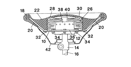
FIG. 1 is a front, or driver's side, view of a steering
wheel and airbag module in accordance with the present invention;
FIG. 2 is a cross-section taken substantially along the
line 2-2 of Fig. 1;
FIG. 3 is an enlarged partial cross-section illustrating
one way of retaining the airbag within the steering wheel;
FIG. 4 is a plan view of an airbag retainer ring usable
in the present invention; and
FIG. 5 is a view similar to FIG. 3 showing the manner of
installing the retainer ring of FIG. 3.

BEST MODE FOR CARRYING OUT THE l~v~.~ION

In accordance with the present invention, a hub plate 10
having a depressed central region 12 is mounted on a hub 14 which
is secured to the end of a steering column 16 by conventional
means. A steering wheel in the form of a rim armature 18 mounted
to one end of one or more spoke armatures 20 molded integrally into
a plastic body 22 provides an unbroken surface 24 as shown in FIG.

CA 022l0904 l997-07-2l


1. The body 22 is formed with an internal cavity 26. The front
surface of the body 22 overlying the cavity 26 is thinned on the
cavity side to form one or more tearlines 28, 30 which are designed
to burst open in a conventional manner to release the airbag upon
activation. The steering wheel is mounted to the hub plate 10 by
fastening means such as screws 32 which extend through the hub
plate 10 and into the spoke armatures 20. When so mounted, the
spoke armatures 20 extend radially outward from the hub plate and
the rim armature is located in a plane spaced from the hub plate 10
in a direction away from the steering column 16. Also releasably
secured on the hub plate 10 by means of nuts and bolts 34 is an
encircling mounting flange 36 of a conventional inflator 38. The
inflator 38 also extends downwardly into the depressed central
region 12 of the hub plate. The cavity 26 also encloses a folded
airbag 40. Thus it will be seen that the disclosed integral
steering wheel in and of itself becomes the airbag module.


- When the airbag or its inflator are to be serviced or
replaced, it is merely necessary to remove the screws 32 thereby
allowing the steering wheel to be removed and completely revealing
the airbag and inflator. A shroud 42 which is often present at the
back of the wheel may either be removed or provided with access
openings for reaching the screws 32.

As the airbag module of this invention does not have a
separate housing apart from the steering wheel itself, it is
possible to achieve a simplified construction in the manner of
installing the airbag. The airbag 40 has a conventional round
mouth 44 formed therein. The peripheral region surrounding this
mouth may be mounted between the mounting flange 36 of the inflator
and the hub plate lo. This is illustrated in the enlarged detail
view of FIG. 3. As will be seen therein, the fabric of the airbag
40 which surrounds the mouth 44 is positioned between the flange 36
of the inflator and the hub plate 10. In this position it is
pinched and retained by the nuts and bolts 34 which serve to
simultaneously mount the airbag and the inflator on the hub plate,
thus achieving an economy of parts and installation labor.

CA 02210904 1997-07-21


If it is deemed necessary to increase the friction
retaining the mouth of the airbag 40, a retainer ring 46 of the
type shown in FIG. 4 and disclosed and claimed in U.S. Patent No.
5,443,284 may be employed. The illustrated ring has four mounting
holes 48 for receiving the bolts 34 mounting the inflator 38 to the
hub plate 10. It is also pierced by eight U-shaped cuts about its
periphery. The material within each cut is bent downwardly to
create eight tabs 50 depending from eight U-shaped openings 52. As
illustrated in FIG. 5, the retaining ring is mounted atop the
fabric of the airbag 40 surrounding its mouth 44. Suitable
openings 54 are provided in the hub plate 10 to receive the tabs
after they have pierced the fabric. If desired, the tabs may be
longer and crimped below the hub plate for even more security. In
addition to increasing retention force on the airbag, the retainer
ring may be of a heat insulating material to help shield the airbag
fabric from the intense heat generated by some inflator gas
generants.

It is believed that the many advantages of this invention
will now be apparent to those skilled in the art. It will also be
apparent that a number of variations and modifications may be made
therein without departing from its spirit and scope. Accordingly,
the foregoing description is to be construed as illustrative only,
rather than limiting. This invention is limited only by the scope
of the following claims.

Representative Drawing
A single figure which represents the drawing illustrating the invention.
Administrative Status

For a clearer understanding of the status of the application/patent presented on this page, the site Disclaimer , as well as the definitions for Patent , Administrative Status , Maintenance Fee  and Payment History  should be consulted.

Administrative Status

Title Date
Forecasted Issue Date 1999-09-14
(22) Filed 1997-07-21
Examination Requested 1997-07-21
(41) Open to Public Inspection 1998-02-12
(45) Issued 1999-09-14
Deemed Expired 2006-07-21

Abandonment History

There is no abandonment history.

Payment History

Fee Type Anniversary Year Due Date Amount Paid Paid Date
Request for Examination $400.00 1997-07-21
Registration of a document - section 124 $100.00 1997-07-21
Application Fee $300.00 1997-07-21
Final Fee $300.00 1999-04-16
Maintenance Fee - Application - New Act 2 1999-07-21 $100.00 1999-07-07
Maintenance Fee - Patent - New Act 3 2000-07-21 $100.00 2000-06-14
Maintenance Fee - Patent - New Act 4 2001-07-23 $100.00 2001-06-27
Maintenance Fee - Patent - New Act 5 2002-07-22 $150.00 2002-06-25
Maintenance Fee - Patent - New Act 6 2003-07-21 $150.00 2003-07-03
Maintenance Fee - Patent - New Act 7 2004-07-21 $200.00 2004-07-02
Owners on Record

Note: Records showing the ownership history in alphabetical order.

Current Owners on Record
AUTOLIV ASP, INC.
Past Owners on Record
ADAMS, GARY VAIL
MANNINO, JOSEPH J.
RICKS, MERLE KAY
VIGEANT, PETER L.
Past Owners that do not appear in the "Owners on Record" listing will appear in other documentation within the application.
Documents

To view selected files, please enter reCAPTCHA code :


To view images, click a link in the Document Description column. To download the documents, select one or more checkboxes in the first column and then click the "Download Selected in PDF format (Zip Archive)" or the "Download Selected as Single PDF" button.

List of published and non-published patent-specific documents on the CPD .

If you have any difficulty accessing content, you can call the Client Service Centre at 1-866-997-1936 or send them an e-mail at CIPO Client Service Centre.


Document
Description 
Date
(yyyy-mm-dd) 
Number of pages   Size of Image (KB) 
Drawings 1997-07-21 2 40
Claims 1997-07-21 2 83
Description 1997-07-21 4 177
Representative Drawing 1998-03-03 1 14
Representative Drawing 1999-09-08 1 12
Abstract 1997-07-21 1 16
Cover Page 1999-09-08 1 48
Cover Page 1998-03-03 1 50
Correspondence 1997-09-30 1 33
Assignment 1997-07-21 3 118
Correspondence 1999-04-16 1 29
Assignment 1997-08-15 3 106
Assignment 1997-10-03 1 15
Assignment 1998-12-04 3 94
Correspondence 1998-12-21 1 2
Fees 1999-07-07 1 30