Note: Descriptions are shown in the official language in which they were submitted.
CA 02211117 1997-07-22
'WO 96/24989 PCTIUS96/01575
MULTI-POINT TO POINT COMMUNICATION SYSTEM
Field of the Invention
The present invention relates generally to the field of communication
systems. More particularly, the present invention relates to communication
systems with multicarrier telephony transport.
Backfzround of the Invention
Two information services found in households and businesses today
include television, or video, services and telephone services. Another
information service involves digital data transfer which is most frequently
accomplished using a modem connected to a telephone service. All further
references to telephony herein shall include both telephone services and
digital
data transfer services.
Characteristics of telephony and video signals are different and
therefore telephony and video networks are designed differently as well. For
example, telephony information occupies a relatively narrow band when
compared to the bandwidth for video signals. In addition, telephony signals
are low frequency whereas NTSC standard video signals are transmitted at
carrier frequencies greater than 50 MI-Iz. Accordingly, telephone transmission
networks are relatively narrow band systems which operate at audio
frequencies and which typically serve the customer by twisted wire drops from
a curb-side junction box. On the other hand, cable television services are
broad band and incorporate various frequency carrier mixing methods to
achieve signals compatible with conventional very high frequency television
receivers. Cable television systems or video services are typically provided
by
cable television companies through a shielded cable service connection to each
individual home or business.
One attempt to combine telephony and video services into a single
network is described in U.S. Patent No. 4,977,593 to Balance entitled "Optical
Communications Network." Balance describes a passive optical
CA 02211117 1997-07-22
WO 96/24989 PCTIUS96/01575
2
communications network with an optical source located in a central station.
The optical source transmits time division multiplexed optical signals along
an
optical fiber and which signals are later split by a series of splitters
between
several individual fibers servicing outstations. The network allows for
digital
speech data to be transmitted from the outstations to the central station via
the
same optical path. In addition, Balance indicates that additional wavelengths
could be utilized to add services, such as cable television, via digital
multiplex
to the network.
A 1988 NCTA technical paper, entitled "Fiber Backbone: A Proposal
For an Evolutionary Cable TV network Architecture," by James A. Chiddix
and David M. Pangrac, describes a hybrid optical fiber/coaxial cable
television
(CATV) system architecture. The architecture builds upon existing coaxial
CATV networks. The architecture includes the use of a direct optical fiber
path from a head end to a number of feed points in an already existing CATV
distribution system.
U.S. Patent No. 5,153,763 to Pidgeon, entitled "CATV Distribution
Networks Using Light Wave Transmission Lines," describes a CATV network
for distribution of broad band, multichannel CATV signals from a head end to
a plurality of subscribers. Electrical to optical transmitters at the head end
and optical to electrical receivers at a fiber node launch and receive optical
signals corresponding to broad band CATV electrical signals. Distribution
from the fiber node is obtained by transmitting electrical signals along
coaxial
cable transmission lines. The system reduces distortion of the transmitted
broad band CATV signals by block conversion of all or part of the broad band
of CATV signals to a frequency range which is less than an octave. Related
U.S. Patent No. 5,262,883 to Pidgeon, entitled "CATV Distribution Networks
Using Light Wave Transmission Lines," further describes the distortion
reducing system.
Although the above-mentioned networks describe various concepts for
transmitting broad band video signals over various architectures, which may
include hybrid optical fiber/coax architectures, none of these references
describe a cost effective, flexible, communications system for telephony
CA 02211117 1997-07-22
W O 96124989 PCT/US96/01575
3
communications. Several problems are inherent in such a communication
system.
One such problem is the need to optimize the bandwidth used for
k
transporting data so that the bandwidth used does not exceed the allotted
~
bandwidth. Bandwidth requirements are particularly critical in multi-point to
point communication where multiple transmitters at remote units must be
accommodated such that allotted bandwidth is not exceeded.
A second problem involves power consumption of the system. The
communication system should minimize the power used at the remote units for
the transport of data, as the equipment utilized at the remote units for
transmission and reception may be supplied by power distributed over the
transmission medium of the system.
Another problem arises from a fault in the system preventing
communication between a head end and multiple remote units of a multi-point
to point system. For example, a cut transmission line from a head end to
many remote units may leave many users without service. After the fault is
corrected, it is important bring as many remote units back into service as
quickly as possible.
Data integrity must also be addressed. Both internal and external
interference can degrade the communication. Internal interference exists
between data signals being transported over the system. That is, transported
data signals over a common communication link may experience interference
therebetween, decreasing the integrity of the data. Ingress from external
sources can also effect the integrity of data transmissions. A telephony
communication network is susceptible to "noise" generated by external
sources, such as HAM radio. Because such noise can be intermittent and vary
in intensity, a method of transporting data over the system should correct or
avoid the presence of such ingress.
These problems and others as will become apparent from the
description to follow, present a need for an enhanced communication system.
CA 02211117 1997-07-22
WO 96124989 PCT/US96/01575
4
Summary of the Invention
The present invention describes a multi-point to point communication
system including multicarrier telephony transport. The multi-point to point
communication system includes a hybrid fiber/coax distribution network. A
head end terminal provides for downstream transmission of downstream
control data and downstream telephony information in a first frequency
bandwidth over the hybrid fiber/coax distribution network and reception of
upstream telephony information and upstream control data in a second
frequency bandwidth over the hybrid fiber/coax distribution network. The
head end terminal includes a head end multicarrier modem for modulating at
least downstream telephony information on a plurality of orthogonal carriers
in the first frequency bandwidth and demodulating at least upstream telephony
information modulated on a plurality of orthogonal carriers in the second
frequency bandwidth. The head end terminal further includes a head end
controller operatively connected to the head end multicarrier modem for
controlling transmission of the downstream telephony information and
downstream control data and for controlling receipt of the upstream control
data and upstream telephony information. The system further includes at least
one service unit, each service unit associated with at least one remote unit
and
operatively connected to the hybrid fiber/coax distribution network for
upstream transmission of upstream telephony information and upstream control
data in the second frequency bandwidth and for receipt of the downstream
control data and downstream telephony information in the first frequency
bandwidth. Each service unit includes a service unit multicarrier modem for
modulating at least the upstream telephony information on at least one carrier
orthogonal at the head end to at least one other carrier in the second
frequency
bandwidth and for demodulating at least the downstream telephony
information modulated on at least a band of a plurality of orthogonal carriers
in the first frequency bandwidth. Each service unit also includes a service
unit controller operatively connected to the service unit multicarrier modem
for controlling the modulation of and demodulation performed by the service
unit multicarrier modem.
CA 02211117 1997-07-22
WO 96124989 PCT/US96/01575
In another embodiment, the plurality of orthogonal carriers in the first
frequency bandwidth include at least one control channel for transmission of
downstream control data and a plurality of telephony information channels for
transmission of downstream telephony information. Further, the plurality of
5 orthogonal carriers in the second frequency bandwidth include at least one
control channel for transmission of upstream control data and a plurality of
telephony information channels for transmission of upstream telephony
information.
In other embodiments, a plurality of control channels are interspersed
among the telephony information channels in the first frequency bandwidth
and a plurality of control channels are interspersed among the telephony
channels of the second frequency bandwidth.
In another embodiment, the at least one service unit includes a service
modem for upstream transmission of upstream telephony information and
upstream control data within a channel band of the second frequency
bandwidth corresponding to one of the channel bands of the first frequency
bandwidth in which the service modem receives downstream telephony
information and downstream control information. Alternatively, the at least
one service unit includes a multi-service modem for upstream transmission of
upstream telephony information and upstream control data within a plurality
of channel bands of the second frequency bandwidth corresponding to a
plurality of the channel bands of the first frequency bandwidth in which the
multi-service modem receives downstream telephony information and
downstream control information.
In still another embodiment, the plurality of control channels of the
first frequency bandwidth and the plurality of control channels of the second
frequency bandwidth each include at least one synchronization channel.
In other embodiments, different modulation techniques are utilized for
different carriers. For example, different modulation techniques are utilized
for different telephony channels.
A communication system which addresses the problems inherent in the
system, in particular, ingress problems is also described. The communication
CA 02211117 1997-07-22
WO 96/24989 PCT/US96/01575
6
system includes a distribution network between a head end terminal and at
least one remote unit. The head end terminal receives upstream telephony
information and upstream control data in a frequency bandwidth over the
distribution network. The head end terminal includes a head end multicarrier
demodulator for demodulating at least upstream telephony information
modulated on a plurality of orthogonal carriers in the frequency bandwidth.
The demodulator includes at least one polyphase filter for filtering the at
least
upstream telephony information modulated on the plurality of orthogonal
carriers to provide ingress protection for the modulated orthogonal carriers.
The head end terminal also includes a head end controller operatively
connected to the head end multicarrier demodulator for controlling receipt of
the upstream control data and upstream telephony information. The system
further includes at least one service unit modulator, each service unit
modulator associated with at least one remote unit and operatively connected
to the distribution network for modulating at least upstream telephony
information on at least one carrier orthogonal at the head end terminal to at
least one other carrier in the frequency bandwidth. The system also includes a
service unit controller operatively connected to the service unit multicarrier
modulator for controlling the modulation performed by the service unit
multicarrier modulator.
In another embodiment, the plurality of orthogonal carriers in the
frequency bandwidth include a plurality of telephony information channels for
transmission of upstream telephony information after modulation of telephony
information thereon and at least one control channel associated with the
plurality of telephony channels for transmission of upstream control data
thereon.
In another embodiment, the at least one polyphase filter includes a first
and second polyphase filter. The first polyphase filter filters a first
plurality
of channel sets and passes a first plurality of at least telephony channels
within each channel set of the first plurality of channel sets. The second ~=
polyphase filter filters a second plurality of channel sets and passes a
second plurality of at least telephony channels within each channel set of the
second
CA 02211117 1997-07-22
WO 96124989 PCT/US96101575
7
plurality of channel sets. The first and second polyphase filter are offset
from
one another such that all at least telephony channels of the first and second
plurality of channel sets are passed. In another embodiment, the polyphase
filters include at least two overlapping polyphase filters.
In another alternate embodiment, the demodulator includes a tunable
notch filter for filtering the at least upstream telephony information
modulated
on a plurality of orthogonal carriers to prevent passage of corrupted
modulated
orthogonal carriers.
In addition, a method of polyphase filtering in a communication system
is also described. The method includes receiving a plurality of orthogonal
carriers having modulated telephony information thereon. The plurality of
orthogonal carriers include a first and second plurality of noncontiguous
channel sets. The first plurality of noncontiguous channel sets are filtered
and
a first plurality of channels of each channel set of the first plurality of
noncontiguous channel sets are passed. The second plurality of noncontiguous '
channel sets are filtered and a second plurality of channels of each channel
set
of the second plurality of noncontiguous channel sets are also passed. The
second plurality of channels passed include channels of the first plurality of
noncontiguous channel sets not passed when filtering the first plurality of
noncontiguous channel sets.
A receiver apparatus is also described which receives a frequency
bandwidth having a plurality of modulated orthogonal carriers. At least one
polyphase filter provides ingress protection for the frequency bandwidth by
filtering a plurality of channel sets of the modulated orthogonal carriers.
A multi-point to point communication system utilizing a distributed
loop method is also described. The communication system in accordance with
the present invention includes a distribution network and a head end terminal
for downstream transmission of downstream control data and downstream
telephony information in a first frequency bandwidth over the distribution
network. The head end terminal receives upstream telephony information and
upstream control data in a second frequency bandwidth over the distribution
network. The head end terminal further includes a head end multicarrier
CA 02211117 1997-07-22
WO 96/24989 PCT/US96/01575
8
modem for modulating at least downstream telephony information on a
plurality of orthogonal carriers in the first frequency bandwidth and
demodulating at least upstream telephony information modulated on a plurality
of orthogonal carriers in the second frequency bandwidth. A head end
controller is operatively connected to the head end multicarrier modem for
controlling transmission of the downstream telephony information and
downstream control data and for controlling receipt of the upstream control
data and upstream telephony information. The system includes a plurality of
service units. Each service unit is associated with at least one remote unit
and
operatively connected to the distribution network for upstream transmission of
upstream telephony information and upstream control data in the second
frequency bandwidth and for receipt of the downstream control data and
downstream telephony information in the first frequency bandwidth. Each
service unit includes a service unit multicarrier modem for modulating at
least
the upstream telephony information on at least one carrier orthogonal to at
least one other carrier in the second frequency bandwidth and for
demodulating at least the downstream telephony information modulated on at
least a band of a plurality of orthogonal carriers in the first frequency
bandwidth. Each service unit also includes a service unit controller
operatively connected to the service unit multicarrier modem for controlling
the modulation of and demodulation performed by the service unit multicarrier
modem. The service unit controller adjusts at least one local transmission
characteristic in response to an adjustment command from the head end
controller transmitted in the downstream control data to the at least one
remote unit. The head end controller further includes a detector for detecting
the at least one local transmission characteristic of the service unit modem
associated with the at least one remote unit and for generating the adjustment
command as a function of the detected at least one transmission characteristic
for transmittal to the service unit associated with the at least one remote
unit
in the downstream control data.
Furthermore, communication system having a distribution network
between a head end and a plurality of remote units using a scanning method is
CA 02211117 1997-07-22
W O 96/24989 PCT/US96/01575
9
described. The system includes the transmission, from the head end, of a
plurality of modulated orthogonal carriers having telephony information
modulated thereon in a plurality of regions of a first frequency bandwidth.
Each of the regions has at least one control channel associated therewith
having control information modulated thereon. A scanner at the remote units,
scans each of the plurality of regions in the first frequency bandwidth and
locks onto the at least one control channel associated with each of the
plurality of regions to detect a unique identifier to determine which region
of
the first frequency bandwidth the remote unit is to tune to and which region
in
a second frequency bandwidth the remote unit is to transmit within.
In another embodiment, the communication system includes a
distribution network between a head end and a plurality of remote units. The
head end includes a head end terminal for downstream transmission of
downstream control data and downstream telephony information in a first
frequency bandwidth over the distribution network and for receipt of upstream
telephony information and upstream control data in a second frequency
bandwidth over the distribution network. The head end terminal includes a
head end multicarrier modem for modulating at least downstream telephony
information on a plurality of orthogonal carriers in a plurality of regions of
the first frequency bandwidth. The head end multicarrier modem also
demodulates at least upstream telephony information modulated on a plurality
of orthogonal carriers of a plurality of regions in the second frequency
bandwidth. The plurality of orthogonal carriers in each of the regions
includes a plurality of telephony information channels for transmission of
telephony information thereon with each of the regions having at least one
control channel associated therewith for transmission of control data. The
head end terminal also includes a head end controller operatively connected to
the head end multicarrier modem for controlling transmission of the
downstream telephony information and downstream control data and for
= 30 controlling receipt of the upstream control data and upstream telephony
information. The system further includes a plurality of service unit modems
with each service unit modem associated with at least one remote unit and
CA 02211117 1997-07-22
WO 96/24989 PCT/US96/01575
operatively connected to the distribution network for upstream transmission of
upstream telephony information and upstream control data in one of the
plurality of regions of the second frequency bandwidth and for receipt of the
downstream control data and downstream telephony information in one of the
5 plurality of regions in the first frequency bandwidth. Each service unit
modem includes a scanner for scanning each of the plurality of regions in the
first frequency bandwidth and for locking onto the at least one control
channel
in each of the plurality of regions to detect a unique identifier for each
service
unit modem to determine which region of the first frequency bandwidth the
10 service unit modem is to tune to and which region in the second frequency
bandwidth the service unit modem is to transmit within.
The present invention also describes a method of establishing
communication between a head end and a plurality of remote units in a multi-
point to point communication system, such as when a fault as described above
has left many users of the system without service. The method includes
transmitting information from the head end to the plurality of remote units in
a plurality of regions of a first frequency bandwidth. Each of the regions has
at least one control channel associated therewith. The information transmitted
includes identification information corresponding to each of n remote units of
the plurality of remote units. Such information is periodically transmitted
for
the n remote units from the head end on the at least one control channel of
one of the plurality of regions of the first frequency bandwidth during a
first
predetermined time period. The identification information for each of the
plurality of n remote units is transmitted out of phase with respect to the
identification information for the other of the n remote units. At each of the
n
remote units, the at least one control channel of each of the plurality of
regions in the first frequency bandwidth is scanned to detect identification
information corresponding to each of the n remote units to identify a
particular region of the plurality of regions that each of the n remote units
is
to use for receiving information from the head end. }
In one embodiment, a region is identified in a second frequency
bandwidth in which each of the n remote units is to transmit within. The
CA 02211117 1997-07-22
'WO 96124989 PCT/US96/01575
11
method further includes serially performing synchronization for each of the n
remote units for communication with the head end, during a second
predetermined time period after the first predetermined time period.
A multi-point to point communication system having a distribution
network between a head end and a plurality of remote units for accomplishing
the above method includes means for transmitting information from the head
end to the plurality of remote units in a plurality of regions of a first
frequency bandwidth. Each of the regions has at least one control channel
associated therewith. The transmitting means further periodically transmits
identification information corresponding to each of a set of n remote units of
the plurality of remote units on at least one control channel of one of the
plurality of regions of the first frequency bandwidth during a first
predetermined time period of an identification and synchronization time
period. The identification information for each of the plurality of n remote
units is transmitted out of phase with respect to the identification
information
for the other of the n remote units. The system further includes at each of
the
n remote units, means for scanning the at least one control channel of each of
the plurality of regions in the first frequency bandwidth to detect
identification
information during the first predetermined time period corresponding to each
of the n remote units to identify a particular region of the plurality of
regions
that each of the n remote units is to use for receiving information from the
head end. Further, at each of the n remote units, the system includes means
for modulating at least upstream telephony information on at least one carrier
in a second frequency bandwidth orthogonal at the head end terminal to at
least one other carrier in the second frequency bandwidth and for adjusting at
least one local transmission characteristic in response to an adjustment
command from the head end. Means at the head end for detecting the at least
one local transmission characteristic of each of the n remote units and for
generating the adjustment commands as a function of the detected at least one
transmission characteristic for transmittal to the n remote units to serially
-
perform synchronization for each of the n remote units during a second
CA 02211117 1997-07-22
WO 96/24989 PCT/US96/01575
12
predetermined time period of the identification and synchronization time
period is also included in the system.
The use of channel monitoring to address some of the problems
inherent in a multi-point to point communication system, in particular, with
respect to ingress, is also described. The monitoring method of the present
invention monitors a telephony communication n-bit channel wherein one of
the bits is a parity bit. The parity bit of the n-bit channel is sampled and a
probable bit error rate is derived from the sampling of the parity bit.
In one embodiment, the probable bit error rate over a time period is
compared to a predetermined bit error rate value representing a minimum bit
error rate to determine if the n-bit channel is corrupted. A corrupted channel
can then either be reallocated or, in another embodiment, the transmission
power of the channel can be increased to overcome the corruption.
In an alternate method embodiment, the method comprises the steps of
sampling the parity bit of the n-bit channel over a first time period,
deriving a
probable bit error rate from the sampling of the parity bit over the first
time
period, comparing the probable bit error rate over the first time period to a
pre-determined bit error rate value to determine if the n-bit channel is
corrupted, and accumulating a probable bit error rate over a plurality of
successive time periods if the n-bit channel is not corrupted.
In another alternate method embodiment, the method comprises the
steps of sampling the parity bit of the n-bit channel and deriving a probable
bit error rate from the sampling of the parity bit over a first time period.
The
probable bit error rate over the first time period is compared to a first
predetermined bit error rate value to determine if the n-bit channel is
corrupted. A probable bit error rate from the sampling of the parity bit over
a
second time period is derived. The second time period is longer than the first
time period and runs concurrently therewith. The probable bit error rate over
the second time period is compared to a second predetermined bit error rate
value to determine if the n-bit channel is corrupted.
In still yet another alternate embodiment, a method for monitoring at
least one unallocated telephony coniununication channel includes periodically
CA 02211117 1997-07-22
W U 96124989 PCT/US96/01575
13
monitoring the at least one unallocated telephony communication channel.
Error data for the at least one unallocated telephony communication channel
accumulated and the at least one unallocated telephony communication
channel is allocated based on the error data.
Brief Description of the Drawings
Figure 1 shows a block diagram of a communication system in
accordance with the present invention utilizing a hybrid fiber/coax
distribution
network;
Figure 2 is an alternate embodiment of the system of Figure 1;
Figure 3 is a detailed block diagram of a host digital terminal (HDT)
with associated transmitters and receivers of the system of Figure 1;
Figure 4 is a block diagram of the associated transmitters and receivers
of Figure 3;
Figure 5 is a block diagram of an optical distribution node of the
system of Figure 1;
Figure 6 is a general block diagram of an integrated service unit (ISU)
such as a home integrated service unit (HISU) or a multiple integrated service
unit (MISU) of Figure 1;
Figures 7A, 7B, 7C show data frame structures and frame signaling
utilized in the HDT of Figure 3;
Figure 8 is a general block diagram of a coax master card (CXMC) of
a coax master unit (CXMU) of Figure 3;
Figure 9A shows a spectral allocation for a first transport embodiment
for telephony transport in the system of Figure 1;
Figure 9B shows a mapping diagram for QAM modulation;
Figure 9C shows a mapping diagram for BPSK modulation;
Figure 9D shows a subband diagram for the spectral allocation of
Figure 9A;
Figure 9E shows a timing diagram of an identification and
synchronization process;
CA 02211117 1997-07-22
WO 96/24989 PCT/US96/01575
14
Figure 9F shows a timing diagram of a burst identification and
synchronization process;
Figure 10 is a block diagram of a master coax card (MCC)
downstream transmission architecture of the CXMU for the first transport
embodiment of the system of Figure 1;
Figure 11 is a block diagram of a coax transport unit (CXTU)
downstream receiver architecture of an MISU for the first transport
embodiment of the system of Figure 1;
Figure 12 is a block diagram of a coax home module (CXHM)
downstream receiver architecture of an HISU for the first transport
embodiment of the of the system of Figure 1;
Figure 13 is a block diagram of a CXHM upstream transmission
architecture associated with the CXHM downstream receiver architecture of
Figure 12;
Figure 14 is a block diagram of a CXTU upstream transmission
architecture associated with the CXTU downstream receiver architecture of
Figure 11;
Figure 15 is a block diagram of an MCC upstream receiver architecture
associated with the MCC downstream transmission architecture of Figure 10;
Figure 16 is a flow diagram of a acquisition distributed loop routine
for use with the system of Figure 1;
Figure 17 is a flow diagram of a tracking distributed loop architecture
routine for use with the system of Figure 1;
Figure 18 shows a magnitude response of a polyphase filter bank of
the MCC upstream receiver architecture of Figure 15;
Figure 19 is an enlarged view of part of the magnitude response of
Figure 18;
Figure 20 is a block diagram of a ingress filter structure and FFT of
the MCC upstream receiver architecture of Figure 15;
Figure 21 is a block diagram of a polyphase filter structure of the
ingress filter structure and FFT of Figure 20;
CA 02211117 1997-07-22
'WO 96124989 PCT/US96101575
Figure 22A is a block diagram of a carrier, amplitude, timing recovery
block of the downstream receiver architectures of the first transport
embodiment;
Figure 22B is a block diagram of a carrier, amplitude, timing recovery
5 block of the MCC upstream receiver architecture of the first transport
embodiment;
Figure 23 is a block diagram of internal equalizer operation for the
receiver architectures of the first transport embodiment;
Figure 24 is a spectral allocation of a second transport embodiment for
10 transport in the system of Figure 1;
Figure 25 is a block diagram of an MCC modem architecture of the
CXMU for the second transport embodiment of the system of Figure 1;
Figure 26 is a block diagram of a subscriber modem architecture of the
HISU for the second transport embodiment of the system of Figure 1;
15 Figure 27 is a block diagram of a modem of the subscriber modem
architecture of Figure 26;
Figure 28 is a block diagram for channel monitoring used in the
system of Figure 1;
Figures 29A, 29B, and 29C are flow diagrams for error monitor
portions of channel monitor routines of Figure 28;
Figure 29D is an alternate flow diagram for the diagram of Figure
29B;
Figure 30 is a flow diagram for a background monitor portion of the
channel monitor routines of Figure 28; and
Figure 31 is a flow diagram for a backup portion of the channel
monitor routines of Figure 28.
Detailed Description of the Preferred Embodiment
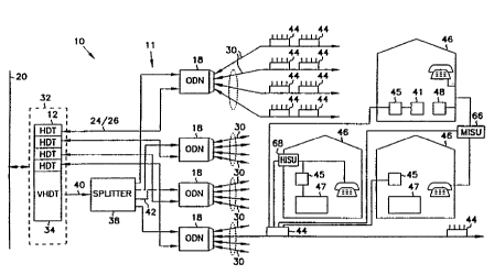
The communication system 10, as shown in Figure 1, of the present
invention is an access platform primarily designed to deliver residential and
business telecommunication services over a hybrid fiber-coaxial (HFC)
distribution network 11. The system 10 is a cost-effective platform for
delivery of telephony and video services. Telephony services may include
CA 02211117 1997-07-22
WO 96/24989 PCT/US96/01575
16
standard telephony, computer data and/or telemetry. In addition, the present
system is a flexible platform for accommodating existing and emerging
services for residential subscribers.
The hybrid fiber-coaxial distribution network 11 utilizes optical fiber
feeder lines to deliver telephony and video service to a distribution node 18
(referred to hereinafter as the optical distribution node (ODN)) remotely
located from a central office or a head end 32. From the ODNs 18, service is
distributed to subscribers via a coaxial network. Several advantages exist by
utilizing the HFC-based cominunication system 10. By utilizing fiber installed
in the feeder, the system 10 spreads the cost of optoelectronics across
hundreds of subscribers. Instead of having a separate copper loop which runs
from a distribution point to each subscriber ("star" distribution approach),
the
system 10 implements a bused approach where a distribution coaxial leg 30
passes each home and subscribers "tap" the distribution coaxial leg 30 for
service. The system 10 also allows non-video services to be modulated for
transmission using more cost-effective RF modem devices in dedicated
portions of the RF spectrum. Finally, the system 10 allows video services to
be carried on existing coaxial facilities with no additional subscriber
equipment because the coaxial distribution links can directly drive existing
cable-ready television sets.
It should be apparent to one skilled in the art that the modem transport
architecture described herein and the functionality of the architecture and
operations surrounding such architecture could be utilized with distribution
networks other than hybrid fiber coax networks. For example, the
functionality may be performed with respect to wireless systems. Therefore,
the present invention contemplates use of such systems in accordance with the
accompanying claims.
The system 10 includes host digital terminals 12 (HDTs) which
implement all common equipment functions for telephony transport, such as
network interface, synchronization, DSO grooming, and operations, ~=
administration, maintenance and provisioning (OAM&P) interfaces, and which
include the interface between the switching network and a transport system
CA 02211117 1997-07-22
'WO 96124989 PCT/US96101575
17
which carries information to and from customer interface equipment such as
integrated service units 100 (ISUs). Integrated services units (ISUs) 100,
such
as home integrated service units (HISUs) 68 or multiple user integrated
ti
service units (MISUs) 66, which may include a business integrated service
unit as opposed to a multiple dwelling integrated service unit, implement all
customer interface functions and interface to the transport system which
carries information to and from the switched network. In the present system,
the HDT 12 is normally located in a central office and the ISUs 100 are
remotely located in the field and distributed in various locations. The HDT
12 and ISUs 100 are connected via the hybrid fiber-coax distribution network
11 in a multi-point to point configuration. In the present system, the modem
functionality required to transport information over the HFC distribution
network 11 is performed by interface equipment in both the HDT 12 and the
ISUs 100. Such modem functionality is performed utilizing orthogonal
frequency division multiplexing.
The communication system shall now be generally described with
reference to Figures 1, 3 and 6. The primary components of system 10 are
host digital terminals (HDTs) 12, video host distribution terminal (VHDT) 34,
telephony downstream transmitter 14, telephony upstream receiver 16, the
hybrid fiber coax (HFC) distribution network 11 including optical distribution
node 18, and integrated service units 66, 68 (shown generally as ISU 100 in
Figure 6) associated with remote units 46. The HDT 12 provides telephony
interface between the switching network (noted generally by trunk line 20)
and the modem interface to the HFC distribution network for transport of
telephony information. The telephony downstream transmitter 14 performs
electrical to optical conversion of coaxial RF downstream telephony
information outputs 22 of an HDT 12, shown in Figure 3, and transmits onto
redundant downstream optical feeder lines 24. The telephony upstream
receiver 16 performs optical to electrical conversion of optical signals on
= 30 redundant upstream optical feeder lines 26 and applies electrical signals
on
coaxial RF upstream telephony information inputs 28 of HDT 12. The optical
distribution node (ODN) 18 provides interface between the optical feeder lines
CA 02211117 1997-07-22
WO 96/24989 PCTIUS96/01575
18
24 and 26 and coaxial distribution legs 30. The ODN 18 combines
downstream video and telephony onto coaxial distribution legs 30. The
integrated services units provide modem interface to the coaxial distribution
network and service interface to customers.
The HDT 12 and ISUs 100 implement the telephony transport system
modulator-demodulator (modem) functionality. The HDT 12 includes at least
one RF MCC modem 82, shown in Figure 3 and each ISU 100 includes an RF
ISU modem 101, shown in Figure 6. The MCC modems 82 and ISU modems
101 use a multi-carrier RF transmission technique to transport telephony
information, such as DSO+ channels, between the HDT 12 and ISUs 100. This
multi-carrier technique is based on orthogonal frequency division multiplexing
(OFDM) where a bandwidth of the system is divided up into multiple carriers,
each of which may represent an information channel. Multi-carrier
modulation can be viewed as a technique which takes time-division
multiplexed information data and transforms it to frequency-division
multiplexed data. The generation and modulation of data on multiple carriers
is accomplished digitally, using an orthogonal transformation on each data
channel. The receiver performs the inverse transformation on segments of the
sampled waveform to demodulate the data. The multiple carriers overlap
spectrally. However, as a consequence of the orthogonality of the
transformation, the data in each carrier can be demodulated with negligible
interference from the other carriers, thus reducing interference between data
signals transported. Multi-carrier transmission obtains efficient utilization
of
the transmission bandwidth, particularly necessary in the upstream
communication of a multi-point to point system. Multi-carrier modulation
also provides an efficient means to access multiple multiplexed data streams
and allows any portion of the band to be accessed to extract such multiplexed
information, provides superior noise immunity to impulse noise as a
consequence of having relatively long symbol times, and also provides an
effective means for eliminating narrowband interference by identifying
carriers
which are degraded and inhibiting the use of these carriers for data
transmission (such channel monitoring and protection is described in detail
CA 02211117 1997-07-22
WO 96/24989 PCTIUS96/01575
19
below). Essentially, the telephony transport system can disable use of
carriers
which have interference and poor performance and only use carriers which
meet transmission quality targets.
Further, the ODNs 18 combine downstream video with the telephony
information for transmission onto coaxial distribution legs 30. The video
information from existing video services, generally shown by trunk line 20, is
received by and processed by head end 32. Head end 32 or the central office,
includes a video host distribution terminal 34 (VHDT) for video data
interface. The VHDT 34 has optical transmitters associated therewith for
communicating the video information to the remote units 46 via the ODNs 18
of the distribution network 11.
The telephony transmitter 14 of the HDTs 12, shown in Figure 3 and
4, includes two transmitters for downstream telephony transmission to protect
the telephony data transmitted. These transmitters are conventional and
relatively inexpensive narrow band laser transmitters. One transmitter is in
standby if the other is functioning properly. Upon detection of a fault in the
operating transmitter, the transmission is switched to the standby
transmitter.
In contrast, the transmitter of the VHDT 34 is relatively expensive as
compared to the transmitters of HDT 12 as it is a broad band analog DFB
laser transmitter. Therefore, protection of the video information, a non-
essential service unlike telephony data, is left unprotected. By splitting the
telephony data transmission from the video data transmission, protection for
the telephony data alone can be achieved. If the video data information and
the telephony data were transmitted over one optical fiber line by an
expensive broad band analog laser, economies may dictate that protection for
telephony services may not be possible. Therefore, separation of such
transmission is of importance.
Further with reference to Figure 1, the video information is optically
transmitted downstream via optical fiber line 40 to splitter 38 which splits
the
optical video signals for transmission on a plurality of optical fiber lines
42 to
a plurality of optical distribution nodes 18. The telephony transmitter 14
associated with the HDT 12 transmits optical telephony signals via optical
CA 02211117 1997-07-22
WO 96/24989 PCT/US96/01575
fiber feeder line 42 to the optical distribution nodes 18. The optical
distribution nodes 18 convert the optical video signals and optical telephony
signals for transmission as electrical outputs via the coaxial distribution
portion of the hybrid fiber coax (HFC) distribution network 11 to a plurality
5 of remote units 46. The electrical downstream video and telephony signals
are distributed to ISUs via a plurality of coaxial legs 30 and coaxial taps 44
of
the coaxial distribution portion of the HFC network 11.
The remote units 46 have associated therewith an ISU 100, shown
generally in Figure 6, that includes means for transmitting upstream
electrical
10 data signals including telephony information, such as from telephones and
data
terminals, and in addition may include means for transmitting set top box
information from set top boxes 45 as described further below. The upstream
electrical data signals are provided by a plurality of ISUs 100 to an optical
distribution node 18 connected thereto via the coaxial portion of the HFC
15 distribution network 11. The optical distribution node 18 converts the
upstream electrical data signals to an upstream optical data signal for
transmission over an optical fiber feeder line 26 to the head end 32.
Figure 2 generally shows an alternate embodiment for providing
transmission of optical video and optical telephony signals to the optical
20 distribution nodes 18 from head end 32, the HDT 12 and VHDT 34 in this
embodiment utilize the same optical transmitter and the same optical fiber
feeder line 36. The signals from HDT 12 and VHDT 34 are combined and
transmitted optically from headend 32 to splitter 38. The combined signal is
then split by splitter 38 and four split signals are provided to the optical
distribution nodes 18 for distribution to the remote units by the coaxial
distribution legs 30 and coaxial taps 44. Return optical telephony signals
from the ODNs 18 would be combined at splitter 38 for provision to the
headend. However, as described above, the optical transmitter utilized would
be relatively expensive due to its broad band capabilities, lessening the
probabilities of being able to afford protection for essential telephony
services.
As one skilled in the art will recognize, the fiber feeder lines 24, 26, as
shown in Figure 1, may include four fibers, two for transmission downstream
CA 02211117 1997-07-22
'WO 96124989 PCTIUS96/01575
21
from downstream telephony transmitter 14 and two for transmission upstream
to upstream telephony receiver 16. With the use of directional couplers, the
number of such fibers may be cut in half. In addition, the number of
protection transmitters and fibers utilized may vary as known to one skilled
in
ti
the art and any listed number is not limiting to the present invention as
described in the accompanying claims.
The present invention shall now be described in further detail. The
first part of the description shall primarily deal with video transport. The
remainder of the description shall primarily be with regard to telephony
transport.
VIDEO TRANSPORT
The communication system 10 includes the head end 32 which receives
video and telephony information from video and telephony service providers
via trunk line 20. Head end 32 includes a plurality of HDTs 12 and a VHDT
34. The HDT 12 includes a network interface for communicating telephony
information, such as Ti, ISDN, or other data services information, to and
from telephony service providers, such communication also shown generally
by trunk line 20. The VHDT 34 includes a video network interface for
communicating video information, such as cable TV video information and
interactive data of subscribers to and from video service providers, such
communication also shown generally by trunk line 20.
The VHDT 34 transmits downstream optical signals to a splitter 38 via
video optical fiber feeder line 40. The passive optical splitter 38
effectively
makes four copies of the downstream high bandwidth optical video signals.
The duplicated downstream optical video signals are distributed to the
correspondingly connected optical distribution nodes 18. One skilled in the
art will readily recognize that although four copies of the downstream video
signals are created, any number of copies may be made by an appropriate
splitter and that the present invention is not limited to any specific number.
The splitter is a passive means for splitting broad band optical signals
without the need to employ expensive broad band optical to electrical
CA 02211117 1997-07-22
WO 96/24989 PCT/US96/01575
22
conversion hardware. Optical signal splitters are commonly known to one
skilled in the art and available from numerous fiber optic component
manufacturers such as Gould, Inc. In the alternative, active splitters may
also
be utilized. In addition, a cascaded chain of passive or active splitters
would
further multiply the number of duplicated optical signals for application to
an
additional number of optical distribution nodes and therefore increase further
the remote units serviceable by a single head end. Such alternatives are
contemplated in accordance with the present invention as described by the
accompanying claims.
The VHDT 34 can be located in a central office, cable TV head end,
or a remote site and broadcast up to about 112 NTSC channels. The VHDT
34 includes a transmission system like that of a LiteAMpTM system available
from American Lightwave Systems, Inc., currently a subsidiary of the assignee
hereof. Video signals are transmitted optically by amplitude modulation of a
1300 nanometer laser source at the same frequency at which the signals are
received (i.e. the optical transmission is a terahertz optical carrier which
is
modulated with the RF video signals). The downstream video transmission
bandwidth is about 54-725 MHz. One advantage in using the same frequency
for optical transmission of the video signal as the frequency of the video
signals when received is to provide high bandwidth transmission with reduced
conversion expense. This same-frequency transmission approach means that
the modulation downstream requires optical to electrical conversion or
proportional conversion with a photodiode and perhaps amplification, but no
frequency conversion. In addition, there is no sample data bandwidth
reduction and little loss of resolution.
An optical distribution node 18, shown in further detail in Figure 5,
receives the split downstream optical video signal from the splitter 38 on
optical fiber feeder line 42. The downstream optical video signal is applied
to
a downstream video receiver 400 of the optical distribution node 18. The
optical video receiver 400 utilized is like that available in the Lite AMpT"
product line available from American Lightwave Systems, Inc. The converted
signal from video receiver 400, proportionally converted utilizing
photodiodes,
CA 02211117 1997-07-22
WO 96124989 PCTYUS96/01575
23
is applied to bridger amplifier 403 along with converted telephony signals
from downstream telephony receiver 402. The bridger amplifier 403
simultaneously applies four downstrcam electrical telephony and video signals
ti
to diplex filters 406 which allow for full duplex operation by separating the
~
transmit and receive functions when signals of two different frequency
bandwidths are utilized for upstream and downstream transmission. There is
no frequency conversion performed at the ODN 18 with respect to the video
or the downstream telephony signals as the signals are passed through the
ODNs to the remote units via the coaxial portion of the HFC distribution
network 11 in the same frequency bandwidth as they are received at the
ODNs 18.
After the ODN 18 has received the downstream optical video signals
and such signals are converted to downstream electrical video signals, the
four
outputs of the ODN 18 are applied to four coaxial legs 30 of the coaxial
portion of the HFC distribution network 11 for transmission of the
downstream electrical video signals to the remote units 46. Such transmission
for the electrical video signals occurs in about the 54-725 MHz bandwidth.
Each ODN 18 provides for the transmission on a plurality of coaxial legs 30
and any number of outputs is contemplated in accordance with the present
invention as described in the accompanying claims.
As shown in Figure 1, each coaxial cable leg 30 can provide a
significant number of remote units 46 with downstream electrical video and
telephony signals through a plurality of coaxial taps 44. Coaxial taps are
commonly known to one skilled in the art and act as passive bidirectional
pickoffs of electrical signals. Each coaxial cable leg 30 may have a number
of coaxial taps 44 connected in series. In addition, the coaxial portion of
the
HFC distribution network 11 may use any number of amplifiers to extend the
distance data can be sent over the coaxial portion of such distribution
network
11.
Downstream video signals are provided from the coaxial taps 44 to the
remote units 46. The video signal from the coaxial tap 44 is provided to an
HISU 68 which is generally shown by the block diagram of ISU 100 in
CA 02211117 1997-07-22
WO 96/24989 PCT/US96/01575
24
Figure 6. The ISU 100 is provided with the downstream electrical video and
telephony signal from tap 44 and it is applied to diplex filter 104. The
downstream electrical video and telephony signal is passed through the diplex
filter 104 to both an ingress filter 105 and ISU modem 101. The downstream
video signal is passed by the ingress filter 105 to video equipment via an
optional set top box 45. The downstream electrical telephony signal applied
from the diplex filter 104 to the ISU modem 101 is processed as described in
further detail below.
Ingress filter 105 provides the remote unit 46 with protection against
interference of signals applied to the video equipment as opposed to those
provided to other user equipment such as telephones or computer terminals.
Ingress filter 105 passes the video signals; however, it blocks those
frequencies not utilized by the video equipment. By blocking those
frequencies not used by the video equipment, stray signals are eliminated that
may interfere with the other services by the network to at least the same
remote unit.
The set top box 45 is an optional element at the remote unit 46.
Interactive video data from set top box 45 would be transmitted by an
additional separate RF modem provided by the video service provider at a
relatively low frequency in the bandwidth of about 5 to 40 MHz. Such
frequency must not be one used for the transport of upstream and downstream
telephony data and downstream video.
For an MISU 66, a separate coaxial line from coaxial tap 44 is
utilized to provide transmission of video signals from the coaxial tap 44 to
the
set top box 45 and thus for providing downstream video signals to video
equipment 47. The ingress filter 105 as shown in Figure 6 is not a part of the
MISU 66 as indicated by its dashed representation.
Alternative embodiments of the VHDT 34 may employ other
modulation and mixing schemes or techniques to shift the video signals in
frequency, and other encoding methods to transmit the information in a coded
format. Such techniques and schemes for transmitting analog video data, in
addition to those transmitting digital video data, are known to one skilled in
CA 02211117 1997-07-22
WO 96124989 PCT/US96/01575
the art and are contemplated in accordance with the spirit and scope of the
present invention as described in the accompanying claims.
TELEPHONY TRANSPORT
5 With reference to Figure 3, telephony information and ISU operations
and control data (hereinafter referred to as control data) modulated on
carriers
by MCC modem 82 is transmitted between the HDT 12 and the telephony
downstream transmitter 14 via coaxial lines 22. Telephony information and
control data modulated on carriers by ISUs 100 is received at telephony
10 upstream receiver 16 and communicated to the MCC modem 82 via coaxial
cable lines 28. The telephony downstream transmitter 14 and the telephony
upstream receiver 16 transmit and receive, respectively, telephony information
and control data via optical fiber feeder lines 24 and 26 to and from a
corresponding optical distribution node 18. The control data may include all
15 operations, administration, maintenance & provisioning (OAM&P) for
providing the telephony services of the system 11 and any other control data
necessary for providing transport of telephony information between the HDT
12 and the ISUs 100.
A block diagram of the HDT 12 is shown in Figure 3. The HDT 12
20 includes the following modules: Eight DS 1 Units (DS 1 U) (seven quad-DS 1
units 48 plus one protection unit 50), one protection switch & test conversion
unit 52 (PSTU), two clock & time slot interchange units 54 (CTSUs) (one
active and one standby/protection unit), six coax master units 56 (CXMUs)
(three active and three standby/protection units), two shelf control units 58
25 (SCNUs) (one active and one standby/protection unit), and two power supply
units 60 (PWRUs) (two load-sharing units which provide the appropriate HDT
voltages from a central office supply).
The HDT 12 comprises all the common equipment functions of the
telephony transport of the communication system 10. The HDT 12 is
= 30 normally located in a central office and directly interfaces to a local
digital
switch or digital network element equipment. The HDT provides the network
interface 62 for all telephony information. Each HDT accommodates from 2
CA 02211117 1997-07-22
WO 96/24989 PCT/US96/01575
26
to 28 DSX-1 inputs at the network interface 62, representing a maximum of
672 DSO channels.
The HDT 12 also provides all synchronization for telephony transport
in the system 11. The HDT 12 may operate in any one of three
synchronization modes: external timing, line timing or internal timing.
External timing refers to synchronization to a building integrated timing
supply reference which is sourced from a central office in which the HDT 12
is located. Line timing is synchronized to the recovered clock from a DSX-1
signal normally derived from the local digital switch. Internal timing is a
free-running or hold-over operation where the HDT maintains its own
synchronization in the absence of any valid reference inputs.
The HDT 12 also provides quarter-DSO grooming capabilities and
implements a 4096 x 4096 full-access, non-blocking quarter-DSO (16 kbps)
cross-connect capability. This allows DSOs and quarter-DSOs (ISDN "D"
channels) to be routed from any timeslot at the DSX-1 network interface 62 to
any customer serviced by any ISU 100.
The HDT 12 further provides the RF modem functionality required for
telephony transport over the HFC distribution network 11 including the MCC
modem 82. The HDT 12 accommodates up to three active CXMUs 56 for
providing the modem interface to the HFC distribution network 11 and also
provides one-for-one protection for each active CXMU 56.
The HDT 12 coordinates the telephony transport system including
control and communication of many ISUs of the multi-point to point
communication system 11. Each HDT 12 module performs a function. The
DS1U module 48 provides the interface to the digital network and DSX-1
termination. The PSTU 52 provides DS1U equipment protection by switching
the protection DS1U 50 for a failed DS1U module 48. The CTSU 54
provides the quarter-DSO timeslot grooming capability and all system
synchronization functions. The CTSU 54 also coordinates all call processing in
the system. The CXMU 56, described in further detail below, provides the
modem functionality and interface for the OFDM telephony transport over the
HFC distribution network 11 and the SCNU 58 supervises the operation of the
CA 02211117 1997-07-22
WO 96124989 PCTI7JS96103575
27
entire communication system providing all OAM&P functions for telephony
transport. Most processing of requests for provisioning is performed by the
SCNU 58.
Downstream Telephony Transmitter
The downstream telephony transmitter 14, shown in Figure 4, takes the
coaxial RF outputs 22 from the active CXIVILJs 56 of the HDT 12 which carry
telephony information and control data and combines the outputs 22 into a
downstream telephony transmission signal. The electrical-to-optical
conversion logic required for the optical transmission is implemented in a
stand-alone downstream telephony transmitter 14 rather than in the HDT 12 to
provide a more cost effective transport solution. By placing this function in
a
separate component, the expense of this function does not need to be
replicated in each CXMU 56 of the HDT 12. This reduces the cost of the
CXMU 56 function and allows the CXMU 56 to transmit and receive over
coax instead of fiber. The downstream telephony transmitter 14 also provides
for transmission on redundant downstream fiber feeder lines 24 to an ODN
18.
The downstream telephony transmitter 14 is co-located with the HDT
12 preferably within a distance of 100 feet or less. The downstream
telephony transmitter 14 receives the coaxial RF outputs from the active
CXMUs 56, each within a 6 MHz frequency band, and combines them at
combiner 25 into a single RF signal. Each 6 MHz frequency band is
separated by a guard band as is known to one skilled in the art. Downstream
telephony information is then transmitted in about the 725-800 MHz frequency
band. The telephony transmitter 14 passes the combined signal through a 1-
to-2 splitter (not shown), thereby producing redundant downstream electrical
signals. The two redundant signals are each delivered to redundant laser
transmitters 501 for electricaI-to-optical conversion and the redundant
signals
modulate an optical output such that the output of the downstream telephony
transmitter 14 is on two optical feeder lines 24, each having an identical
signal modulated thereon. This provides protection for the downstream
CA 02211117 1997-07-22
WO 96/24989 PCT/US96/01575
28
telephony portion of the present system. Both Fabry-Perot lasers in the
telephony transmitter 14 are active at all times. All protection functions are
provided at the receive end of the optical transmission (located at the ODN
18) where one of two receivers is selected as "active;" therefore, the
telephony
transmitter 14 requires no protection switching capabilities.
Upstream Telephony Receiver
The upstream telephony receiver 16 performs the optical-to-electrical
conversion on the upstream optical telephony signals on the upstream optical
feeder lines 26 from the ODN 18. The upstream telephony receiver 16 is
normally co-located in the central office with the HDT 12, and provides an
electrical coaxial output to the HDT 12, and a coaxial output 23 to be
provided to a video set-top controller (not shown). Upstream telephony
information is routed via coax lines 28 from the upstream telephony receiver
16 to active CXMUs 56 of the HDT 12. The coaxial link 28 between the
HDT 12 and the upstream telephony receiver 16 is preferably limited to a
distance of 100 feet or less and is an intra-office link. Video set-top
controller information, as described in the Video Transport section hereof, is
located in a bandwidth of the RF spectrum of 5-40 MHz which is not utilized
for upstream telephony transport such that it is transmitted along with the
upstream telephony information.
The upstream telephony receiver 16 has dual receivers 502 for the dual
upstream optical fiber feeders lines 26. These feeder lines 26 carry redundant
signals from the ODN 18 which contain both telephony information and
control data and also video set-top box information. The upstream telephony
receiver 16 performs automatic protection switching on the upstream feeder
lines 26 from the ODN. The receiver 502 selected as "active" by protection
logic is split to feed the coaxial outputs 28 which drive the HDT 12 and
output 23 is provided to the set-top controller (not shown).
Optical Distribution Node
CA 02211117 1997-07-22
WO 96/24989 PCT/US96/01575
29
Referring to Figure 5, the ODN 18 provides the interface between the
optical feeder lines 24 and 26 from the HDT 12 and the coaxial portion of the
HFC distribution network 11 to the remote units 46. As such, the ODN 18 is
essentially an optical-to-electrical and electrical-to-optical converter. The
maximum distance over coax of any ISU 100 from an ODN 18 is preferably
about 6 km and the maximum length of the combined optical feeder
line/coaxial drop is preferably about 20 km. The optical feeder line side of
the ODN 18 terminates six fibers although such number may vary. They
include: a downstream video feeder line 42 (single fiber from video splitter
38), a downstream telephony feeder line 24 (from downstream telephony
transmitter 14), a downstream telephony protection feeder line 24 (from
downstream telephony transmitter 14), an upstream telephony feeder line 26
(to upstream telephony receiver 16), an upstream protection feeder line 26 (to
upstream telephony receiver 16), and a spare fiber (not shown). The ODN 18
provides protection switching functionality on the receive optical feeder
lines
24 from the downstream telephony transmitter. The ODN provides redundant
transmission on the upstream optical feeder lines 26 to the upstream telephony
receiver. Protection on the upstream optical feeder lines is controlled at the
upstream telephony receiver 16. On the coaxial distribution side of ODN 18,
the ODN 18 terminates up to four coaxial legs 30.
In the downstream direction, the ODN 18 includes downstream
telephony receiver 402 for converting the optical downstream telephony signal
into an electrical signal and a bridger amplifier 403 that combines it with
the
converted downstream video signal from downstream video receiver 400
terminated at the ODN 18 from the VHDT 34. This combined wide-band
electrical telephony/video signal is then transported in the spectrum
allocated
for downstream transmission, for example, the 725-800 MHz band, on each of
the four coaxial legs of the coaxial portion of the HFC distribution network
11. As such, this electrical telephony and video signal is carried over the
coaxial legs 30 to the ISUs 100; the bridger amplifier 403 simultaneously
applying four downstream electrical telephony and video signals to diplex
filters 406. The diplex filters 406 allow for full duplex operation by
CA 02211117 1997-07-22
WO 96/24989 PCT/US96/01575
separating the transmit and receive functions when signals at two different
frequency bandwidths are utilized for upstream and downstream transmission.
There is no frequency conversion available at the ODN 18 for downstream
transport as the telephony and video signals are passed through the ODN 18 to
5 the remote units 46 via the coaxial portion of HFC distribution network 11
in
the same frequency bandwidth as they are received at the ODN 18. As shown
in Figure 1, each coaxial leg 30 can provide a significant number of remote
units 46 with downstream electrical video and telephony signals through a
plurality of coaxial taps 44. Coaxial taps 44 commonly known to one skilled
10 in the art act as passive bidirectional pickoffs of electrical signals.
Each
coaxial leg 30 may have a number of coaxial taps connected in a series. In
addition, the coaxial portion of the HFC distribution network 11 may use any
number of amplifiers to extend the distance data can be sent over the coaxial
portions of the system 10. The downstream electrical video and telephony
15 signals are then provided to an ISU 100 (Figure 6), which, more
specifically,
may be an HISU 68 or an MISU 66 as shown in Figure 1.
In the upstream direction, telephony and set top box information is
received by the ODN 18 at diplex filters 406 over the four coaxial legs 30 in
the RF spectrum region from 5 to 40 MHz. The ODN 18 may include
20 optional frequency shifters 64 equipped on up to three of four coaxial legs
30.
These frequency shifters 64, if utilized, mix the upstream spectrum on a
coaxial leg to a higher frequency prior to combining with the other three
coaxial legs. Frequency shifters 64 are designed to shift the upstream
spectrum in multiples of 50 MHz. For example, the frequency shifters 64
25 may be provisioned to mix the upstream information in the 5-40 MHz portion
of the RF spectrum to any of the following ranges: 50 to 100 MHz, 100 to
150 MHz, or 150 to 200 MHz. This allows any coaxial leg 30 to use the
same portion of the upstream RF spectrum as another leg without any
spectrum contention when the upstream information is combined at the ODN
30 18. Provisioning of frequency shifters is optional on a coaxial leg 30. The
ODN 18 includes combiner 408 which combines the electrical upstream
telephony and set top box information from all the coaxial legs 30 (which
CA 02211117 1997-07-22
1iVO 96124989 PCT/i7S96/01575
31
may or may not be frequency shifted) to form one composite upstream signal
having all upstream information present on each of the four coaxial legs 30.
The composite electrical upstream signal is passively 1:2 split and each
signal
feeds an upstream Fabry-Perot laser transmitter which drives a corresponding
upstream fiber feeder line 26 for transmission to the upstream telephony
receiver 16.
If the upstream telephony and set top box signals are upshifted at the
ODN 18, the upstream telephony receiver 16 includes frequency shifters 31 to
downshift the signals according to the upshifting done at the ODN 18. A
combiner 33 then combines the downshifted signals for application of a
combined signal to the HDT 12. Such downshifting and combining is only
utilized if the signals are upshifted at the ODN 18.
Integrated Services Unit (ISUs)
Referring to Figure 1, the ISUs 100, such as HISU 68 and MISU 66,
provide the interface between the HFC distribution network 11 and the
customer services for remote units 46. Two basic types of ISUs are shown,
which provide service to specific customers. Multiple user integrated service
unit 66 (MISUs) may be a multiple dwelling integrated service unit or a
business integrated service unit. The multiple dwelling integrated service
unit
may be used for mixed residential and business environments, such as multi-
tenant buildings, small businesses and clusters of homes. These customers
require services such as plain old telephone service (POTS), d'ata services,
DS 1 services, and standard TR-57 services. Business integrated service units
are designed to service business environments. They may require more
services, for example, data services, ISDN, DS 1 services, higher bandwidth
services, such as video conferencing, etc. Home integrated services units 68
(HISUs) are used for residential environments such as single-tenant buildings
and duplexes, where the intended services are POTS and basic rate integrated
digital services network (ISDN). Description for ISUs shall be limited to the
HISUs and MISUs for simplicity purposes as multiple dwelling and business
l
CA 02211117 1997-07-22
WO 96/24989 PCT/US96/01575
32
integrated service units have similar functionality as far as the present
invention is concerned.
All ISUs 100 implement RF modem functionality and can be
generically shown by ISU 100 of Figure 6. ISU 100 includes ISU modem
101, coax slave controller unit (CXSU) 102, channel units 103 for providing
customer service interface, and diplex filter/tap 104. In the downstream
direction, the electrical downstream telephony and video signal is applied to
diplex filter/tap 104 which passes telephony information to ISU modem 101
and video information to video equipment via an ingress filter 105 in the case
of a HISU. When the ISU 100 is a MISU 66, the video information is
rejected by the diplex filter. The ISU modem 101 demodulates the
downstream telephony information utilizing a modem corresponding to the
MCC modem 82 used for modulating such information on orthogonal
multicarriers at HDT 12. ISU 100 demodulates downstream telephony
information from a coaxial distribution leg 30 in a provisionable 6 MHz
frequency band. Timing generation 107 of the ISU modem 101 provides
clocking for CXSU 102 which provides processing and controls reception and
transmission by ISU modem 101. The demodulated data from ISU modem
101 is passed to the applicable channel units 103 via CXSU 102 depending
upon the service provided. For example, the channel units 103 may include
line cards for POTS, DS1 services, ISDN, other data services, etc. Each ISU
100 provides access to a fixed subset of all channels available in a 6 MHz
frequency band corresponding to one of the CXMUs of HDT 12. This subset
of channels varies depending upon the type of ISU 100. An MISU 66 may
provide access to many DSO channels in a 6 MHz frequency band, while an
HISU 68 may only provide access to a few DSO channels.
The channel units 103 provide telephony information and control data
to the CXSU 102, which provides such data to ISU modem 101 and controls
ISU modem 101 for modulation of such telephony data and control data in a
provisional 6 MHz frequency band for transmission onto the coaxial
distribution leg 30 connected thereto. The upstream 6 MHz frequency band
provisionable for transmission by the ISU 100 to the HDT 12 corresponds to
CA 02211117 1997-07-22
WO 96/24989 PCT/1JS96/01575
33
one of the downstream 6 MHz bands utilized for transmission by the CXMUs
56 of HDT 12.
Each ISU 100 recovers synchronization from downstream transmission,
generates all clocks required for ISU data transport and locks these clocks to
the associated HDT timing. The ISUs 100 also provide call processing
functionality necessary to detect customer line seizure and line idle
conditions
and transmit these indications to the HDT 12. ISUs 100 terminate and receive
control data from the HDT 12 and process the control data received therefrom.
Included in this processing are messages to coordinate dynamic channel
allocation in the communication system 10. Finally, ISUs 100 generate ISU
operating voltages from a power signal received over the HFC distribution
network 11 as shown by the power signal 109 taken from diplex filter/tap 104.
Data Path in HDT
The following is a detailed discussion of the data path in the host
digital terminal (HDT) 12. Referring to Figure 3, the data path between the
network facility at the network interface 62 and the downstream telephony
transmitter 14 proceeds through the DS1U 48, CTSU 54, and CXMU 56
modules of the HDT 12, respectively, in the downstream direction. Each
DS 1 U 48 in the HDT 12 takes four DS 1 s from the network and formats this
information into four 24-channel, 2.56 Mbps data streams of modified DSO
signals referred to as CTSU inputs 76. Each DSO in the CTSU input has been
modified by appending a ninth bit which can carry multiframe timing,
signaling information and control/status messages (Figure 7A). This modified
DSO is referred to as a "DSO+." The ninth bit signal (NBS) carries a pattern
which is updated each frame and repeats every 24 frames. This maps each 64
kbps DSO from the network into a 72 kbps DSO+. Thus, the twenty-four DSO
channels available on each DS 1 are formatted along with overhead
information into twenty-four DSO+ channels on each of four CTSU input
streams.
The ninth bit signaling (NBS) is a mechanism developed to carry the
multiframe timing, out-of-band signaling bits and miscellaneous status and
I
CA 02211117 1997-07-22
WO 96124989 PCT/US96101575
34
control information associated with each DSO between the DS1U and the
channel units. Its main functions are to carry the signaling bits to channel
units 103 and to provide a multiframe clock to the channel units 103 so that
they can insert upstream bit signaling into the DSO in the correct frame of
the
multiframe. Because downstream DSOs may be coming from DS 1 s which do
not share the same multiframe phase each DSO must carry a multiframe clock
or marker which indicates the signaling frames associated with the origination
DS 1. The NBS provides this capability. Ninth bit signaling is transparent to
the OFDM modem transport of the communication system 11.
Up to eight DS1Us 48 may be equipped in a single HDT 12; including
seven active DS1Us 48 and a protection DS1U module 50. Thus, 32 CTSU
inputs are connected between the DS 1 Us and the CTSUs 54 but a maximum
of 28 can be enabled to carry traffic at any one time. The four remaining
CTSU inputs are from either the protection DS 1 U or a failed DS 1 U. The
PSTU includes switch control for switching the protection DS 1 U 50 for a
failed DS1U.
Each CTSU input is capable of carrying up to 32, 10-bit channels, the
first 24 channels carry DSO+s and the remaining bandwidth is unused. Each
CTSU input 76 is clocked at 2.56 Mbps and is synchronized to the 8 kHz
internal frame signal (Figure 7C). This corresponds to 320 bits per 125 sec
frame period. These 320 bits are framed as shown in Figure 7A. The
fourteen gap bits 72 at the beginning of the frame carry only a single
activity
pulse in the 2nd bit position, the remaining 13 bits are not used. Of the
following 288 bits, the first 216 bits normally carry twenty-four DSO+
channels where each DSO+ corresponds to a standard 64 kbps DSO channel
plus the additional 8 kbps signaling bit. Thus, each DSO+ has a bandwidth of
72 kbps (nine bits every 8 Khz frame). The remaining 72 bits are reserved
for additional DSO+ payload channels. The final eighteen bits 74 of the frame
are unused gap bits.
The clock and time slot interchange unit 54 (CTSU) of the HDT 12
takes information from up to 28 active CTSU input data streams 76 and cross-
connects them to up to twenty-four 32-channel, 2.56 Mbps output data streams
CA 02211117 1997-07-22
WU 96124989 PC3YUS96101575
78 which are input to the coax master units (CXMUs) 56 of the HDT 12.
The format of the data streams between the CTSU 54 and the CXMUs 56 is
referred to as a CTSU output. Each CTSU output can also carry up to 32, 10-
bit channels like the CTSU input. The first 28 carry traffic and the remaining
5 bandwidth is unused. Each CTSU output is clocked at 2.56 Mbps and is
synchronized to the 8 kHz internal framing signal of the HDT 12 (Figure 7C).
This corresponds to 320 bits per 125 sec frame period. The frame structure
for the 320 bits are as described above for the CTSU input structure.
The HDT 12 has the capability of time and space manipulation of
10 quarter-DSO packets (16 kbps). This function is implemented with the time
slot interchange logic that is part of CTSU 54. The CTSU implements a 4096
x 4096 quarter-DSO cross-connect function, although not all time slots are
utilized. In normal operation, the CTSU 54 combines and relocates up to 672
downstream DSO+ packets (or up to 2688 quarter-DSO packets) arranged as 28
15 CTSU inputs of 24 DSO+s each, into 720 DSO+ packets (or 2880 quarter-DSO
packets) arranged as 24 CTSU outputs of 32 DSO+s each.
The system has a maximum throughput of 672 DSO+ packets at the
network interface so not all of the CTSU output bandwidth is usable. If more
than the 672 channels are assigned on the "CTSU output" side of the CTSU,
20 this implies concentration is being utilized. Concentration is discussed
further
below.
Each CXMU 56 is connected to receive eight active CTSU outputs 78
from the active CTSU 54. The eight CTSU outputs are clocked by a 2.56
MHz system clock and each carries up to 32 DSO+s as described above. The
25 DSO+s are further processed by the CXMU 56 and a tenth parity bit is
appended to each DSO+ resulting in a 10 bit DSO+. These 10 bit packets
contain the DSO, the NBS (ninth bit signal) and the parity or data integrity
bit
(Figure 7B). The 10 bit packets are the data transmitted on the HFC
distribution network 11 to the ISUs 100. The 10th bit or data integrity bit is
30 utilized to provide channel protection or monitoring as further described
herein.
ti
CA 02211117 1997-07-22
WO 96124989 PCT/US96l01575
36
In the upstream direction, the reverse path through the HDT is
substantially a mirror of the forward path through the HDT 12. For example,
the tenth parity bit is processed at the CXMU 56 and the signal from the
CXMU 56 to the CTSU 54 is in the format of Figure 7A.
The round trip delay of a DSO is the same for every data path. The
time delay over the path from the downstream CTSU output, through CXMU
56, over the HFC distribution network to the ISU 100 and then from the ISU
100, back over the HFC distribution network 11, through CXMU 56 and to
CTSU 54 is controlled by upstream synchronization, as described in detail
below. Generally, path delay is measured for each ISU and if it is not the
correct number of frames long, the delay length is adjusted by adding delay to
the path at the ISU 100.
Coax Master Unit (CXMU)
The coax master unit 56 (CXMU), shown in Figure 3, includes the
coax master card logic 80 (CXMC) and the master coax card (MCC) modem
82. As previously described, up to six CXMUs may be equipped in an HDT
12. The 6 CXMUs 56 include three pairs of CXMUs 56 with each pair
providing for transmit in a 6 MHz bandwidth. Each pair of CXMUs 56
includes one active CXMU and a standby CXMU. Thus, one to one
protection for each CXMU is provided. As shown in Figure 3, both CXMUs
of the pair are provided with upstream telephony data from the upstrearn
telephony receiver 16 and are capable of transmitting via the coaxial line 22
to
the downstream telephony transmitter 14. As such, only a control signal is
required to provide for the one-to-one protection indicating which CXMU 56
of the pair is to be used for transmission or reception.
Coax Master Card Logic (CXMC)
The coax master card logic 80 (CXMC) of the CXMU 56 (Figure 8),
provides the interface between the data signals of the HDT 12, in particular
of
the CTSU 54, and the modem interface for transport of data over the HFC
distribution network 11. The CXMC 80 interfaces directly to the MCC
CA 02211117 1997-07-22
W O 96124989 PCT/US96/01575
37
modem 82. The CXMC 80 also implements an ISU operations channel
transceiver for multi-point to point operation between the HDT 12 and all
ISUs 100 serviced in the 6 MHz bandwidth in which the CXMU 56 controls
transport of data within. Referring to Figure 8, the CXMC includes controller
and logic 84, downstream data conversion 88, upstream data conversion 90,
data integrity 92, IOC transceiver 96, and timing generator 94.
Downstream data conversion 88 performs the conversion from the
nine-bit channel format from CTSU 54 (Figure 7A) to the ten-bit channel
format (Figure 7B) and generates the data integrity bit in each downstream
channel transported over the HFC distribution network 11. The data integrity
bit represents odd parity. Downstream data conversion 80 is comprised of at
least a FIFO buffer used to remove the 32 gap bits 72, 74 (Figure 7A) present
in the downstream CTSU outputs and insert the tenth, data integrity bit, on
each channel under control of controller and logic 84.
The upstream data conversion 90 includes at least a FIFO buffer which
evaluates the tenth bit (data integrity) appended to each of the upstream
channels and passes this information to the data integrity circuitry 92. The
upstream data conversion 90 converts the data stream of ten-bit channels
(Figure 7B) back to the nine-bit channel format (Figure 7A) for application to
CTSU 54. Such conversion is performed under control of controller and logic
84.
The controller and logic 84 also manages call processing and channel
allocation for the telephony transport over the HFC network 11 and maintains
traffic statistics over the HFC distribution network 11 in modes where
dynamic time-slot allocation is utilized, such as for providing TR-303
services,
concentration services commonly known to those skilled in the art. In
addition, the controller 84 maintains error statistics for the channels in the
6
MHz band in which the CXMU transports data, provides software protocol for
all ISU operations channel communications, and provides control for the
corresponding MCC modem 82.
The data integrity 92 circuitry processes the output of the tenth bit
evaluation of each upstream channel by the upstream conversion circuit 90.
CA 02211117 1997-07-22
WO 96/24989 PCT/US96/01575
38
In the present system, parity is only guaranteed to be valid on a provisioned
channel which has a call in progress. Because initialized and activated ISU
transmitters may be powered down when the ISUs are idle, the parity
evaluation performed by the CXMC is not always valid.
The ISU operations channel (IOC) transceiver 96 of the CXMC 80 contains
transmit buffers to hold messages or control data from the controller
and logic 84 and loads these IOC control messages which are a fixed total of
8 bytes in length into a 64 kbps channel to be provided to the MCC modem
82 for transport on the HFC distribution network 11. In the upstream
direction, the IOC transceiver receives the 64 kbps channel via the MCC
modem 82 which provides the controller and logic 84 with such messages.
The timing generator circuit 94 receives redundant system clock inputs
from both the active and protection CTSUs 54 of the HDT 12. Such clocks
include a 2 kHz HFC multiframe signal, which is generated by the CTSU 54
to synchronize the round trip delay on all the coaxial legs of the HFC
distribution network. This signal indicates multiframe aligzunent on the ISU
operations channel and is used to synchronize symbol timing and data
reconstruction for the transport system. A 8 kHz frame signal is provided for
indicating the first "gap" bit of a 2.56 MHz, 32 channel signal from the CTSU
54 to the CXMU 56. A 2.048 MHz clock is generated by the CTSU 54 to the
SCNU 58 and the CXMU 56. The CXMU 56 uses this clock for ISU
operations channel and modem communication between the CXMC 80 and the
MCC modem 82. A 2.56 MHz bit clock is used for transfer of data signals
between the DSIUs 48 and CTSUs 54 and the CTSUs 54 and CXMCs 56. A
20.48 MHz bit clock is utilized for transfer of the 10-bit data channels
between the CXMC and the MCC.
Master Coax Card (MCC) Modem
The master coax card (MCC) modem 82 of the CXMU 56 interfaces
on one side to the CXMC 80 and on the other side to the telephony
transmitter 14 and receiver 16 for transmission on and reception from the
HFC distribution network 11. The MCC modem 82 implements the modem
CA 02211117 1997-07-22
WO 96124989 PCTlUS96/OI575
39
functionality for OFDM transport of telephony data and control data. The
block diagram of Figure 3 identifies the associated interconnects of the MCC
modem 82 for both upstream and downstream communication. The MCC
modem 82 is not an independent module in the HDT 12, as it has no interface
to the HDT 12 other than through the CXMC 80 of the CXMU 56. The
MCC modem 82 represents the transport system logic of the HDT 12. As
such, it is responsible for implementing all requirements associated with
information transport over the HFC distribution network 11. Each MCC
modem 82 of the CXMUs 56 of HDT 12 is allocated a maximum bandwidth
of 6 MHz in the downstream spectrum for telephony data and control data
transport. The exact location of the 6 MHz band is provisionable by the
CXMC 80 over the communication interface via the IOC transceiver 96
between the CXMC 80 and MCC modem 82. The downstream transmission
of telephony and control data is in the RF spectrum of about 725 to 800 MHz.
Each MCC modem 82 is allocated a maximum of 6 MHz in the
upstream spectrum for receipt of control data and telephony data from the
ISUs within the RF spectrum of about 5 to 40 MHz. Again, the exact
location of the 6 MHz band is provisionable by the CXMC 80 over the
communication interface between the CXMC 80 and the MCC modem 82.
The MCC modem 82 receives 256 DSO+ channels from the CXMC 80
in the form of a 20.48 MHz signal as described previously above. The MCC
modem 82 transmits this information to all the ISUs 100 using the multicarrier
modulation technique based on OFDM as previously discussed herein. The
MCC modem 82 also recovers 256 DSO+ multicarrier channels in the
upstream transmission over the HFC distribution network and converts this
information into a 20.48 Mbps stream which is passed to CXMC 80. As
described previously, the multicarrier modulation technique involves encoding
the telephony and control data, such as by quadrature amplitude modulation,
into symbols, and then performing an inverse fast fourier transform technique
to modulate the telephony and control data on a set of orthogonal
multicarriers.
CA 02211117 1997-07-22
WO 96/24989 PCT/US96l01575
Symbol alignment is a necessary requirement for the multicarrier
modulation technique implemented by the MCC modem 82 and the ISU modems 101 in
the ISUs 100. In the downstream direction of transmission,
all information at an ISU 100 is generated bv a single CXMU 56, so the
5 symbols modulated on each multicarrier are ataomatically phase aligned.
Ilowever, upstream symbol aligiLi?ent at a re.ctivnr of the MCC rnodem 82
varies due to the multi-point to point nature ot' the I-IFC distribution
network
1 1 and the tulequal delay paths of the ISUs 100. In order to maximize
receiver efficiency at the MCC modem 82, all upstream symbols must be
10 aligned within a narrow phase margin. This i;; done by utilizing an
adjustable
delay parameter in each ISU 100 such that the: symbol periods of all chatuiels
received upstream from the different ISUs 100 are aligned at the point they
reacll the HDT 12. This is part of the upstream synchronization process and
shall be described further below. In addition, to maintain orthogonality of
the
15 multicarriers, the carrier frequencies used For the upstream transmission
by the
ISUs 100 must he frequency lockcd to the ; II?T 12.
Incoming downstream information from the CXMC 80 to the MCC
modem 82 is fraine aligned to the 2 kHz alid 8 kHz clocks provided to the
MCC modem 82. The 2 kHz multi-frame signal is used by the MCC modem
20 82 to convey downstream symbol timing to the ISUs as described in further
detail below. This ir,ultiframe clock conveys the channel correspondence and
indicates the multi-carrier frame structure so that the teiephony data may be
correctly reassembled at the ISU 100. T'wo n'riz represents the greatest
common factor between 10 kHz (thz modem symbol rate) and 8 kHz (the data
25 frame rate).
All ISUs 100 will use the svnchronization information inserted by the
associated MCC n--odeir, 82 Lo recover aL downstr::a:n timing reclui_ed by the
1SUs 100. 'I'his synchronization aaows the ISITs 100 to demodulate the
downstreatr~ information and moduiate the upstream transmission in such a
30 way that all ISU 100 transmissions received at the HDT 12 are synchronized
to the same reference. Thus, the carrier frequencies used for all ISU 100
upstream tratistriission will be fre.quenc.y locked to the HDT 12.
CA 02211117 1997-07-22
WO 96/24989 PCT/US96/01575
41
The symbol alignment is performed over synchronization channels in
the downstream and upstream 6 MHz bandwidths under the responsibility of
the MCC modem 82, in addition to providing path delay adjustment,
initialization and activation, and provisioning over such synchronization
channels until initialization and activation is complete as further described
herein. These parameters are then tracked by use of the IOC channels.
Because of their importance in the system, the IOC channel and
synchronization channels may use a different modulation scheme for transport
of control data between the MCC modem 82 and ISUs 100 which is more
robust or of lesser order (less bits/sec/Hz or bits/symbol) than used for
transport of telephony data. For example, the telephony data may be
modulated using quadrature amplitude modulation, while the IOC channel and
synchronization channel may be modulated utilizing BPSK modulation
techniques.
The MCC modem 82 also demodulates telephony and control data
modulated on multicarriers by the ISUs 100. Such demodulation is described
further below with respect to the various embodiments of the telephony
transport system.
Functions with respect to the OFDM transport system for which the
MCC modem 82 is responsible, include at least the following, which are
further described with respect to the various embodiments in further detail.
The MCC modem 82 detects a received amplitude/level of a synchronization
pulse/pattern from an ISU 100 within a synchronization channel and passes an
indication of this level to the CXMC 80 over the communication interface
therebetween. The CXMC 80 then provides a command to the MCC modem
82 for transmission to the ISU 100 being leveled for adjustment of the
amplitude level thereof. The MCC modem 82 also provides for symbol
alignment of all the upstream multicarriers by correlating an upstream pattern
modulated on a synchronization channel with respect to a known symbol
boundary and passing a required symbol delay correction to the CXMC 80
over the communication interface therebetween. The CXMC 80 then transmits
CA 02211117 1997-07-22
WO 96/24989 PCT/US96/01575
42
via the MCC modem 82 a message downstream to the ISU 100 to adjust the
symbol delay of the ISU 100.
Likewise, with regard to synchronizing an ISU 100 for overall path
delay adjustment, the MCC modem 82 correlates an upstream multiframe
pattern modulated in the proper bandwidth by the ISU 100 on the IOC
channel with respect to a known reference boundary, and passes a required
path delay correction to the CXMC 80 over the modem interface
therebetween. The CXMC 80 then transmits via the MCC modem 82 over the
IOC channel a message downstream to adjust the overall path delay of an ISU
100.
Summary of Bidirectional Multi-Point to Point Telephony Transport
The following summarizes the transport of telephony and control
information over the HFC distribution network 11. Each CXMU 56 of HDT
12 is provisioned with respect to its specific upstream and downstream
operating frequencies. The bandwidth of both upstream and downstream
transmission by the CXMU 56 are a maximum of 6 MHz, with the
downstream transmission in a 6 MHz band of the RF spectrum of about 725-
800 MHz.
In the downstream direction, each MCC modem 82 of the CXMU 56
provides electrical telephony and control data signals to the downstream
telephony transmitter 14 via coaxial line 22 in its provisional 6 MHz
bandwidth. The RF electrical telephony and control data signals from the
MCC modems 82 of the HDT 12 are combined into a composite signal. The
downstream telephony transmitter then passes the combined electrical signal to
redundant electrical-to-optical converters for modulation onto a pair of
protected downstream optical feeder lines 24.
The downstream optical feeder lines 24 carry the telephony
information and control data to an ODN 18. At the ODN 18, the optical
signal is converted back to electrical and combined with the downstream video
information (from the video head-end feeder line 42) into an electrical
downstream RF output signal. The electrical RF output signal including the
CA 02211117 1997-07-22
W O 96124989 PCT1US96/01575
43
telephony information and control data is then fed to the four coaxial
distribution legs 30 by ODN 18. All telephony information and control data
downstream is broadcast on each coaxial leg 30 and carried over the coaxial
portion of the HFC distribution network 11. The electrical downstream output
RF signal is tapped from the coax and terminated on the receiver modem 101
of an ISU 100 through diplex filter 104, shown in Figure 6.
The RF electrical output signals include telephony information and
control data modulated on orthogonal multicarriers by MCC modem 82
utilizing orthogonal frequency division multiplexing techniques; the telephony
information and control data being mapped into symbol data and the symbols
being modulated on a plurality of orthogonal carriers using fast fourier
transform techniques. As the symbols are all modulated on carriers at a single
point to be transmitted to multiple points in the system 11, orthogonality of
the multicarriers and symbol alignment of the symbols modulated on the
orthogonal multicarriers are automatically aligned for transport over the HFC
distribution network 11 and the telephony information and control data is
demodulated at the ISUs 100 by the modem 101.
The ISU 100 receives the RF signal tapped from the coax of the
coaxial portion of the HFC network 11. The RF modem 101 of the ISU 100
demodulates the signal and passes the telephony information and control data
extracted to the CXSU controller 102 for provision to channel units 103 as
appropriate. The ISU 100 represents the interface where the telephony
information is converted for use by a subscriber or customer:
The CXMUs 56 of the HDT 12 and the ISUs 100 implement the
bidirectional multi-point to point telephony transport system of the
communication system 10. The CXMUs 56 and the ISUs, therefore, carry out
the modem functionality. The transport system in accordance with the present
invention may utilize three different modems to implement the modem
functionality for the transport system. The first modem is the MCC modem
82 which is located in each CXMU 56 of the HDT 12. The HDT 12, for
example, includes three active MCC modems 82 (Figure 3) and is capable of
supporting many ISUs 100, representing a multi-point to point transport
CA 02211117 1997-07-22
WO 96/24989 PCT/US96/01575
44
network. The MCC modem 82 coordinates telephony information transport as
well as control data transport for controlling the ISUs 100 by the HDT 12.
For example, the control data may include call processing messages, dynamic
allocation and assignment messages, ISU synchronization control messages,
ISU modem control messages, channel unit provisioning, and any other ISU
operation, administration, maintenance and provisioning (OAM&P)
information.
The second modem is a single family subscriber or HISU modem
optimized to support a single dwelling residential unit. Therefore, it must be
low in cost and low in power consumption. The third modem is the multiple
subscriber or MISU modem, which is required to generally support both
residential and business services.
The HISU modem and the MISU modem may take several forms. For
example, the HISU modem and the MISU modem may, as described further
in detail below with regard to the various embodiments of the present
invention, extract only a small portion of the multicarriers transmitted from
the HDT 12 or a larger portion of the multicarriers transmitted from the HDT
12. For example, the HISU may extract 20 multicarriers or 10 payload
channels of telephony information transported from the HDT 12 and the
MISU may extract information from 260 multicarriers or 130 payload
channels transported from the HDT 12. Each of these modems may use a
separate receiver portion for extracting the control data from the signal
transported by the HDT 12 and an additional receiver portion of the HISU
modem to extract the telephony information modulated on the multicarriers
transported from the HDT 12. This shall be referred to hereinafter as an out
of band ISU modem. The MCC modem 82 for use with an out of band ISU
modem may modulate control information within the orthogonal carrier
waveform or on carriers somewhat offset from such orthogonal carriers. In
contrast to the out of band ISU modem, the HISU and MISU modems may
utilize a single receiver for the ISU modem and extract both the telephony
information and control data utilizing the single receiver of the modem. This
shall be referred to hereinafter as an in-band ISU modem. In such a case, the
CA 02211117 1997-07-22
W O 96124989 PCT/(IS96101575
control data is modulated on carriers within the orthogonal carrier waveform
but may utilize different carrier modulation techniques. For example, BPSK
for modulation of control data on the carriers as opposed to modulation of
telephony data on payload carriers by QAM techniques. In addition, different
5 modulation techniques may be used for upstream or downstream transmission
for both control data and telephony data. For example, downstream telephony
data may be modulated on the carriers utilizing 256 QAM and upstream
telephony data may be modulated on the carriers utilizing 32 QAM.
Whatever modulation technique is utilized for transmission dictates what
10 demodulation approach would be used at the receiving end of the transport
system. Demodulation of the downstream telephony information and control
data transported by the HDT 12 shall be explained in further detail below with
reference to block diagrams of different modem embodiments.
In the upstream direction, each ISU modem 101 at an ISU 100
15 transmits upstream on at least one orthogonal multicarrier in a 6 MHz
bandwidth in the RF spectrum of about 5 to 40 MHz; the upstream 6 MHz
band corresponding to the downstream 6 MHz band in which transmissions
are received. The upstream electrical telephony and control data signals are
transported by the ISU modems 101 to the respectively connected optical
20 distribution node 18 as shown in Figure 1 via the individual coaxial cable
legs
30. At the ODN 18, the upstream signals from the various ISUs are combined
and transmitted optically to the HDT 12 via optical feeder lines 26. As
previously discussed, the upstream electrical signals from the various ISUs
may, in part, be frequency shifted prior to being combined into a composite
25 upstream optical signal. In such a case, the telephony receiver 16 would
include corresponding downshifting circuitry.
Due to the multi-point to point nature of transport over the HFC
distribution network 11 from multiple ISUs 100 to a single HDT 12, in order
to utilize orthogonal frequency division multiplexing techniques, symbols
30 modulated on each carrier by the ISUs 100 must be aligned within a certain
phase margin. In addition, as discussed in further detail below, the round
trip
path delay from the network interface 62 of the HDT 12 to all ISUs 100 and
CA 02211117 1997-07-22
WO 96124989 PCT/US96/01575
46
back from the ISUs 100 to the network interface 62 in the communication
system 10 must be equal. This is required so that signaling multiframe
integrity is preserved throughout the system. In addition, a signal of proper
amplitude must be received at the HDT 12 to perform any control functions
with respect to the ISU 100. Likewise, with regard to OFDM transport from
the ISUs 100, the ISUs 100 must be frequency locked to the HDT 12 such
that the multicarriers transported over the HFC distribution network 11 are
orthogonally aligned. The transport system implements a distributed loop
technique for implementing this multi-point to point transport utilizing
orthogonal frequency division multiplexing as further described below. When
the HDT 12 receives the plurality of multicarriers which are orthogonally
aligned and which have telephony and control data modulated thereon with
symbols aligned, the MCC modems 82 of the CXMUs 56 demodulate the
telephony information and control data from the plurality of multicarriers in
their corresponding 6 MHz bandwidth and provide such telephony data to the
CTSU 54 for delivery to the network interface 62 and the control data to the
CXMC 80 for control of the telephony transport.
As one skilled in the art will recognize, the spectrum allocations,
frequency assignments, data rates, channel numbers, types of services provided
and any other parameters or characteristics of the system which may be a
choice of design are to be taken as examples only. The invention as described
in the accompanying claims contemplates such design choices and they
therefore fall within the scope of such claims. In addition, many functions
may be implemented by software or hardware and either implementation is
contemplated in accordance with the scope of the claims even though
reference may only be made to implementation by one or the other.
First Embodiment of Telephony Transport System
The first embodiment of the telephony transport system in accordance
with the present invention shall be described with particular reference to
Figures 9-23 which include block diagrams of MCC modems 82, and HISU modems
and MISU modems shown generally as ISU modem 101 in Figure 6.
CA 02211117 1997-07-22
W O 96124989 PCT/US96/01575
47
Such modems implement the upstream and downstream modem transport
functionality. Following this description is a discussion on the theory of
operation utilizing such modems.
Referring to Figure 9A, the spectrum allocation for one 6 MHz band
-
for upstream and downstream transport of telephony information and control
data utilizing OFDM techniques is shown. The waveform preferably has 240
payload channels or DSO+ channels which include 480 carriers or tones for
accommodating a net data rate of 19.2 Mbps, 24 IOC channels including 46
carriers or tones, and 2 synchronization channels. Each synchronization
channel includes two carriers or tones and is each offset from 24 IOC
channels and 240 payload channels by 10 unused carriers or tones, utilized as
guard tones. The total carriers or tones is 552. The synchronization tones
utilized for synchronization functions as described further below are located
at
the ends of the 6 MHz spectrum and the plurality of orthogonal carriers in the
6 MHz band are separated from carriers of adjacent 6 MHz bands by guard
bands (516.0 kHz) at each end of the 6 MHz spectrum. The guard bands are
provided at each end of the 6 MHz band to allow for filter selectivity at the
transmitter and receivers of the system. The synchronization carriers are
offset from the telephony data or payload carriers such that if the
synchronization carrier utilized for synchronization during initialization and
activation is not orthogonal with the other tones or carriers within the 6 MHz
band, the synchronization signal is prevented from destroying the structure of
the orthogonally aligned waveform. The synchronization tones are, therefore,
outside of the main body_of payload carriers of the band and interspe-rsed--
IOC
channels, although the synchronization channel could be considered a special
IOC channel.
To minimize the power requirement of the ISUs, the amount of
bandwidth that an ISU processes is minimized. As such, the telephony
payload channels and IOC channels of the 6 MHz band are interspersed in the
telephony payload channels with an IOC channel located every 10 payload
channels. With such a distributed technique, wherein subbands of payload
channels greater than 10 include an IOC channel, the amount of bandwidth
CA 02211117 1997-07-22
WO 96/24989 PCT/US96/01575
48
an ISU "sees" can be limited such that an IOC channel is available for the
HDT 12 to communicate with the ISU 100. Such subband distribution for the
spectral allocation shown in Figure 9A is shown in Figure 9D. There are 24
subbands in the 6 MHz bandwidth with each subband including 10 payload
channels with an IOC channel between the 5th and 6th payload channels. A
benefit of distributing the IOC channels throughout the 6 MHz band is
protection from narrow band ingress. If ingress destroys an IOC channel,
there are other IOC channels available and the HDT 12 can re-tune an ISU
100 to a different portion of the 6 MHz band, where an IOC channel that is
not corrupted is located.
Preferably, the MISU 66 sees approximately 3 MHz of the 6 MHz
bandwidth to receive up to 130 payload channels which bandwidth also
includes numerous IOC channels for communication from the HDT 12 to the
MISU 66. The HISU 68 sees about 100 kHz of the 6 MHz bandwidth to
receive 11 channels including at least one IOC channel for communication
with the HDT 12.
The primary difference between the downstream and upstream paths
are the support of downstream synchronization and upstream synchronization.
In the downstream direction, all ISUs lock to information from the HDT
(point to multi-point). The initialization and activation of ISUs are based on
signals supplied in the upstream synchronization channel. During operation,
ISUs track the synchronization via the IOC channels. In the upstream, the
upstream synchronization process involves the distributed (multi-point to
point) control of amplitude, frequency, and timing; although frequency control
can also be provided utilizing only the downstream synchronization channel as
described further below. The process of upstream synchronization occurs in
one of the two upstream synchronization channels, the primary or the
secondary synchronization channel.
Referring to Figure 10, the downstream transmission architecture of the
MCC modem 82 is shown. Two serial data inputs, approximately 10 Mbps
each, comprise the payload data from the CXMC 56 which is clocked by the 8
kHz frame clock input. The IOC control data input from the CXMC 56 is
CA 02211117 1997-07-22
W O 96124989 PCT(iTS96101575
49
clocked by the IOC clock input, which is preferably a 2.0 kHz clock. The
telephony payload data and the IOC control data enter through serial ports 132
and the data is scrambled as known to one skilled in the art by scrambler 134
to provide randornness in the waveform to be transmitted over the HFC
distribution network 11. Without scrambling, very high peaks in the
waveform may occur; however, if the waveform is scrambled the symbols
generated by the MCC modem 82 become sufficiently random and such peaks
are sufficiently limited.
The scrambled signals are applied to a symbol mapping function 136.
The symbol mapping function 136 takes the input bits and maps them into a
complex constellation point. For example, if the input bits are mapped into a
symbol for output of a BPSK signal, every bit would be mapped to a single
symbol in the constellation as in the mapping diagram for BPSK of Figure
9C. Such mapping results in inphase and quadrature values (I/Q values) for
the data. BPSK is the modulation technique preferably used for the upstream
and downstream IOC channels and the synchronization channels. BPSK
encoding is preferred for the IOC control data so as to provide robustness in
the system as previously discussed. For QPSK modulation, every two bits
would map into one of four complex values that represent a constellation
point. In the preferred embodiment, 32 QAM is utilized for telephony
payload data, wherein every five bits of payload data is mapped into one of
32 constellation points as shown in Figure 9B. Such mapping also results in
I/Q values. As such, one DSO+ signal (10 bits) is represented by two symbols
and the two symbols are transmitted using two carriers. Thus, one DSO+
channel is transported over two carriers or tones of 6 MHz spectrum.
One skilled in the art will recognize that various mapping or encoding
techniques may be utilized with different carriers. For example, telephony
channels carrying ISDN may be encoded using QPSK as opposed to telephony
channels carrying POTS data being encoded using 32 QAM. Therefore,
different telephony channels carrying different services may be modulated
differently to provide for more robust telephony channels for those services
that require such quality. The architecture in accordance with the present
CA 02211117 1997-07-22
WO 96124989 PCT/US96/01575
invention provides the flexibility to encode and modulate any of the channels
differently from the modulation technique used for a different channel.
Each symbol that gets represented by the I/Q values is mapped into a
fast fourier transform (FFT) bin of symbol buffer 138. For example, for a
5 DSO+, running at 8 kHz frame rate, five bits are mapped into one FFT bin
and five bits into another bin. Each bin or memory location of the symbol
buffer 138 represents the payload data and control data in the frequency
domain as I/Q values. One set of FFT bins gets mapped into the time domain
through the inverse FFT 140, as is known to one skilled in the art. The
10 inverse FFT 140 maps the complex I/Q values into time domain samples
corresponding to the number of points in the FFT. Both the payload data and
IOC data are mapped into the buffer 138 and transformed into time domain
samples by the inverse FFT 140. The number of points in the FFT 140 may
vary, but in the preferred embodiment the number of points is 256. The
15 output of the inverse FFT 140, for a 256 point FFT, is 256 time domain
samples of the waveform.
The inverse FFT 140 has separate serial outputs for inphase and
quadrature (I/Q) components, FFT1 and FFTO. Digital to analog converters
142 take the inphase and quadrature components, which is a numeric
20 representation of baseband modulated signal and convert it to a discrete
waveform. The signal then passes through reconstruction filters 144 to
remove harmonic content. This reconstruction is needed to avoid problems
arising from multiple mixing schemes and other filtering problems. The
signal is summed in a signal conversion transmitter 146 for up-converting the
25 I/Q components utilizing a synthesized waveform that is digitally tunable
with
the inphase and quadrature components for mixing to the applicable transmit
frequency. For example, if the synthesizer is at 600 MHz, the output
frequency will be at 600 MHz. The components are summed by the signal
conversion transmitter 146 and the waveform including a plurality of
30 orthogonal carriers is then amplified by transmitter amplifier 148 and
filtered
by transmitter filter 150 before being coupled onto the optical fiber by way
of
telephony transmitter 14. Such functions are performed under control of
CA 02211117 1997-07-22
W O 96/24989 PCT/US96/01575
51
general purpose processor 149 and other processing circuitry of block 147
necessary to perform such modulation. The general purpose processor also
receives ISU adjustment parameters from carrier, amplitude, timing recovery
block 222 (Figure 15) for carrying out distributed loop symbol alignment,
frequency locking, amplitude adjustment, and path delay functions as
described further below.
At the downstream receiving end, either an MISU or an HISU provides
for extracting telephony information and control data from the downstream
transmission in one of the 6 MHz bandwidths. With respect to the MISU 66,
the MISU downstream receiver architecture is shown in Figure 11. It includes
a 100 MHz bandpass filter 152 to reduce the frequency band of the received
600 to 850 MHz total band broadcast downstream. The filtered signal then
passes through voltage tuned filters 154 to remove out of band interference
and further reduce the bandwidth. The signal is down converted to baseband
frequency via quadrature and inphase down convertor 158 where the signal is
mixed at complex mixers 156 utilizing synthesizer 157 which is controlled
from an output of serial ports 178. The down converted I/Q components are
passed through filters 159 and converted to digital format at analog to
digital
convertors 160. The time domain samples of the I/Q components are placed
in a sample buffer 162 and a set of samples are input to down convertor
compensation unit 164. The compensation unit 164 attempts to mitigate errors
such as DC offsets from the mixers and differential phase delays that occur in
the down conversion.
Carrier, amplitude and timing signaling are extracted from the
compensated signal, by the carrier, amplitude, and timing recovery block 166
by extracting control data from the synchronization channels during
initialization and activation of the ISU and the IOC channels during tracking
as further described below with reference to Figure 22A. The compensated
signal in parallel form is provided to fast fourier transform (FFT) 170 to be
converted into a vector of frequency domain elements which are essentially
the complex constellation points with I/Q components originally created
upstream at the MCC modem 82 for the DSO+ channels which the MISU sees.
CA 02211117 1997-07-22
WO 96/24989 PCT/US96/01575
52
Due to inaccuracies in channel filtering, an equalizer 172 removes dynamic
errors that occur during transmission and reception. Equalization in the
upstream receiver and the downstream receiver architectures shall be explained
in further detail below with reference to Figure 23. From the equalizer 172,
the complex constellation points are converted to bits by symbol to bit
convertor 174, descrambled at descrambler 176 which is a mirror element of
scrambler 134, and the payload telephony information and IOC control data
are output by the serial ports 178 to the CXSU 102 as shown in Figure 6.
Block 153 includes the processing capabilities for carrying out the various
functions as shown therein.
Referring to Figure 12, the HISU 68 downstream receiver architecture
is shown. The primary difference between the HISU downstream receiver
architecture (Figure 12) and the MISU downstream receiver architecture
(Figure 11) is the amount of bandwidth being processed. The front ends of
the receivers up to the FFT processing are substantially the same, except
during the down conversion, the analog to digital converters 160 can be
operated at a much slower rate. For instance, if the bandwidth of the signal
being processed is 100 kHz, the sample rate can be approximately 200 kHz.
In an MISU processing a 3 MHz signal, the sample rate is about 6 MHz.
Since the HISU is limited to receiving a maximum of 10 DSO+s, the FFT 180
can be of a smaller size. A 32 point FFT 180 is preferably used in the HISU
and can be implemented more efficiently, compared to a 128 or 256 point
FFT utilized in the MISU. Therefore, the major difference between these
architectures is that the HISU receiver architecture requires substantially
less
signal processing capability than the MISU receiver and as such has less
power consumption. Thus, to provide a system wherein power consumption at
the remote units is minimized, the smaller band of frequencies seen by the
HISU allows for such low consumption. One reason the HISU is allowed to
see such a small band of carriers is that the IOC channels are interspersed
throughout the 6 MHz spectrum.
Referring to Figure 13, the upstream transmission architecture for the
HISU 68 is shown. The IOC control data and the telephony payload data
CA 02211117 1997-07-22
WO 96/24989 PCT/US96/01575
53
from the CXSU 102 (Figure 6) is provided to serial ports 182 at a much
slower rate in the HISU than in the MISU or HDT transmission architectures,
because the HISU supports only 10 DSO+ channels. The HISU upstream
transmission architecture implements three important operations. It adjusts
the
amplitude of the signal transmitted, the timing delay (both symbol and path
delay) of the signal transmitted, and the carrier frequency of the signal
transmitted. The telephony data and IOC control data enters through the serial
ports 182 under control of clocking signals generated by the clock generator
173 of the HISU downstream receiver architecture, and is scrambled by
scrambler 184 for the reasons stated above with regard to the MCC
downstream transmission architecture. The incoming bits are mapped into
symbols, or complex constellation points, including I/Q components in the
frequency domain, by bits to symbol converter 186. The constellation points
are then placed in symbol buffer 188. Following the buffer 188, an inverse
FFT 190 is applied to the symbols to create time domain samples; 32 samples
corresponding to the 32 point FFT. A delay buffer 192 is placed on the
output of the inverse FFT 190 to provide multi-frame alignment at MCC
modem upstream receiver architecture as a function of the upstream
synchronization process controlled by the HDT 12. The delay buffer 192,
therefore, provides a path delay adjustment prior to digital to analog
conversion by the digital to analog converters 194 of the inphase and
quadrature components of the output of the inverse FFT 190. Clock delay
196 provides a fme tune adjustment for the symbol alignment at the request of
IOC control data output obtained by extracting control data from the serial
stream of data prior to being scrambled. After conversion to analog
components by digital to analog convertors 194, the analog components
therefrom are reconstructed into a smooth analog waveform by the
reconstruction filters 198. The upstream signal is then directly up converted
by direct convertor 197 to the appropriate transmit frequency under control of
synthesizer block 195. Synthesizer block 195 is operated under control of
commands from an IOC control channel which provides carrier frequency
adjustment commands thereto as extracted in the HISU downstream receiver
CA 02211117 1997-07-22
WO 96/24989 PCT/US96101575
54
architecture. The up converted signal is then amplified by transmitter
amplifier 200, filtered by transmitter filter 202 and transmitted upstream to
be
combined with other signals transmitted by other ISUs 100. The block 181
includes processing circuitry for carrying out the functions thereof.
Referring to Figure 14, the upstream transmitter architecture for the
MISU 66 is shown and is substantially the same as the upstream transmitter
architecture of HISU 68. However, the MISU 66 handles more channels and
cannot perform the operation on a single processor as can the HISU 68.
Therefore, both a processor of block 181 providing the functions of block 181
including the inverse FFT 191 and a general purpose processor 206 to support
the architecture are needed to handle the increased channel capacity.
Referring to Figure 15, the MCC upstream receiver architecture of
each CXMU 56 at the HDT 12 is shown. A 5 to 40 MHz band pass filter 208
filters the upstream signal which is then subjected to a direct down
conversion
to baseband by mixer and synthesizer circuitry 211. The outputs of the down
conversion is applied to anti-alias filters 210 for conditioning thereof and
the
output signal is converted to digital format by analog to digital converters
212
to provide a time domain sampling of the inphase and quadrature components
of the signal to narrow band ingress filter and FFT 112. The narrow band
ingress filter and FFT 112, as described below, provides protection against
narrow band interference that may affect the upstream transmission.
The ingress filter and FFT 112 protects ten channels at a time,
therefore, if ingress affects one of the available 240 DSO+s in the 6 MHz
spectrum received by MCC modem 82, a maximum of ten channels will be
destroyed from the ingress. The ingress filter and FFT 112 includes a
polyphase structure, as will be recognized by one skilled in the art as a
common filter technique. It will be further recognized by one skilled in the
art
that the number of channels protected by the polyphase filter can be varied.
The output of the ingress filter and FFT 112 is coupled to an equalizer 214
which provides correction for inaccuracies that occur in the channel, such as
those due to noise from reference oscillators or synthesizers. The output
symbols of the equalizer 214, are applied to a symbols to bits converter 216
CA 02211117 1997-07-22
W O 96/24989 PCT/US96101575
where the symbols are mapped into bits. The bits are provided to
descramblers 218, which are a mirror of the scramblers of the ISUs 100 and
the output of the descramblers are provided to serial ports 220. The output of
the serial ports is broken into two payload streams and one IOC control data
5 stream just as is provided to the MCC downstream transmitter architecture in
the downstream direction. Block 217 includes the necessary processing
circuitry for carrying out the functions therein.
In order to detect the downstream information, the amplitude,
frequency, and timing of the arriving signal must be acquired using the
10 downstream synchronization process. Since the downstream signal constitutes
a point to multi-point node topology, the OFDM waveform arrives via a single
path in an inherently synchronous manner, in contrast to the upstream signal.
Acquisition of the waveform parameters is initially performed on the
downstream synchronization channels in the downstream synchronization
15 bands located at the ends of the 6 MHz spectrum. These synchronization
bands include a single synchronization carrier or tone which is BPSK
modulated by a 2 kHz framing clock. This tone is used to derive initial
amplitude, frequency, and timing at the ISU. The synchronization carrier may
be located in the center of the receive band and could be considered a special
20 case of an IOC. After the signal is received and the receiver architecture
is
tuned to a typical IOC channel, the same circuitry is used to track the
synchronization parameters using the IOC channel.
The process used to acquire the necessary signal parameters utilizes
carrier, amplitude and timing recovery block 166 of the ISU receiver
25 architecture, which is shown in more detail in block diagram form in Figure
22A. The carrier, amplitude and timing recovery block 166 includes a Costas
loop 330 which is used to acquire the frequency lock for the received
waveform. After the signal is received from the compensation unit 164, a
sample and hold 334 and analog to digital conversion 332 is applied to the
30 signal with the resulting samples from the convertors 332 applied to the
Costas loop 330. The sampling is performed under control of voltage
controlled oscillator 340 as divided by divider 333 which divides by the
CA 02211117 1997-07-22
WO 96124989 PCT/US96/01575
56
number of points of the FFT utilized in the receiver architecture, M. The
mixers 331 of the Costas loop 330 are fed by the arriving signal and the
feedback path, and serve as the loop phase detectors. The output of the
mixers 331 are filtered and decimated to reduce the processing requirements
of subsequent hardware. Given that the received signal is band-limited, less
samples are required to represent the synchronization signal. If orthogonality
is not preserved in the receiver, the filter will eliminate undesired signal
components from the recovery process. Under conditions of orthogonality, the
LPF 337 will completely remove effects from adjacent OFDM carriers. When
carrier frequency lock is achieved, the process will reveal the desired BPSK
waveform in the inphase arm of the loop. The output of the decimators are
fed through another mixer, then processed through the loop filter with filter
function H(s) and numerically controlled oscillator (NCO), completing the
feedback path to correct for frequency error. When the error is at a "small"
level, the loop is locked. In order to achieve fast acquisition and minimal
jitter during tracking, it will be necessary to employ dual loop bandwidths.
System operation will require that frequency lock is achieved and maintained
within about +/- 4% of the OFDM channel spacing (360 Hz).
The amplitude of the signal is measured at the output of the frequency
recovery loop at BPSK power detector 336. The total signal power will be
measured, and can be used to adjust a numerically controllable analog gain
circuit (not shown). The gain circuit is intended to normalize the signal so
that the analog to digital convertors are used in an optimal operating region.
Timing recovery is performed using an early-late gate type algorithm
of early-late gate phase detector 338 to derive timing error, and by adjusting
the sample clock or oscillator 340 in response to the error signal. The early-
late gate detector results in an advance/retard command during an update
interval. This command will be applied to the sample clock or oscillator 340
through filter 341. This loop is held off until frequency lock and amplitude
lock have been achieved. When the timing loop is locked, it generates a lock
indicator signal. The same clocks are also used for the upstream transmission.
The carrier, timing and amplitude recovery block 166 provides a reference for
CA 02211117 1997-07-22
WO 96124989 PCT/US96/01575
57
the clock generator 168. The clock generator 168 provides all of the clocks
needed by the MISU, for example, the 8 kHz frame clock and the sample
clock.
Carrier, amplitude, and timing recovery block 222 of the MCC modem
upstream receiver architecture (Figure 15), is shown by the synchronization
loop diagram of Figure 22B. It performs detection for upstream
synchronization on signals on the upstream synchronization channel. For
initialization and activation of an ISU, upstream synchronization is performed
by the HDT commanding one of the ISUs via the downstream IOC control
channels to send a reference signal upstream on a synchronization channel.
The carrier, amplitude, and timing recovery block 222 measures the
parameters of data from the ISU 100 that responds on the synchronization
channel and estimates the frequency error, the amplitude error, and the timing
error compared to references at the HDT 12. The output of the carrier,
amplitude, and timing recovery block 222 is turned into adjustment commands
by the HDT 12 and sent to the ISU being initialized and activated in the
downstream direction on an IOC control channel by the MCC downstream
transmitter architecture.
The purpose of the upstream synchronization process is to initialize
and activate ISUs such that the waveform from distinct ISUs combine to a
unified waveform at the HDT 12. The parameters that are estimated at the
HDT 12 by carrier, amplitude, and timing recovery block 222 and adjusted by
the ISUs are amplitude, timing, and frequency. The amplitude of an ISUs
signal is normalized so that DSO+s are apportioned an equal amount of power,
and achieves a desired signal to noise ratio at the HDT 12. In addition,
adjacent ISUs must be received at the correct relative level or else weaker
DSO+ channels will be adversely impacted by the transient behavior of the
stronger DSO+ channels. If a payload channel is transmitted adjacent to
another payload channel with sufficient frequency error, orthogonality in the
OFDM waveform deteriorates and error rate performance is compromised.
Therefore, the frequency of the ISU must be adjusted to close tolerances.
Timing of the recovered signal also impacts orthogonality. A symbol which is
CA 02211117 1997-07-22
WO 96/24989 PCT/US96/01575
58
not aligned in time with adjacent symbols can produce transitions within the
part of the symbol that is subjected to the FFT process. If the transitions of
all symbols don't fall within the guard interval at the HDT, approximately +/-
16 tones (8 DSO+s) relative to the non-orthogonal channel will be
unrecoverable.
During upstream synchronization, the ISUs will be commanded to send
a signal, for example a square wave signal, to establish amplitude and
frequency accuracy and to align symbols. The pattern signal may be any
signal which allows for detection of the parameters by carrier, amplitude and
timing recovery block 222 and such signal may be different for detecting
different parameters. For example, the signal may be a continuous sinusoid
for amplitude and frequency detection and correction and a square wave for
symbol timing. The carrier, amplitude and timing recovery block 222
estimates the three distributed loop parameters. In all three loops, the
resulting
error signal will be converted to a command by the CXMC 80 and sent via
the MCC modem 82 over an IOC channel and the CXSU will receive the
command and control the adjustment made by the ISU.
As shown in Figure 22B, the upstream synchronization from the ISU is
sampled and held 434 and analog to digital converted 432 under control of
voltage controlled oscillator 440. Voltage controlled oscillator is a local
reference oscillator which is divided by M, the points of the FFT in the
receiver architecture, for control of sample and hold 434 and analog to
digital
convertor 432 and divided by k to apply an 8 kHz signal to phase detector
438.
Frequency error may be estimated utilizing the Costas loop 430. The
Costas loop 430 attempts to establish phase lock with the locally generated
frequency reference. After some period of time, loop adaptation will be
disabled and phase difference with respect to the time will be used to
estimate
the frequency error. The frequency error is generated by filter function H(s)
444 and provided to the CXMC 82 for processing to send a frequency
adjustment command to the ISU via an IOC control channel. The frequency
CA 02211117 1997-07-22
WO 96/24989 PCT/US96l01575
59
error is also applied to the numerically controlled oscillator (NCO) to
complete the frequency loop to correct for frequency error.
The amplitude error is computed based on the magnitude of the carrier
during the upstream synchronization by detecting the carrier amplitude of the
inphase arm of the Costas loop 430 by power detector 436. The amplitude is
compared with a desired reference value at reference comparator 443 and the
error will be sent to the CXMC 82 for processing to send an amplitude
adjustment command to the ISU via an IOC control channel.
When the local reference in the HDT has achieved phase lock, the
BPSK signal on the synchronization channel arriving from the ISU is available
for processing. The square wave is obtained on the inphase arm of the Costas
loop 430 and applied to early-late gate phase detector 438 for comparison to
the locally generated 8 kHz signal from divider 435. The phase detector 435
generates a phase or symbol timing error applied to loop filter 441 and output
via line 439. The phase or symbol timing error is then provided to the
CXMC 82 for processing to send a symbol timing adjustment command to the
ISU via an IOC control channel.
The mechanisms in the ISU which adjust the parameters for upstream
synchronization include implementing an amplitude change with a scalar
multiplication of the time domain waveform as it is being collected from the
digital processing algorithm, such as inverse FFT 190, by the digital to
analog
convertors 194 (Figure 13). Similarly, a complex mixing signal could be
created and implemented as a complex multiply applied to the input to the
digital to analog convertors 194.
Frequency accuracy of both the downstream sample clock and
upstream sample clock, in the ISU, is established by phase locking an
oscillator to the downstream synchronization and IOC information. Upstream
transmission frequency is adjusted, for example, at synthesizer block 195 as
commanded by the HDT 12.
Symbol timing corrections are implemented as a delay function.
Symbol timing alignment in the ISU upstream direction is therefore
established as a delay in the sample timing accomplished by either blanking a
CA 02211117 1997-07-22
WO 96/24989 PCT/US96/01575
sample interval (two of the same samples to go out simultaneously) or by
putting in an extra clock edge (one sample is clocked out and lost) via clock
delay 196 (Figure 13). In this manner, a delay function can be controlled
without data storage overhead beyond that already required.
5 After the ISU is initialized and activated into the system, ready for
transmission, the ISU will maintain required upstream synchronization system
parameters using the carrier, amplitude, frequency recovery block 222. An
unused but initialized and activated ISU will be commanded to transmit on an
IOC and the block 222 will estimate the parameters therefrom as explained
10 above.
In both the upstream transmitter architectures for the MISU 66 (Figure
13) and the HISU 68 (Figure 14), frequency offset or correction to achieve
orthogonality of the carriers at HDT 12 can be determined on the ISU as
opposed to the frequency offset being determined at the HDT during
15 synchronization by carrier, amplitude and timing recovery block 222 (Figure
15) and then frequency offset adjustment commands being transmitted to the
ISU for adjustment of carrier frequency via the synthesizer blocks 195 and
199 of the HISU 68 and MISU 66, respectively. Thus, frequency error would
no longer be detected by carrier, amplitude and timing recovery block 22 as
20 described above. Rather, in such a direct ISU implementation, the ISU,
whether an HISU 68 or MISU 66, estimates a frequency error digitally from
the downstream signal and a correction is applied to the upstream data being
transmitted.
The HDT 12 derives all transmit and receive frequencies from the
25 same fundamental oscillator. Therefore, all mixing signals are frequency
locked in the HDT. Similarly, the ISU, whether an HISU 68 or MISU 66,
derives all transmit and receive frequencies from the same fundamental
oscillator; therefore, all the mixing signals on the ISU are also frequency
locked. There is, however, a frequency offset present in the ISU oscillators
30 relative to the HDT oscillators. The amount of frequency error (viewed from
the ISU) will be a fixed percentage of the mixing frequency. For example, if
the ISU oscillator is 10PPM off in frequency from the HDT oscillators, and
CA 02211117 1997-07-22
WO 96124989 PCTIUS96/01575
61
the downstream ISU receiver mix frequency was 100 MHz and the ISU
upstream transmit mixing frequency were 10 IVIHz, the ISU would have to
correct for 1 kHz on the downstream receiver and create a signal with a 100
Hz offset on the upstream transmitter. As such, with the ISU direct
implementation, the frequency offset is estimated from the downstream signal.
The estimation is performed with digital circuitry performing numeric
calculations, i.e. a processor. Samples of the synchronization channel or IOC
channel are collected in hardware during operation of the system. A tracking
loop drives a digital numeric oscillator which is digitally mixed against the
received signal. This process derives a signal internally that is essentially
locked to the HDT. The internal numerical mix accounts for the frequency
offset. During the process of locking to the downstream signal in the ISU, the
estimate of frequency error is derived and with the downstream frequency
being known, a fractional frequency error can be computed. Based on the
knowledge of the mixing frequency at the HDT that will be used to down
convert the upstream receive signal, an offset to the ISU transmit frequency
is
computed. This frequency offset is digitally applied to the ISU transmitted
signal prior to converting the signal to the analog domain, such as by
convertors 194 of Figure 13. Therefore, the frequency correction can be
performed directly on the ISU.
Referring to Figures 20 and 21, the narrow band ingress filter and FFT
112 of the MCC upstream receiver architecture, including a polyphase filter
structure, will be described in further detail. Generally, the polyphase
filter
structure includes polyphase filters 122 and 124 and provides protection
against ingress. The 6 MHz band of upstream OFDM carriers from the ISUs
100 is broken into subbands through the polyphase filters which provide
filtering for small groups of carriers or tones, and if an ingress affects
carriers
within a group of carriers, only that group of carriers is affected and the
other
groups of carriers are protected by such filtering characteristics.
The ingress filter structure has two parallel banks 122, 124 of
polyphase filters. One bank has approximately 17 different non-overlapping
bands with channel spaces between the bands. A magnitude response of a
CA 02211117 1997-07-22
WO 96/24989 PCT/US96/01575
62
single polyphase filter bank is shown in Figure 18. The second bank is offset
from the first bank by an amount so that the channels that are not filtered by
the first bank are filtered by the second bank. Therefore, as shown in the
closeup magnitude response of a single polyphase filter bank in Figure 19, one
.
band of channels filtered may include those in frequency bins 38-68 with the
center carriers corresponding to bins 45-61 being passed by the filter. The
overlapping filter provides for filtering carriers in the spaces between the
bands and the carriers not passed by the other filter bank. For example, the
overlapping filter may pass 28-44. The two channel banks are offset by 16
frequency bins so that the combination of the two filter banks receives every
one of the 544 channels.
Referring to Figure 20, the ingress filter structure receives the sampled
waveform x(k) from the analog to digital convertors 212 and then complex
mixers 118 and 120 provide the stagger for application to the polyphase
filters
122, 124. The mixer 118 uses a constant value and the mixer 120 uses a
value to achieve such offset. The outputs of each mixer enters one of the
polyphase filters 122, 124. The output of each polyphase filter bank
comprises 18 bands, each of which contain 16 usable FFT bins or each band
supports sixteen carriers at the 8 kHz rate, or 8 DSO+s. One band is not
utilized.
Each band output of the polyphase filters 122, 124 has 36 samples per
8 kHz frame including 4 guard samples and enters a Fast Fourier Transform
(FFT) block 126, 128. The first operation performed by the FFT blocks 126,
128 is to remove the four guard samples, thereby leaving 32 time domain
points. The output of the each FFT in the blocks is 32 frequency bins, 16 of
which are used with the other bins providing filtering. The output of the
FFTs are staggered to provide overlap. As seen in Figure 20, carriers 0 - 15
are output by FFT #1 of the top bank, carriers 16 - 31 are output by FFT #1 ,
of the bottom bank, carriers 32 - 48 are output by FFT #2 of the top bank and
30 so on.
The polyphase filters 122, 124 are each standard polyphase filter
construction as is known to one skilled in the art and each is shown by the
CA 02211117 1997-07-22
WO 96/24989 PCT/US96/01575
63
structure of Figure 21. The input signal is sampled at a 5.184 Mega sample
per second rate, or 648 samples per frame. The input is then decimated by a
factor of 18 (1 of 18 samples are kept) to give an effective sample rate of
288
kHz. This signal is subjected to the finite impulse response (FIR) filters,
labeled Ho0o(Z) through Ho1,b(Z), which include a number of taps, preferably 5
taps per filter. As one skilled in the art will recognize the number of taps
can
vary and is not intended to limit the scope of the invention. The outputs from
the filters enter an 18 point inverse FFT 130. The output of the transform is
36 samples for an 8 kHz frame including 4 guard samples and is provided to
FFT blocks 126 and 128 for processing as described above. The FFT tones are
preferably spaced at 9 kHz, and the information rate is 8 kilosymbols per
second with four guard samples per symbol allotted. The 17 bands from each
polyphase filter are applied to the FFT blocks 126, 128 for processing and
output of the 544 carriers as indicated above. One band, the 18th band, as
indicated above, is not used.
The equalizer 214 (Figure 15) and 172 (Figure 11), in both upstream
and downstream receiver architectures, is supplied to account for changes in
group delay across the cable plant. The equalizer tracks out phase and gain or
amplitude variations due to environmental changes and can therefore adapt
slowly while maintaining sufficiently accurate tracking. The coefficients 360
of the equalizer 172, 214, for which the internal equalizer operation is
generally shown in Figure 23, represent the inverse of the channel frequency
response to the resolution of the FFT 112, 170. The downstream coefficients
will be highly correlated since every channel will progress through the same
signal path as opposed to the upstream coefficients which may be uncorrelated
due to the variant channels that individual DSO+s may encounter in the multi-
point to point topology. While the channel characteristics are diverse, the
equalizer will operate the same for either upstream or downstream receiver.
The downstream equalizer will track on only the IOC channels, thus
reducing the computational requirements at the ISUs and removing the
requirement for a preamble in the payload channels, as described further
CA 02211117 1997-07-22
WO 96/24989 PCT/iJS96/01575
64
below, since the IOC channels are always transmitted. The upstream,
however, will require equalization on a per DSO+ and IOC channel basis.
The algorithm used to update the equalizer coefficients contains several
local minima when operating on a 32 QAM constellation and suffers from a
four-fold phase ambiguity. Furthermore, each DSO+ in the upstream can
emanate from a separate ISU, and can therefore have an independent phase
shift. To mitigate this problem, each communication onset will be required to
post a fixed symbol preamble prior to data transmission. Note that the IOC
channels are excluded from this requirement since they are not equalized and
that the preamble cannot be scrambled. It is known that at the time of
transmission, the HDT 12 will still have accurate frequency lock and symbol
timing as established during initialization and activation of the ISU and will
maintain synchronization on the continuously available downstream IOC
channel.
_ The introduction of the preamble requires that the equalizer have
knowledge of its process state. Three states are introduced which include:
search, acquisition, and tracking mode. Search mode is based on the amount
of power present on a channel. Transmitter algorithms will place a zero value
in unused FFT bins, resulting in no power being transmitted on that particular
frequency. At the receiver, the equalizer will determine that it is in search
mode based on the absence of power in the FFT bin.
When transmission begins for an initialized and activated ISU, the
equalizer detects the presence of signal and enters the acquisition mode. The
length of the preamble may be about 15 symbols. The equalizer will vary the
equalization process based on the preamble. The initial phase and amplitude
correction will be large but subsequent updates of the coefficients will be
less
significant.
After acquisition, the equalizer will enter a tracking mode with the
update rate being reduced to a minimal level. The tracking mode will
continue until a loss of power is detected on the channel for a period of
time.
The channel is then in the unused but initialized and activated state. The
equalizer will not train or track when the receiver is being tuned and the
CA 02211117 1997-07-22
WO 96/24989 PCT/US96/01575
coefficients will not be updated. The coefficients may be accessed and used
such as by signal to noise detector 305 (Figure 15) for channel monitoring as
discussed further below.
For the equalization process, the I/Q components are loaded into a
5 buffer at the output of the FFT, such as FFT 112, 180. As will be apparent
to
one skilled in the art, the following description of the equalizer structure
is
with regard to the upstream receiver equalizer 214 but is equally applicable
to
the downstream receiver equalizer 172. The equalizer 214 extracts time
domain samples from the buffer and processes one complex sample at a time.
10 The processed information is then output therefrom. Figure 23 shows the
basic structure of the equalizer algorithm less the state control algorithm
which should be apparent to one skilled in the art. The primary equalization
path performs a complex multiply at multiplier 370 with the value from the
selected FFT bin. The output is then quantized at symbol quantize block 366
15 to the nearest symbol value from a storage table. The quantized value (hard
decision) is passed out to be decoded into bits by symbols to bits convertor
216. The remainder of the circuitry is used to update the equalizer
coefficients. An error is calculated between the quantized symbol value and
the equalized sample at summer 364. This complex error is multiplied with
20 the received sample at multiplier 363 and the result is scaled by the
adaptation
coefficient by multiplier 362 to form an update value. The update value is
summed at summer 368 with the original coefficient to result in a new
coefficient value.
25 Operation of First Embodiment
In the preferred embodiment, the 6 MHz frequency band for each
MCC modem 82 of HDT 12 is allocated as shown in Figure 9A. Although
the MCC modem 82 transmits and receives the entire 6 MHz band, the ISU
modems 100 (Figure 6) are optimized for the specific application for which
30 they are designed and may terminate/generate fewer than the total number of
carriers or tones allocated in the 6 MHz band. The upstream and downstream
band allocations are preferably symmetric. The upstream 6 MHz bands from
CA 02211117 1997-07-22
WO 96/24989 PCT/US96/01575
66
the MCC modems 82 lie in the 5-40 MHz spectrum and the downstream 6
MHz bands lie in the 725-760 MHz spectrum. One skilled in the art will
recognize that if different transmission media is utilized for upstream and
downstream transmission, the frequencies for transmission may be the same or
overlap but still be non-interfering.
There are three regions in each 6 MHz frequency band to support
specific operations, such as transport of telephony payload data, transport of
ISU system operations and control data (IOC control data), and upstream and
downstream synchronization. Each carrier or tone in the OFDM frequency
band consists of a sinusoid which is modulated in amplitude and phase to
form a complex constellation point as previously described. The fundamental
symbol rate of the OFDM waveform is 8 kHz, and there are a total of 552
tones in the 6 MHz band. The following Table 1 summarizes the preferable
modulation type and bandwidth allocation for the various tone classifications.
Table 1
Number of
Band Tones or
Allocation Carriers Modulation Ca aci Bandwidth
Synch 24 tones(2 synch BPSK n/a 216 KHz
Band tones at each end
and 10 guard tones
at each end)
Payload 480 (240 DSO + 32 QAM 19.2 MBPS 4.32 MHz
Data channels)
IOC 48 (2 every 20 BPSK 384 kbps 432 kHz
data channels or
24 IOC channels)
Intra-band Remainder on n/a n/a 1.032 MHz
guard each end (516 kHz at
each end)
Composite 552 n/a n/a 6.0 MHz
Signal
CA 02211117 1997-07-22
'WO 96124989 PCT/US96/01575
67
Guard bands are provided at each end of the spectrum to allow for
selectivity filtering after transmission and prior to reception. A total of
240
telephony data channels are included throughout the band, which
accommodates a net data rate of 19.2 Mbps. This capacity was designed to
account for additive ingress, thereby retaining enough support to achieve
concentration of users to the central office. The IOC channels are
interspersed
throughout the band to provide redundancy and communication support to
narrowband receivers located in the HISUs. The IOC data rate is 16 kbps
(two BPSK tones at the symbol rate of 8 kHz frames per second).
Effectively, an IOC is provided for every 10 payload data channels. An ISU,
such as an HISU, that can only see a single IOC channel would be forced to
retune if the IOC channel is corrupted. However, an ISU which can see
multiple IOC channels can select an alternate IOC channel in the event that
the primary choice is corrupt, such as for an MISU.
The synchronization channels are duplicated at the ends of the band for
redundancy, and are offset from the main body of usable carriers to guarantee
that the synchronization channels do not interfere with the other used
channels. The synchronization channels were previously described and will be
further described below. The synchronization channels are operated at a lower
power level than the telephony payload channels to also reduce the effect of
any interference to such channels. This power reduction also allows for a
smaller guard band to be used between the synchronization channels and the
payload telephony channels.
One synchronization or redundant synchronization channels may also
be implemented within the telephony channels as opposed to being offset
therefrom. In order to keep them from interfering with the telephony
channels, the synchronization channels may be implemented using a lower
symbol rate. For example, if the telephony channels are implemented at an 8
kHz symbol rate, the synchronization channels could be implemented at a 2
kHz symbol rate and also may be at a lower power level.
The ISUs 100 are designed to receive a subband, as shown in Figure
9D, of the total aggregate 6 MHz spectrum. As an example, the HISU 68 will
CA 02211117 1997-07-22
WO 96/24989 PCT/US96/01575
68
preferably detect only 22 of the available 552 channels. This implementation
is primarily a cost/power savings technique. By reducing the number of
channels being received, the sample rate and associated processing
requirements are dramatically reduced and can be achievable with common
conversion parts on the market today.
A given HISU 68 is limited to receiving a maximum of 10 DSOs out
of the payload data channels in the HISU receiver's frequency view. The
remaining channels will be used as a guard interval. Furthermore, in order to
reduce the power/cost requirements, synthesizing frequency steps will be
limited to 198 kHz. An IOC channel is provided for as shown in Figure 9D so
that every HISU 68 will always see an IOC channel for control of the HISU
68 via HDT 12.
The MISU 66 is designed to receive 13 subbands, as shown in Figure
9D, or 130 of the 240 available DSOs. Again, the tuning steps will be
limited to 198 kHz to realize an efficient synthesizer implementation. These
are preferred values for the HISU 68 and MISU 66, and it will be noted by
one skilled in the art that many of the values specified herein can be varied
without changing the scope or spirit of the invention as defined by the
accompanying claims.
As known to one skilled in the art, there may be need to support
operation over channels in a bandwidth of less than 6 MHz. With appropriate
software and hardware modifications of the system, such reconfiguration is
possible as would be apparent to one skilled in the art. For example, for a 2
MHz system, in the downstream, the HDT 12 would generate the channels
over a subset of the total band. The HISUs are inherently narrowband and
would be able to tune into the 2 MHz band. The MISUs supporting 130
channels, would receive signals beyond the 2 MHz band. They would require
reduction in filter selectivity by way of a hardware modification. An eighty ,
(80) channel MISIJ would be able to operate with the constraints of the 2
MHz. system. In the upstream, the HISUs would generate signals within the
2 MHz band and the MISUs transmit section would restrict the information
generated to the narrower band. At the HDT, the ingress filtering would
CA 02211117 1997-07-22
WO 96/24989 PCT/US96/01575
69
provide sufficient selectivity against out of band signal energy. The
narrowband system would require synchronization bands at the edges of the 2
MHz band.
As previously described, acquisition of signal parameters for
initializing the system for detection of the downstream information is
performed using the downstream synchronization channels. The ISUs use the
carrier, amplitude, timing recovery block 166 to establish the downstream
synchronization of frequency, amplitude and timing for such detection of
downstream information. The downstream signal constitutes a point to multi-
point topology and the OFDM waveform arrives at the ISUs via a single path
in an inherently synchronous manner.
In the upstream direction, each ISU 100 must be initialized and
activated through a process of upstream synchronization before an HDT 12
can enable the ISU 100 for transmission. The process of upstream
synchronization for the ISUs is utilized so that the waveform from distinct
ISUs combine to a unified waveform at the HDT. The upstream
synchronization process, portions of which were previously described, involves
various steps. They include: ISU transmission level adjustment, upstream
multicarrier symbol alignment, carrier frequency adjustment, and round trip
path delay adjustment. Such synchronization is performed after acquisition of
a 6 MHz band of operation.
Generally, with respect to level adjustment, the HDT 12 calibrates the
measured signal strength of the upstream transmission received from an ISU
100 and adjusts the ISU 100 transmit level so that all ISUs are within
acceptable threshold. Level adjustment is performed prior to symbol
alignment and path delay adjustment to maximize the accuracy of these
measurements.
Generally, symbol alignment is a necessary requirement for the
multicarrier modulation approach implemented by the MCC modems 82 and
the ISU modems 101. In the downstream direction of transmission, all
information received at the ISU 100 is generated by a single CXMU 56, so
the symbols modulated on each multicarrier are automatically phase aligned.
CA 02211117 1997-07-22
WO 96/24989 PCT/US96/01575
However, upstream symbol alignment at the MCC modem 82 receiver
architecture varies due to the multi-point to point nature of the HFC
distribution network 11 and the unequal delay paths of the ISUs 100. In order
to have maximum receiver efficiency, all upstream symbols must be aligned
5 within a narrow phase margin. This is done by providing an adjustable delay
path parameter in each ISU 100 such that the symbol periods of all channels
received upstream from the different ISUs are aligned at the point they reach
the HDT 12.
Generally, round trip path delay adjustment is performed such that the
10 round trip delay from the HDT network interface 62 to all ISUs 100 and back
to the network interface 62 from all the ISUs 100 in a system must be equal.
This is required so that signaling multiframe integrity is preserved
throughout
the system. All round trip processing for the telephony transport section has
a
predictable delay with the exception of the physical delay associated with
15 signal propagation across the HFC distribution network 11 itself. ISUs 100
located at close physical distance from the HDT 12 will have less round trip
delay than ISUs located at the maximum distance from the HDT 12. Path
delay adjustment is implemented to force the transport system of all ISUs to
have equal round trip propagation delay. This also maintains DS 1 multiframe
20 alignment for DS 1 channels transported through the system, maintaining in-
band channel signaling or robbed-bit signaling with the same alignment for
voice services associated with the same DS 1.
Generally, carrier frequency adjustment must be performed such that
the spacing between carrier frequencies is such as to maintain orthogonality
of
25 the carriers. If the multicarriers are not received at the MCC modem 82 in
orthogonal alignment, interference between the multicarriers may occur. Such
carrier frequency adjustment can be performed in a manner like that of
symbol timing or amplitude adjustment or may be implemented on the ISU as
described previously above.
30 In the initialization process, when the ISU has just been powered up,
the ISU 100 has no knowledge of which downstream 6 MHz frequency band
it should be receiving in. This results in the need for the acquisition of 6
CA 02211117 1997-07-22
WO 96/24989 PCT/US96/01575
71
MHz band in the initialization process. Until an ISU 100 has successfully
acquired a 6 MHz band for operation, it implements a "scanning" approach to
locate its downstream frequency band. Generally, a local processor of the
CXSU controller 102 of ISU 100 starts with a default 6 MHz receive
frequency band somewhere in the range from 625 to 850 MHz. The ISU 100
waits for a period of time, for example 100 milliseconds, in each 6 MHz band
to look for a valid 6 MHz acquisition command which matches a unique
identification number for the ISU 100 after obtaining a valid synchronization
signal; which unique identifier may take the form of or be based on a serial
number of the ISU equipment. If a valid 6 MHz acquisition command or
valid synchronization command is not found in that 6 MHz band, the CXSU
controller 102 looks at the next 6 MHz band and the process is repeated. In
this manner, as explained further below, the HDT 12 can tell the ISU 100
which 6 MHz band it should use for frequency reception and later which band
for frequency transmission upstream.
The process of initialization and activation of ISUs, as generally
described above, and tracking or follow-up synchronization is further
described below. This description is written using an MISU 66 in conjunction
with a CXSU controller 103 but is equally applicable to any ISU 100
implemented with an equivalent controller logic. The coax master card logic
(CXMC) 80 is instructed by the shelf controller unit (SCNU) 58 to initialize
and activate a particular ISU 100. The SCNIJ uses an ISU designation
number to address the ISU 100. The CXMC 80 correlates the ISU
designation number with an equipment serial number, or unique identifier, for
the equipment. No two ISU equipments shipped from the factory possess the
same unique identifier. If the ISU 100 has never before been initialized and
activated in the current system database, the CXMC 80 chooses a personal
~ identification number (PIN) code for the ISU 100 being initialized and
activated. This PIN code is then stored in the CXMC 80 and effectively
represents the "address" for all communications with that ISU 100 which will
follow. The CXMC 80 maintains a lookup table between each ISU
designation number, the unique identifier for the ISU equipment, and the PIN
CA 02211117 1997-07-22
WO 96/24989 PCT/US96/01575
72
code. Each ISU 100 associated with the CXMU 56 has a unique PIN address
code assignment. One PIN address code will be reserved for a broadcast
feature to all ISUs, which allows for the HDT to send messages to all
initialized and activated ISUs 100.
The CXMC 80 sends an initialization and activation enabling message
to the MCC modem 82 which notifies the MCC modem 82 that the process is
beginning and the associated detection functionality in the MCC modem 82
should be enabled. Such functionality is performed at least in part by
carrier,
amplitude, timing recovery block 222 as shown in the MCC upstream receiver
architecture of Figure 15 and as previously discussed.
The CXMC 80 transmits an identification message by the MCC
modem 82 over all IOC channels of the 6 MHz band in which it transmits.
The message includes a PIN address code to be assigned to the ISU being
initialized and activated, a command indicating that ISU initialization and
activation should be enabled at the ISU 100, the unique identifier for the ISU
equipment, such as the equipment serial number, and cyclical redundancy
checksum (CRC). The messages are sent periodically for a certain period of
time, TsCAN, which is shown as 6.16 seconds in Figure 9F and which is also
shown in Figure 9E. This period of time is the maximum time which an ISU
can scan all downstream 6 MHz bands, synchronize, and listen for a valid
identification message. The periodic rate, for example 50 msec, affects how
quickly the ISU learns its identity. The CXMC 80 will never attempt to
synchronize more than one ISU at a time, but will attempt to identify several
ISUs during burst identification as described further below. A software
timeout is implemented if an ISU does not respond after some maximum time
limit is exceeded. This timeout must be beyond the maximum time limit
required for an ISU to obtain synchronization functions.
During periodic transmission by CXMC 80, the ISU implements the
scanning approach to locate its downstream frequency band. The local
processor of the CXSU starts with a default 6 MHz receive frequency band
somewhere in the range from 625 to 850 MHz. The ISU 100 selects the
primary synchronization channel of the 6 MHz band and then tests for loss of
CA 02211117 1997-07-22
WO 96/24989 PCT/US96/01575
73
synchronization after a period of time. If loss of synchronization is still
present, the secondary synchronization channel is selected and tested for loss
of synchronization after a period of time. If loss of synchronization is still
present, then the ISU restarts selection of the synchronization channels on
the
next 6 MHz band which may be 1 MHz away but still 6 MHz in width.
When loss of synchronization is not present on a synchronization channel then
the ISU selects the first subband including the IOC and listens for a correct
identification message. If a correct identification message is found which
matches its unique identifier then the PIN address code is latched into an
appropriate register. If a correct identification message is not found in the
first subband on that IOC then a middle subband and IOC is selected, such as
the 11 th subband, and the ISU again listens for the correct identification
message. If the message again is not correctly detected, then the ISU restarts
on another 6 MHz band. The ISU listens for the correct identification
message in a subband for a period of time equal to at least two times the
CXMU transmission time, for example 100 msec when transmission time is 50
msec as described above. The identification command is a unique command
in the ISU 100, as the ISU 100 will not require a PIN address code match to
respond to such commands, but only a valid unique identifier and CRC match.
If an un-initialized and un-activated ISU 100 receives an identification
cominand from the CXMC 80 via the MCC modem 82 on an IOC channel,
data which matches the unique identifier and a valid CRC, the CXSU 102 of
the ISU 100 will store the PIN address code transmitted with the command
and the unique identifier. From this point on, the ISU 100 will only respond
to commands which address it by its correct PIN address code, or a broadcast
address code; unless, of course, the ISU is re-activated again and given a new
PIN address code. -
After the ISU 100 has received a match to its unique identifier, the
ISU will receive the upstream frequency band command with a valid PIN
address code that tells the ISU 100 which 6 MHz band to use for upstream
transmission and the carrier or tone designations for the upstream IOC channel
to be used by the ISU 100. The CXSU controller 102 interprets the command
CA 02211117 1997-07-22
WO 96/24989 PCT/US96/01575
74
and correctly activates the ISU modem 101 of the ISU 100 for the correct
upstream frequency band to respond in. Once the ISU modem 101 has
acquired the correct 6 MHz band, the CXSU controller 103 sends a message
command to the ISU modem 101 to enable upstream transmission.
Distributed loops utilizing the carrier, amplitude, and timing recovery block
222 of the MCC modem upstream receiver architecture of the HDT 12 is used
to lock the various ISU parameters for upstream transmission, including
amplitude, carrier frequency, symbol alignment, and path delay.
Figure 16 describes this distributed loop generally. When a new unit
is hooked to a cable, the HDT 12 instructs the ISU hooked to the cable to go
into an upstream synchronization mode exclusive of any other ISU 100. The
HDT is then given information on the new ISU and provides downstream
commands for the various parameters to the subscriber ISU unit. The ISU
begins transmission in the upstream and the HDT 12 locks to the upstream
signal. The HDT 12 derives an error indicator with regard to the parameter
being adjusted and commands the subscriber ISU to adjust such parameter.
The adjustment of error is repeated in the process until the parameter for ISU
transmission is locked to the HDT 12.
More specifically, after the ISU 100 has acquired the 6 MHz band for
operation, the CXSU 102 sends a message command to the ISU modem 101
and the ISU modem 101 transmits a synchronization pattern on a
synchronization channel in the primary synchronization band of the spectral
allocation as shown in Figure 9. The upstream synchronization channels
which are offset from the payload data channels as allocated in Figure 9
include both a primary and a redundant synchronization channel such that
upstream synchronization can still be accomplished if one of the
synchronization channels is corrupted.
The MCC modem 82 detects a valid signal and performs an amplitude
level measurement on a received signal from the ISU. The synchronization 30
pattern indicates to the CXMC 80 that the ISU 100 has received the activation
and initialization and frequency band commands and is ready to proceed with
upstream synchronization. The amplitude level is compared to a desired
CA 02211117 1997-07-22
WO 96/24989 PCT/US96/01575
reference level. The CXMC 80 determines whether or not the transmit level
of the ISU 100 should be adjusted and the amount of such adjustment. If
level adjustment is required, the CXMC 80 transmits a message on the
downstream IOC channel instructing the CXSU 102 of the ISU 100 to adjust
5 the power level of the transmitter of the ISU modem 101. The CXMC 80
continues to check the receive power level from the ISU 100 and provides
adjustment commands to the ISU 100 until the level transmitted by the ISU
100 is acceptable. The amplitude is adjusted at the ISU as previously
discussed. If amplitude equilibrium is not reached within a certain number of
10 iterations of amplitude adjustment or if a signal presence is never
detected
utilizing the primary synchronization channel then the same process is used on
the redundant synchronization channel. If amplitude equilibrium is not
reached within a certain number of iterations of amplitude adjustment or if a
signal presence is never detected utilizing the primary or redundant
15 synchronization channels then the ISU is reset.
Once transmission level adjustment of the ISU 100 is completed and
has been stabilized, the CXMC 80 and MCC modem 82 perform carrier
frequency locking. The MCC modem 82 detects the carrier frequency as
transmitted by the ISU 100 and performs a correlation on the received
20 transmission from the ISU to calculate a carrier frequency error correction
necessary to orthogonally align the multicarriers of all the upstream
transmissions from the ISUs. The MCC modem 82 returns a message to the
CXMC 80 indicating the amount of carrier frequency error adjustment
required to perform frequency alignment for the ISU. The CXMC 80
25 transmits a message on a downstream IOC channel via the MCC modem 82
instructing the CXSU 102 to adjust the transmit frequency of the ISU modem
101 and the process is repeated until the frequency has been established to
within a certain tolerance for the OFDM channel spacing. Such adjustment
would be made via at least the synthesizer block 195 (Figures 13 and 14). If
30 frequency locking and adjustment is accomplished on the ISU as previously
described, then this frequency adjustment method is not utilized.
CA 02211117 1997-07-22
WO 96/24989 PCT/US96/01575
76
To establish orthogonality, the CXMC 80 and MCC modem 82
perform symbol alignment. The MCC modem 82 detects the synchronization
channel modulated at a 8 kHz frame rate transmitted by the ISU modem 101
and performs a hardware correlation on the receive signal to calculate the
delay correction necessary to symbol align the upstream ISU transmission
from all the distinct ISUs 100. The MCC modem 82 returns a message to the
CXMC 80 indicating the amount of delay adjustment required to symbol align
the ISU 100 such that all the symbols are received at the HDT 12
simultaneously. The CXMC 80 transmits a message in a downstream IOC
channel by the MCC modem 82 instructing the CXSU 103 to adjust the delay
of the ISU modem 101 transmission and the process repeats until ISU symbol
alignment is achieved. Such symbol alignment would be adjusted via at least
the clock delay 196 (Figures 13 and 14). Numerous iterations may be
necessary to reach symbol alignment equilibrium and if it is not reached
within.a predetermined number of iterations, then the ISU may again be
reset.
Simultaneously with symbol alignment, the CXMC 80 transmits a
message to the MCC modem 82 to perform path delay adjustment. The
CXMC 80 sends a message on a downstream IOC channel via the MCC
modem 82 instructing the CXSU controller 102 to enable the ISU modem 101
to transmit a another signal on a synchronization channel which indicates the
multiframe (2 kHz) alignment of the ISU 100. The MCC modem 82 detects
this multiframe alignment pattern and performs a hardware correlation on the
pattern. From this correlation, the modem 82 calculates the additional symbol
periods required to meet the round trip path delay of the communication
system. The MCC modem 82 then returns a message to the CXMC 80
indicating the additional amount of delay which must be added to meet the
overall path delay requirements and the CXMC then transmits a message on a
downstream IOC channel via the MCC modem 82 instructing the CXSU
controller 102 to relay a message to the ISU modem 101 containing the path
delay adjustment value. Numerous iterations may be necessary to reach path
delay equilibrium and if it is not reached within a predetermined number of
CA 02211117 1997-07-22
WO 96/24989 PCT/US96/01575
77
iterations, then the ISU may again be reset. Such adjustment is made in the
ISU transmitter as can be seen in the display delay buffer "n" samples 192 of
the upstream transmitter architectures of Figures 13 and 14. Path delay and
symbol alignment may be performed at the same time, separately or together
using the same or different signals sent on the synchronization channel.
Until the ISU is initialized and activated, the ISU 100 has no capability
of transmitting telephony data information on any of the 480 tones or
carriers.
After such initialization and activation has been completed, the ISUs are
within tolerance required for transmission within the OFDM waveform and the
ISU is informed that transmission is possible and upstream synchronization is
complete.
After an ISU 100 is initialized and activated for the system, follow-up
synchronization or tracking may be performed periodically to keep the ISUs
calibrated within the required tolerance of the OFDM transport requirements.
The follow-up process is implemented to account for drift of component
values with temperature. If an ISU 100 is inactive for extreme periods of
time, the ISU can be tuned to the synchronization channels and requested to
update upstream synchronization parameters in accordance with the upstream
synchronization process described above. Alternatively, if an ISU has been
used recently, the follow-up synchronization or tracking can proceed over an
IOC channel. Under this scenario, as generally shown in Figure 17, the ISU
100 is requested to provide a signal over an IOC channel by the HDT 12.
The HDT 12 then acquires and verifies that the signal is within the tolerance
required for a channel within the OFDM waveform. If not, then the ISU is
requested to adjust such errored parameters. In addition, during long periods
of use, ISUs can also be requested by the HDT 12 to send a signal on an IOC
channel or a synchronization channel for the purpose of updating the upstream
synchronization parameters.
In the downstream direction, the IOC channels transport control
information to the ISUs 100. The modulation format is preferably
differentially encoded BPSK, although the differential aspect of the
downstream modulation is not required. In the upstream direction, the IOC
CA 02211117 1997-07-22
WO 96/24989 PCT/US96/01575
78
channels transport control information to the HDT 12. The IOC channels are
differentially BPSK modulated to mitigate the transient time associated with
the equalizer when sending data in the upstream direction. Control data is
slotted on a byte boundary (500 s frame). Data from any ISU can be
transmitted on an IOC channel asynchronously; therefore, there is the
potential
for collisions to occur.
As there is potential for collisions, detection of collisions on the
upstream IOC channels is accomplished at a data protocol level. The protocol
for handling such collisions may, for example, include exponential backoff by
the ISUs. As such, when the HDT 12 detects an error in transmission, a
retransmission command is broadcast to all the ISUs such that the ISUs
retransmit the upstream signal on the IOC channel after waiting a particular
time; the wait time period being based on an exponential function.
One skilled in the art will recognize that upstream synchronization can
be implemented allowing for multi-point to point transmission using only the
symbol timing loop for adjustment of symbol timing by the ISUs as
commanded by the HDT. The frequency loop for upstream synchronization
can be eliminated with use of high quality local free running oscillators in
the
ISUs that are not locked to the HDT. In addition, the local oscillators at the
ISUs could be locked to an outside reference. The amplitude loop is not
essential to achieve symbol alignment at the HDT.
In the process described above with respect to initialization and
activation, including upstream synchronization, if for some reason
communication is lost between a large number of ISUs 100 and the HDT 12,
after a period of time these ISUs 100 will require initialization and
activation
once again. Such a case may arise when a fiber is cut and users of multiple
ISUs 100 are left without service. As initialization and activation is
described
above, only one ISU 100 would be initialized and activated at one time. The
timeframe for initialization and activation of multiple ISUs 100 in this
manner
is shown in Figure 9E.
In Figure 9E, each ISU 100 is initialized, as previously described, by
identification of the ISU and acquisition by the ISU of the 6 MHz band for
CA 02211117 1997-07-22
WO 96/24989 PCT/US96/01575
79
downstream transmission during a scanning period TscAN, which is the time
period needed for the ISU to scan all of the downstream bands listening for a
matching identification message. In one embodiment, TSc,r, is equal to 6.16
seconds. Of course this time period is going to be dependant on the number
of bands scanned, the time period necessary for synchronizing on the
downstream synchronization channels, and the time required to acquire an IOC
channel within the band.
Further as shown in Figure 9E, after each ISU has acquired a
downstream and upstream 6 MHz band, upstream synchronization is then
performed during a time period TEQUAL= TeQuAL may be defined as the period
in which an ISU should have received all messages from the CXMC 80
finishing the upstream synchronization process as described above, with a
reasonable amount of iterations to accomplish such synchronization. At the
very least, this time period is the time period necessary to accomplish symbol
timing such that symbols received from various ISUs 100 at the HDT 12 are
orthogonal. This time period would be increased if amplitude, frequency and
path delay synchronization is also performed as described above. Therefore,
the time period necessary to serially initialize and activate twelve ISUs,
TsER,AL, as shown in Figure 9E would be equal to 12TsCAN + 12TEQUAL=
With a burst identification process as shall be described with respect to
Figure 9F, the time period for initializing and activating twelve ISUs 100 can
be substantially reduced. This results in more ISUs 100 being activated more
quickly and more users once again serviced in a shorter period of time. In the
process of burst identification as shown by the timing diagram of Figure 9F,
the identification and acquisition of multiple ISUs 100 is performed in
parallel
instead of being performed serially as described above.
The periodicity of the identification messages sent by the CXMC 80
during initialization and acquisition, when performed during normal operating
conditions when ISUs 100 are serially initialized, is designed to present a
light
load of traffic on the IOC channel but yet to allow a reasonable
identification
duration. This periodicity duration is, for example, 50 milliseconds. For the
system to be able to handle both situations, serial identification and burst
CA 02211117 1997-07-22
WO 96/24989 PCT/US96/01575
identification, this periodicity is kept the same. However, in burst
identification, the IOC channel traffic load is not important because the
service of all the ISUs 100 receiving communication via one of the CXMCs
80 utilizing the IOC channels has been terminated such as by the cut fiber.
5 Therefore, during burst identification the IOC channels can be loaded more
heavily and identification messages for multiple ISUs 100 utilizing such IOC
channels are transmitted on the IOC channels at the same periodicity as during
serial identification, but the phase for the identification messages is
different
for each ISU.
10 Due to the period, and utilization of the IOC channels for the
identification messages during burst identification, there is a limit on the
number of identification messages which may be transmitted during one TsCArr
period. If the periodicity is 50 milliseconds and the use of the IOC channel
for a single identification message is 4 milliseconds, only twelve ISUs 100
15 may be identified during one TsCAN period during burst identification. As
described below with further reference to Figure 9F, if the number of ISUs
100 desired to be burst identified is greater than twelve, then multiple
groups
of burst identifications are serially performed.
One skilled in the art will recognize that the specified numbers for
20 time periods are for illustration only and that the present invention is
not
limited to such specified time periods. For example, the periodicity may be
100 milliseconds and the number of ISUs identified during burst identification
may be 24. Many different time periods may be specified with corresponding
changes made to the other times periods specified. Further, burst
25 identification may be accomplished having a periodicity different than that
for
serial identification.
As shown by the timing diagram of Figure 9E, a single burst
initialization and activation of twelve inactive ISUs 100 can be accomplished
in the time period TBURST which is equal to TSCAN + 12TEQUAL. This is an
30 11TsCAN difference from the process carried out serially. During the TSCAN
period, identification messages for all twelve ISUs 100 being initialized are
transmitted on the IOC channels for a CXMC 80. The twelve identification
CA 02211117 1997-07-22
WO 96/24989 PCT/US96/01575
81
messages are each sent once during each 50 millisecond period. The phase of
each message is however different. For example, identification message for
ISUO may be sent at time 0 and then again at 50 milliseconds, whereas the
identification message for ISU1 may be sent at time 4 milliseconds and then
again at 54 milliseconds and so forth.
After the ISUs 100 being initialized have been identified and
acquisition of the downstream 6 MHz band has occurred during TSCAN, then
upstream synchronization is performed in a serial manner with respect to each
ISU identified during TSCAN. The upstream synchronization for the ISUs is
performed during the time period equal to 12TEQUAL. The CXMC 80 would
start the upstream synchronization process in the same manner as described
above for each ISU identified in a serial manner. The CXMC 80 sends to the
ISU the upstream transmission band in which the ISU being synchronized is
to transmit within and enables the upstream synchronization process to begin.
The upstream synchronization process for an ISU has been described in detail
above. If an upstream transmission band is not received and upstream
synchronization is not enabled for an ISU during the 12TEQUAL time period,
then the ISU is reset at the end of the 12TEQUAL period by a period of time
equal to TscAr, + 12TEQUAL to possibly perform upstream synchronization in the
next 12TEQUAL period. Once a burst identification period, TBURST, is
completed,
the process may be started over again in a second TBURST period as shown in
Figure 9F if additional ISUs 100 are to be initialized and activated.
Call processing in the communication system 10 entails the manner in
which a subscriber is allocated channels of the system for telephony transport
from the HDT 12 to the ISUs 100. The present communication system in
accordance with the present invention is capable of supporting both call
processing techniques not involving concentration, for example, TR-8 services,
and those involving concentration, such as TR-303 services. Concentration
occurs when there are more ISU terminations requiring service than there are
channels to service such ISUs. For example, there may be 1,000 customer
line terminations for the system, with only 240 payload channels which can be
allocated to provide service to such customers.
CA 02211117 1997-07-22
WO 96/24989 PCT/US96/01575
82
Where no concentration is required, such as for TR-8 operation,
channels within the 6 MHz spectrum are statically allocated. Therefore, only
reallocation of channels shall be discussed further below with regard to
channel monitoring.
On the other hand, for dynamically allocated channels to provide
concentration, such as for providing TR-303 services, the HDT 12 supports
on-demand allocation of channels for transport of telephony data over the
HFC distribution network 11. Such dynamic allocation of channels is
accomplished utilizing the IOC channels for communication between the HDT
12 and the ISUs 100. Channels are dynamically allocated for calls being
received by a customer at an ISU 100, or for calls originated by a customer at
an ISU 100. The CXMU 56 of HDT 12, as previously discussed, implements
IOC channels which carry the call processing information between the HDT
12 and the ISUs 100. In particular, the following call processing messages
exist on the IOC channels. They include at least a line seizure or off-hook
message from the ISU to the HDT; line idle or on-hook message from the
ISU to the HDT; enable and disable line idle detection messages between the
HDT and the ISUs.
For a call to a subscriber on the HFC distribution network 11, the
CTSU 54 sends a message to the CXMU 56 associated with the subscriber
line termination and instructs the CXMU 56 to allocate a channel for transport
of the call over the HFC distribution network 11. The CXMU 56 then inserts
a command on the IOC channel to be received by the ISU 100 to which the
call is intended; the command providing the proper information to the CXSU
102 to alert the ISU 100 as to the allocated channel.
When a call is originated by a subscriber at the ISU side, each ISU
100 is responsible for monitoring the channel units for line seizure. When
line seizure is detected, the ISU 100 must communicate this change along with
the PIN address code for the originating line to the CXMU 56 of the HDT 12
using the upstream IOC operation channel. Once the CXMU 56 correctly
receives the line seizure message, the CXMU 56 forwards this indication to
the CTSU 54 which, in turn, provides the necessary information to the
CA 02211117 1997-07-22
WO 96/24989 PCT/US96/01575
83
switching network to set up the call. The CTSU 54 checks the availability of
channels and allocates a channel for the call originated at the ISU 100. Once
a channel is identified for completing the call from the ISU 100, the CXMU
56 allocates the channel over the downstream IOC channel to the ISU 100
requesting line seizure. When a subscriber returns on hook, an appropriate
line idle message is sent upstream to the HDT 12 which provides such
information to the CTSU 54 such that the channel can then be allocated again
to support TR-303 services.
Idle channel detection can further be accomplished in the modem
utilizing another technique. After a subscriber at the ISU 100 has terminated
use of a data payload channel, the MCC modem 82 can make a determination
that the previously allocated channel is idle. Idle detection may be performed
by utilizing the equalization process by equalizer 214 (Figure 15) which
examines the results of the FFT which outputs a complex (I and Q
component) symbol value. An error is calculated, as previously described
herein with respect to equalization, which is used to update the equalizer
coefficients. Typically, when the equalizer has acquired the signal and valid
data is being detected, the error will be small. In the event that the signal
is
terminated, the error signal will increase, and this can be monitored by
signal
to noise monitor 305 to determine the termination of the payload data channel
used or channel idle status. This information can then be utilized for
allocating idle channels when such operation of the system supports
concentration.
The equalization process can also be utilized to determine whether an
unallocated or allocated channel is being corrupted by ingress as shall be
explained in further detail below with respect to channel monitoring.
The telephony transport system may provide for channel protection
from ingress in several manners. Narrowband ingress is a narrowband signal
that is coupled into the transmission from an external source. The ingress
signal which is located within the OFDM waveform can potentially take the
entire band off-line. An ingress signal is (most likely) not orthogonal to the
OFDM carriers, and under worst case conditions can inject interference into
CA 02211117 1997-07-22
WO 96/24989 PCT/US96/01575
84
every OFDM carrier signal at a sufficient level to corrupt almost every DSO+
to an extent that performance is degraded below a minimum bit error rate. One
method provides a digitally tunable notch filter which includes an
interference sensing algorithm for identifying the ingress location on the
frequency band. Once located, the filtering is updated to provide an arbitrary
filter response to notch the ingress from the OFDM waveform. The filter
would not be part of the basic modem operation but requires the identification
of channels that are degraded in order to "tune" them out. The amount of
channels lost as a result of the filtering would be determined in response to
the bit error rate characteristics in a frequency region to determine how many
channels the ingress actually corrupted.
Another approach as previously discussed with respect to the ingress
filter and FFT 112 of the MCC upstream receiver architecture of Figure 15 is
the polyphase filter structure. The cost and power associated with the filter
are
absorbed at the HDT 12, while supplying sufficient ingress protection for the
system. Thus, power consumption at the ISUs 100 is not increased. The
preferred filter structure involves two staggered polyphase filters as
previously
discussed with respect to Figures 20 and 21 although use of one filter is
clearly contemplated with loss of some channels. The filter/transform pair
combines the filter and demodulation process into a single step. Some of the
features provided by polyphase filtering include the ability to protect the
receive band against narrowband ingress and allow for scalable bandwidth
usage in the upstream transmission. With these approaches, if ingress renders
some channels unusable, the HDT 12 can command the ISUs to transmit
upstream on a different carrier frequency to avoid such ingress.
The above approaches for ingress protection, including at least the use
of digital tunable notch filters and polyphase filters, are equally applicable
to
point to point systems utilizing multicarrier transport. For example, a single
MISU transporting to a single HDT may use such techniques. In addition,
uni-directional multi-point to point transport may also utilize such
techniques
for ingress protection.
CA 02211117 1997-07-22
WO 96/24989 PCT/US96/01575
In addition, channel monitoring and allocation or reallocation based
ti
thereon may also be used to avoid ingress. External variables can adversely
affect the quality of a given channel. These variables are numerous, and can
range from electro-magnet interference to a physical break in an optical
fiber.
5 A physical break in an optical fiber severs the communication link and
cannot
be avoided by switching channels, however, a channel which is electrically
interfered with can be avoided until the interference is gone. After the
interference is gone the channel could be used again.
Referring to Figure 28, a channel monitoring method is used to detect
10 and avoid use of corrupted channels. A channel monitor 296 is used to
receive events from board support software 298 and update a channel quality
table 300 in a local database. The monitor 296 also sends messages to a fault
isolator 302 and to channel allocator 304 for allocation or reallocation. The
basic input to the channel monitor is parity errors which are available from
15 hardware per the DSO+ channels; the DSO+ channels being 10-bit channels
with one of the bits having a parity or data integrity bit inserted in the
channel
as previously discussed. The parity error information on a particular channel
is used as raw data which is sampled and integrated over time to arrive at a
quality status for that channel.
20 Parity errors are integrated using two time frames for each of the
different service types including POTS, ISDN, DDS, and DS1, to determine
channel status. The first integration routine is based on a short integration
time of one second for all service types. The second routine, long
integration,
is service dependent, as bit error rate requirements for various services
require
25 differing integration times and monitoring periods as seen in Table 3.
These
two methods are described below.
Referring to Figure 29A, 29B, and 29C, the basic short integration
operation is described. When a parity error of a channel is detected by the
CXMU 56, a parity interrupt is disabled by setting the interrupt priority
level
30 above that of the parity interrupt (Figure 29A). If a modem alarm is
received
which indicates a received signal failure, parity errors will be ignored until
the
failure condition ends. Thus, some failure conditions will supersede parity
CA 02211117 1997-07-22
WO 96/24989 PCT/US96/01575
86
error monitoring. Such alarm conditions may include loss of signal, modem
failure, and loss of synchronization. If a modem alarm is not active, a parity
count table is updated and an error timer event as shown in Figure 29B is
enabled.
When the error timer event is enabled, the channel monitor 296 enters
a mode wherein parity error registers of the CXMU 56 are read every 10
milliseconds and error counts are summarized after a one second monitoring
period. Generally, the error counts are used to update the channel quality
database and determine which (if any) channels require re-allocation. The
channel quality table 300 of the database contains an ongoing record of each
channel. The table organizes the history of the channels in categories such
as:
current ISU assigned to the channel, start of monitoring, end of monitoring,
total error, errors in last day, in last week and in last 30 days, number of
seconds since last error, severe errors in last day, in last week and in last
30
days, and current service type, such as ISDN, assigned to the channel.
As indicated in Figure 29A, after the parity interrupt is disabled and no
active alarm exists, the parity counts are updated and the timer event is
enabled. The timer event (Figure 29B), as indicated above, includes a one
second loop where the errors are monitored. As shown in Figure 29B, if the
one second loop has not elapsed, the error counts are continued to be updated.
When the second has elapsed, the errors are summarized. If the summarized
errors over the one second period exceed an allowed amount indicating that an
allocated channel is corrupted or bad, as described below, channel allocator
304 is notified and ISU transmission is reallocated to a different channel. As
shown in Figure 29C, when the reallocation has been completed, the interrupt
priority is lowered below parity so that channel monitoring continues and the
channel quality database is updated concerning the actions taken. The
reallocation task may be accomplished as a separate task from the error timer
task or performed in conjunction with that task. For example, the reallocator
304 may be part of channel monitor 296.
As shown in Figure 29D in an alternate embodiment of the error timer
task of Figure 29B, channels can be determined to be bad before the one
CA 02211117 1997-07-22
'WO 96124989 PCT/US96101575
87
second has elapsed. This allows the channels that are determined to be
corrupted during the initial portion of a one second interval to be quickly
identified and reallocated without waiting for the entire one second to
elapse.
Instead of reallocation, the power level for transmission by the ISU
may be increased to overcome the ingress on the channel. However, if the
power level on one channel is increased, the power level of at least one other
channel must be decreased as the overall power level must be kept
substantially constant.
If all channels are determined bad, the fault isolator 302 is notified
indicating the probability that a critical failure is present, such as a fiber
break. If the summarized errors over the one second period do not exceed an
allowed amount indicating that the allocated channel is not corrupted, the
interrupt priority is lowered below parity and the error timer event is
disabled.
Such event is then ended and the channels once again are monitored for parity
errors per Figure 29A.
Two issues presented by periodic parity monitoring as described above
must be addressed in order to estimate the bit error rate corresponding to the
observed count of parity errors in a monitoring period of one second to
determine if a channel is corrupted. The first is the nature of parity itself.
Accepted practice for data formats using block error detection assumes that an
errored block represents one bit of error, even though the error actually
represents a large number of data bits. Due to the nature of the data
transport
system, errors injected into modulated data are expected to randomize the
data. This means that the average errored frame will consist of four (4)
errored data bits (excluding the ninth bit). Since parity detects only odd bit
errors, half of all errored frames are not detected by parity. Therefore, each
parity (frame) error induced by transport interference represents an average
of
8 (data) bits of error. Second, each monitoring parity error represents 80
frames of data (10 ms/125 s). Since the parity error is latched, all errors
will be detected, but multiple errors will be detected as one error.
The bit error rate (BER) used as a basis for determining when to
reallocate a channel has been chosen as 10'. Therefore, the acceptable
CA 02211117 1997-07-22
WO 96/24989 PCT/US96/01575
88
number of parity errors in a one second interval that do not exceed 10"3 must
be determined. To establish the acceptable parity errors, the probable number
of frame errors represented by each observed (monitored) parity error must be
predicted. Given the number of monitored parity errors, the probable number
of frame errors per monitored parity error, and the number of bit errors
represented by a frame (parity) error, a probable bit error rate can be
derived.
A statistical technique is used and the following assumptions are made:
1. Errors have a Poisson distribution, and
2. If the number of monitored parity errors is small (< 10) with
respect to the total number of "samples" (100), the monitored
parity error rate (MPER) reflects the mean frame error rate
(FER).
Since a monitored parity error (MPE) represents 80 frames, assumption 2
implies that the number of frame errors (FEs) "behind" each parity error is
equal to 80 MPER. That is, for 100 parity samples at 10 ms per sample, the
mean number of frame errors per parity error is equal to 0.8 times the count
of MPEs in one second. For example, if 3 MPEs are observed in a one
second period, the mean number of FEs for each MPE is 2.4. Multiplying the
desired bit error rate times the sample size and dividing by the bit errors
per
frame error yields the equivalent number of frame errors in the sample. The
number of FEs is also equal to the product of the number of MPEs and the
number of FEs per MPE. Given the desired BER, a solution set for the
following equation can be determined.
(MPE MPE) -0.8MPE
The Poisson distribution, as follows, is used to compute the probability of a
given number of FEs represented by a MPE (x), and assumption 2, above, is
used to arrive at the mean number of FEs per MPE ( ).
- x
P(x) =
x!
CA 02211117 1997-07-22
WO 96/24989 PCT/US96/01575
89
Since the desired bit error rate is a maximum, the Poisson equation is applied
successively with values for x of 0 up to the maximum number. The sum of
these probabilities is the probability that no more than x frame errors
occurred
for each monitored parity error.
= 5 The results for a bit error rate of 10-3 and bit errors per frame error of
1 and 8 are shown in Table 2.
Table 2: Bit Error Rate Probability
Maximum Average
Frame Frame
Errors/ Errors/
Bit Errors Monitored Monitored Monitored Probability
per Frame Parity Parity Parity of BER
Error Errors Error (x) Error <-10-3
2 4 1.6 98%
8 3 3 2.4 78%
4 2 3.2 38%
8 8 6.4 80%
1 9 7 7.2 56%
10 7 8.0 45%
Using this technique, a value of 4 monitored parity errors detected
during a one second integration was determined as the threshold to reallocate
service of an ISU to a new channel. This result is arrived at by assuming a
worst case of 8 bit errors per frame error, but a probability of only 38% that
the bit error rate is better than 10-3. The product of the bit errors per
frame,
monitored parity errors and maximum frame errors per monitored parity error
must be 64, for a bit error rate of 10-3 (64 errors in 64k bits). Therefore,
when the sampling of the parity errors in the error timer event is four or
greater, the channel allocator is notified of a corrupted channel. If the
sampled monitored parity errors is less than 4, the interrupt priority is
lowered
CA 02211117 1997-07-22
WO 96/24989 PCT/US96/01575
below parity and the error timer event is disabled, ending the timer error
event
and the channels are then monitored as shown in the flow diagram of 27A.
The following is a description of the long integration operation
performed by the background monitor routine (Figure 30) of the channel
5 monitor 296. The background monitor routine is used to ensure quality
integrity for channels requiring greater quality than the short integration 10-
3
bit error rate. As the flow diagram shows in Figure 30, the background
monitor routine operates over a specified time for each service type, updates
the channel quality database table 300, clears the background count,
10 determines if the integrated errors exceed the allowable limits determined
for
each service type, and notifies the channel allocator 304 of bad channels as
needed.
In operation, on one second intervals, the background monitor updates
the channel quality database table. Updating the channel quality data table
has
15 two purposes. The first purpose is to adjust the bit error rate and number
of
errored seconds data of error free channels to reflect their increasing
quality.
The second purpose is to integrate intermittent errors on monitored channels
which are experiencing error levels too low to result in short integration
time
reallocation (less than 4 parity errors/second). Channels in this category
have
20 their BER and numbers of errored seconds data adjusted, and based on the
data, may be re-allocated. This is known as long integration time re-
allocation, and the default criteria for long integration time re-allocation
for
each service type are shown as follows:
CA 02211117 1997-07-22
W O 96124989 PCT/US96/01575
91
Table 3
Service Maximum Errored Monitoring
type: BER: Integration Time: seconds Period:
POTS 10-3 1 second
ISDN 10-6 157 seconds 8 % 1 hour
DDS 10-' 157 seconds 0.5 % 1 hour
DS1 10-9 15,625 seconds 0.04 % 7 hours
Because POTS service does not require higher quality than 10', corrupted
channels are sufficiently eliminated using the short integration technique and
long integration is not required.
As one example of long integration for a service type, the background
monitor shall be described with reference to a channel used for ISDN
transport. Maximum bit error rate for the channel may be 10-6, the number of
seconds utilized for integration time is 157, the maximum number of errored
seconds allowable is 8% of the 157 seconds, and the monitoring period is one
hour. Therefore, if the summation of errored seconds is greater than 8% over
the 157 seconds in any one hour monitoring period, the channel allocator 304
is notified of a bad channel for ISDN transport.
Unallocated or unused channels, but initialized and activated, whether
used for reallocation for non-concentration services such as TR-8 or used for
allocation or reallocation for concentration services such as TR-303, must
also
be monitored to insure that they are not bad, thereby reducing the chance that
a bad channel will be allocated or reallocated to an ISU 100. To monitor
unallocated channels, channel monitor 304 uses a backup manager routine
(Figure 31) to set up unallocated channels in a loop in order to accumulate
error data used to make allocation or re-allocation decisions. When an
unallocated channel experiences errors, it will not be allocated to an ISU 100
for one hour. After the channel has remained idle (unallocated) for one hour,
the channel monitor places the channel in a loop back mode to see if the
channel has improved. In loop back mode, the CXMU 56 commands an
initialized and activated ISU 100 to transmit a message on the channel long
CA 02211117 1997-07-22
WO 96/24989 PCT/US96/01575
92
enough to perform short or long integration on the parity errors as
appropriate.
In the loop back mode, it can be determined whether the previously corrupted
channel has improved over time and the channel quality database is updated
accordingly. When not in the loop back mode, such channels can be powered
down.
As described above, the chamiel quality database includes information
to allow a reallocation or allocation to be made in such a manner that the
channel used for allocation or reallocation is not corrupted. In addition, the
information of the channel quality database can be utilized to rank the
unallocated channels as for quality such that they can be allocated
effectively.
For example, a channel may be good enough for POTS and not good enough
for ISDN. Another additional channel may be good enough for both. The
additional channel may be held for ISDN transmission and not used for POTS.
In addition, a particular standby channel of very good quality may be set
aside
such that when ingress is considerably high, one channel is always available
to
be switched to.
In addition, an estimate of signal to noise ratio can also be determined
for both unallocated and allocated channels utilizing the equalizer 214 of the
MCC modem 82 upstream receiver architecture as shown in Figure 15. As
described earlier, the equalizer was previously utilized to determine whether
a
channel was idle such that it could be allocated. During operation of the
equalizer, as previously described, an error is generated to update the
equalizer
coefficients. The magnitude of the error can be mapped into an estimate of
signal to noise ratio (SNR) by signal to noise monitor 305 (Figure 15).
Likewise, an unused channel should have no signal in the band. Therefore, by
looking at the variance of the detected signal within the unused FFT bin, an
estimate of signal to noise ratio can be determined. As the signal to noise
ratio estimate is directly related to a probable bit error rate, such probable
bit
error rate can be utilized for channel monitoring in order to determine
whether
a bad or good channel exists.
Therefore, for reallocation for nonconcentration services such as TR-8
services, reallocation can be performed to unallocated channels with such
CA 02211117 1997-07-22
WO 96/24989 PCT/1JS96/01575
93
unallocated channels monitored through the loopback mode or by SNR
estimation by utilization of the equalizer. Likewise, allocation or
reallocation
for concentration services such as TR-303 services can be made to unallocated
channels based upon the quality of such unallocated channels as determined by
the SNR estimation by use of the equalizer.
With respect to channel allocation, a channel allocator routine for
channel allocator 304 examines the channel quality database table to determine
which DSO+ channels to allocate to an ISU 100 for a requested service. The
channel allocator also checks the status of the ISU and channel units to
verify
in-service status and proper type for the requested service. The channel
allocator attempts to maintain an optimal distribution of the bandwidth at the
ISUs to permit flexibility for channel reallocation. Since it is preferred
that
ISUs 100, at least HISUs, be able to access only a portion of the RF band at
any given time, the channel allocator must distribute channel usage over the
ISUs so as to not overload any one section of bandwidth and avoid
reallocating in-service channels to make room for additional channels.
The process used by the channel allocator 304 is to allocate equal
numbers of each ISU type to each band of channels of the 6 MHz spectrum.
If necessary, in use channels on an ISU can be moved to a new band, if the
current ISU band is full and a new service is assigned to the ISU. Likewise,
if a channel used by an ISU in one band gets corrupted, the ISU can be
reallocated to a channel in another subband or band of channels. Remember
that the distributed IOC channels continue to allow communication between
the HDT 12 and the HISUs as an HISU always sees one of the IOC channels
distributed throughout the spectrum. Generally, channels with the longest low-
error rate history will be used first. In this way, channels which have been
marked bad and subsequently reallocated for monitoring purposes will be used
last, since their histories will be shorter than channels which have been
operating in a low error condition for a longer period.
CA 02211117 1997-07-22
WO 96/24989 PCT/US96/01575
94
Second Embodiment of Telephony Transport System
A second embodiment of an OFDM telephony transport system,
referring to Figures 24-27 shall be described. The 6 MHz spectrum allocation
is shown in Figure 24. The 6 MHz bandwidth is divided into nine channel
bands corresponding to the nine individual modems 226 (Figure 25). It will
be recognized by one skilled in the art that less modems could be used by
combining identical operations. Each of the channel bands includes 32
channels modulated with a quadrature 32-ary format (32-QAM) having five
bits per symbol. A single channel is allocated to support transfer of
operations and control data (IOC control data) for communication between an
HDT 12 and ISUs 100. This channel uses BPSK modulation.
The transport architecture shall first be described with respect to
downstream transmission and then with respect to upstream transmission.
Referring to Figure 25, the MCC modem 82 architecture of the HDT 12 will
be described. In the downstream direction, serial telephony information and
control data is applied from the CXMC 80 through the serial interface 236.
The serial data is demultiplexed by demultiplexer 238 into parallel data -
streams. These data streams are submitted to a bank of 32 channel modems
226 which perform symbol mapping and fast fourier transform (FFT)
functions. The 32 channel modems output time domain samples which pass
through a set of mixers 240 that are driven by the synthesizer 230. The
mixers 240 create a set of frequency bands that are orthogonal, and each band
is then filtered through the filter/combiner 228. The aggregate output of the
filter/combiner 228 is then upconverted by synthesizer 242 and mixer 241 to
the final transmitter frequency. The signal is then filtered by filter 232,
amplified by amplifier 234, and filtered again by filter 232 to take off any
noise content. The signal is then coupled onto the HFC distribution network
via telephony transmitter 14.
On the downstream end of the HFC distribution network 11, an ISU
100 includes a subscriber modem 258 as shown in Figure 26. The
downstream signals are received from the ODN 18 through the coax leg 30,
and are filtered by filter 260 which provides selectivity for the entire 6 MHz
CA 02211117 1997-07-22
WO 96/24989 PCT/US96/01575
band. Then the signal is split into two parts. The first part provides control
data and timing information to synchronize clocks for the system. The second
part provides the telephony data. With the control data received separately
from the telephony data, this is referred to as previously described above as
an
5 out of band ISU. The out of band control channel which is BPSK modulated
is split off and mixed to baseband by mixer 262. The signal is then filtered
by filter 263 and passed through an automatic gain control stage 264 and a
Costas loop 266 where carrier phase is recovered. The signal that results is
passed into a timing loop 268 so timing can be recovered for the entire
10 modem. The IOC control data, which is a byproduct of the Costas loop, is
passed into the 32 channel OFDM modem 224 of the ISU 100. The second
part of the downstream OFDM waveform is mixed to base band by mixer 270
and associated synthesizer 272. The output of the mixer 270 is filtered by
filter 273 and goes through a gain control stage 274 to prepare it for
15 reception. It then passes into the 32 channel OFDM modem 224.
Referring to Figure 27, the IOC control data is hard limited through
function block 276 and provided to microprocessor 226. The OFDM
telephony data is passed through an analog to digital converter 278 and input
to a first-in first-out buffer 280 where it is stored. When a sufficient
amount
20 of information is stored, it is accepted by the microprocessor 226 where
the
remainder of the demodulation process, including application of an FFT, takes
place. The microprocessor 226 provides the received data to the rest of the
system through the receive data and receive data clock interface. The fast
fourier transform (FFT) engine 282 is implemented off the microprocessor.
25 However, one skilled in the art will recognize that the FFT 282 could be
done
by the microprocessor 226.
In the upstream direction, data enters the 32 channel OFDM modem
224 through the transmit data ports and is converted to symbols by the
microprocessor 226. These symbols pass through the FFT engine 282, and the
30 resulting time domain waveform, including guard samples, goes through a
complex mixer 284. The complex mixer 284 mixes the waveform up in
frequency and the signal is then passed through a random access memory
CA 02211117 1997-07-22
WO 96/24989 PCT/US96/01575
96
digital to analog converter 286 (RAM DAC). The RAM DAC contains some
RAM to store up samples before being applied to the analog portion of the
ISU upstream transmitter (Figure 26). Referring to Figure 26, the OFDM
output for upstream transport is filtered by filter 288. The waveform then
passes through mixer 290 where it is mixed under control of synthesizer 291
up to the transmit frequency. The signal is then passed through a processor
gain control 292 so that amplitude leveling can take place in the upstream
path. The upstream signal is finally passed through a 6 MHz filter 294 as a
final selectivity before upstream transmission on the coaxial leg 30 to the
ODN 18.
In the upstream direction at the HDT 12 side, a signal received on the
coax from the telephony receiver 16 is filtered by filter 244 and amplified by
amplifier 246. The received signal, which is orthogonally frequency division
multiplexed, is mixed to baseband by bank of mixers 248 and associated
synthesizer 250. Each output of the mixers 248 is then filtered by baseband
filter bank 252 and each output time domain waveform is sent then to a
demodulator of the 32 channel OFDM modems 226. The signals pass through
a FFT and the symbols are mapped back into bits. The bits are then
multiplexed together by multiplexer 254 and applied to CXMC 56 through the
other serial interface 256.
As shown in this embodiment, the ISU is an out of band ISU as
utilization of separate receivers for control data and telephony data is
indicative thereof as previously discussed. In addition, the separation of the
spectrum into channel bands is further shown. Various other embodiments as
contemplated by the accompanying claims of the transport system are possible
by building on the embodiments described herein. In one embodiment, an
IOC control channel for at least synchronization information transport, and
the
telephony service channels or paths are provided into a single format. The
ti
IOC link between the HDT 12 and the ISUs 100 may be implemented as four
BPSK modulated carriers operating at 16 kbps, yielding a data rate of 64 kbps
in total. Each subscriber would implement a simple separate transceiver, like
in the second embodiment, which continuously monitors the service channel
CA 02211117 1997-07-22
W O 96124989 PCT/US96/01575
97
assigned to it on the downstream link separately from the telephony channels.
This transceiver would require a tuned oscillator to tune to the service IOC
channel. Likewise, an IOC channel could be provided for channel bands of
the 6 MHz bandwidth and the channel bands may include orthogonal carriers
for telephony data and an IOC channel that is received separately from the
reception of the orthogonal carriers.
In another embodiment, instead of 4 BPSK channels, a single 64 kbps
IOC channel is provided. This single channel lies on the OFDM frequency
structure, although the symbol rate is not compatible with the telephony
symbol rate of OFDM framework. This single wide band signal requires a
wider band receiver at the ISU 100 such that the IOC link between the HDT
12 and ISUs is always possible. With single channel support it is possible to
use a fixed reference oscillator that does not have to tune across any part of
the band in the subscriber units. However, unlike in the first embodiment
where the IOC channels are distributed across the spectrum allowing for
narrow band receivers, the power requirements for this embodiment would
increase because of the use of the wide band receiver at the ISU 100.
In yet another embodiment, the IOC link may include two IOC
channels in each of 32 OFDM channel groups. This increases the number of
OFDM carriers to 34 from 32 in each group. Each channel group would
consist of 34 OFDM channels and a channel band may contain 8 to 10
channels groups. This approach allows a narrow band receiver to be used to
lock to the reference parameters provided by the HDT 12 to utilize an OFDM
waveform, but adds the complexity of also having to provide the control or
service information in the OFDM data path format. Because the subscriber
could tune to any one of the channel groups, the information that is embedded
in the extra carriers must also be tracked by the central office. Since the
system needs to support a timing acquisition requirement, this embodiment
may also require that a synchronization signal be place off the end of the
OFDM waveform.
It is to be understood, however, that even though numerous
characteristics of the present invention have been set forth in the foregoing
CA 02211117 1997-07-22
WO 96/24989 PCTlUS96/01575
98
description, together with details of the structure and function of the
invention,
the disclosure is illustrative and changes in matters of order, shape, size,
and arrangement of the parts, and various properties of the operation may be
made
within the principles of the invention and to the full extent indicated by the
broad general meaning of the terms in which the appended claims are expressed.
ti