Note: Descriptions are shown in the official language in which they were submitted.
CA 02211509 1997-08-08
-1-
GATLING JET
BACKGROUND OF THE INVENTION
1. Field of the Invention
The present invention relates generally to hydrotherapy reservoirs such
as spas, whirlpools, and baths and, more specifically, to a hydrotherapy jet
which can
be mounted to a hydrotherapy reservoir and supplied with a pressurized source
of
heated water and air to produce multiple streams of water and air which can be
adjusted to suit the user's tastes.
2. Description of Related Art
The soothing and rehabilitating effects of spas have been known to the
medical profession and those concerned with field of athletics for many years,
and in
more recent years their popularity has spread to homes as well. For brevity
the term
"spa" from here on shall refer generally to a family of reservoirs including
whirlpools
and baths which are suited for relaxing and soothing sore muscles and
releasing
tension.
The expansion of the spa market into the home has led to the
development of spa models which appeal to the tastes of a greater variety of
people.
One of the primary factors in the overall enjoyment and preference in a spa is
the type,
number, and location of the jets which expel the heated water and create the
hydrotherapy effect for which the spa is known. There have been a significant
number
of nozzles proposed which are designed to produce the most versatile stream
with the
simplest design, such as nozzles which allow the user to adjust the flow rate
of the
stream, nozzles which can be adjusted to allow air to be mixed with the stream
of hot
water, and nozzles which rotate to produce a pulsating effect. The prior art
still lacks a
nozzle which is simple in design and yet capable of producing the effects of
the
present invention.
CA 02211509 1997-08-08
-2-
The nozzle assembly of Thrasher, U.S. Patent No. 5,014,372, includes
a perpendicular water inlet and a perpendicular air inlet which are allowed to
mix in a
chamber, and the combination of air and water is expelled through a nozzle
exit which
is designed to impart a rotation on the nozzle head. The nozzle head rotates
in the
assembly within a cage, and includes a brake washer and compression spring
which
can be used to manually adjust the rotational velocity of the nozzle. The
nozzle can
also be manually turned in a limited range to vary the alignment of the water
and air
inlets, and thereby vary the amount of water and air which is entering the
nozzle,
although the composition of air and water cannot be set by the user.
The nozzle assembly of Mathis, U.S. Patent No. 5,291,621, includes a
nozzle head with a freely rotating rotor disposed therein which has outlets
designed to
impart a rotation on the rotor. The nozzle assembly has a control cylinder
which
controls the amount of air and water entering the nozzle assembly and which is
manipulated by pressing the nozzle head against the axial thrust created by
the nozzle
outlet to engage the nozzle head with the control cylinder, and rotating the
cylinder to
the preferred position. By adjusting the flow rate the nozzle automatically
adjusts the
speed of the rotor, but the nozzle cannot be used to adjust the composition of
air and
water released from the exit.
Leaverton et al., U.S. Patent No. 5,495,627 discloses a jet valve which
can be rotated from a full flow position to a zero flow position to allow the
user to
determine the exact flow rate desired, and also provides for an open-shut
aeration
valve. While the jet valve allows for the option of aeration of the flow or no
aeration,
the composition of the air cannot be adjusted. The nozzle assembly is mounted
in a
ball-and-socket type joint which can be manipulated to direct the stream of
water and
air in a limited range of directions.
It should be noted that the art lacks a jet which can be adjusted to
control the composition of air in the stream independent of the water flow
control.
Leaverton does not permit individual adjustment of the air independent of the
water
flow, but rather provides an open or shut valve. The Mathis nozzle has the
control of
air tied to the control of the water, and so no independent control of the air
is possible.
The art thus lacks a jet wherein the control of air introduced into the jet
stream is
controllable within a spectrum from a maximum air intake position to a "no-
air"
intake position. The art further lacks an effective air intake sealing
structure and the
capability to plumb multiple jets from a single water inlet.
CA 02211509 1997-12-17
._ _3_
It is an object of this disclosure-to provide an improved spa jet;
It is another object to provide a jet structure
which provides multiple streams of water and air;
It is another object to provide a spa jet with
adjustable air contrul;
It is yet a further object to provide a nozzle
with a rotatable face plate which can be used to adjust the amount of air
intake of the
nozzle;
It is still a further object to provide a nozzle
whereby a plurality of jets can be plumbed as a single jet; and
It is a still further object to provide a jet structure providing multiple jet
streams and yet is plumbed as a single jet.
A jet is described with a first set of nozzles located at the
water entrance side of the jet and a
second set of nozzles. The second set of nozzles is aligned with the first set
of nozzles
in a one-to-one relationship and spaced apart from the first set of nozzles by
a
chamber. The chamber includes a slot or orifice whereby air can be introduced
or
"entrained" into the stream of water between the first and second set of
nozzles, and
which facilities user control of the amount of air introduced. The multiple
jet array
gives rise to the appellation "Gatling jet."
In a preferred embodiment, a unitary jet comprising a body, an orifice
cap, a body cap, and a face plate is provided. The jet mounts in a housing
comprising
a rear wall mounting, a rear wall mounting cap, and a front wall mounting. The
jet is
rotatable within the housing, and rotation of the jet adjusts the amount of
air
introduced into the fluid stream. The jet and housing cooperate to limit
rotation of the
jet between a maximum air intake position and a "no-air" intake position.
Other aspects include a novel sealing structure about
the air intake and introduction of water to a multiple jet structure via a
single
horizontal rear water inlet. The servicing of multiple jets via one air line
and one
water line improves plumbing reliability and reduces labor by minimizing the
number
of plumbing joints. Various numbers of jets and various arrays and positioning
of the
multiple jets may be provided. An enhanced feel like fingers dispersed over an
area of
the user's body may be achieved.
CA 02211509 1999-07-15
-3a-
In accordance with a first aspect of the invention, there is provided, a jet
adapted for placement
in a wall of a hydrotherapeutic reservair comprising: a cylindrical, hollow
jet body defining a
chamber therein and having, at a first end of said jet body, a plurality of
rear nozzles directed
parallel to and spaced apart from an axis of said j et body; and, at a second
end, a plurality of front
nozzles, each front nozzle being aligned with a respective one of said rear
nozzles, said front
nozzles and said rear nozzles being spaced apart by said chamber; means for
introducing a flow
of air into said chamber; means actuable by a user for adjusting the flow of
air introduced into
said chamber from a no-air intake position to a maximum air intake position;
and fluid intake
means at said first end of said jet body for receiving a flow of pressurized
fluid.
In accordance with a second aspect of the invention, there is provided, a jet
adapted for placement in a wall of a hydrotherapeutic reservoir comprising: a
j et body cap having
a concentric tubular inlet extending axially therefrom; an orifice cap mounted
to said jet body
cap and defining a reservoir therebetween, said orifice cap comprising a
plurality of nozzles
arranged in a plane and directed parallel to each other in an axial direction;
a jet body mounted
to said orifice cap and comprising a cylindrical wall defining a chamber
therein, and a plurality
of nozzles at an end of said jet body each aligned with a respective one of
said plurality of
nozzles of said orifice cap, said jet body further comprising a slot in said
cylindrical wall
extending in a circumferential direction along said cylindrical wall, said
slot gradually reducing
in width from a maximum width at a first end to a minimum width at a second
end; and a face
plate mounted to said jet body comprising a cylindrical member terminating in
a beveled rim
extending beyond said plurality of nozzles of said jet body.
In accordance with a third aspect of the invention, there is provided, a jet
adapted
for placement in a wall of a hydrotherapeutic reservoir comprising: a
cylindrical, hollow j et body
defining a chamber therein and having, at a first end of said jet body, a
plurality of rear nozzles
directed parallel to and spaced apart from an axis of said jet body; and, at a
second end, a
plurality of front nozzles, each front nozzle being aligned with a respective
one of said rear
nozzles, said front nozzles and said rear nozzles being spaced apart by said
chamber, a single
opening for introducing a flow of air into said chamber; means actuable by a
user for adjusting
the flow of air introduced into said chamber through a range from a no-air
intake position to a
maximum air intake position; and a single fluid inlet at said first end of
said jet body for
receiving a flow of pressurized fluid, whereby one fluid inlet and one air
inlet supply fluid and
air to said jet.
CA 02211509 1997-12-17
-4-
Embodiments of the invention will now be described with reference to the
accompanying drawings wherein:
Figure 1 is an exploded view of the housing structure and the jet of a
preferred embodiment;
Figure 2 is a side view of the assembled jet of the preferred
embodiment;
Figure 3 is a front view of the jet body cap;
Figure 4 is a cross-sectional view of the jet body cap;
Figure 5 is a perspective view of the jet orifice cap;
Figure 6 is a front view of the jet body showing the nozzle pattern;
Figure 7 is a cross=sectional view of the jet body of a preferred
embodiment illustrating the chamber,
Figure 8 is a side view of the jet body illustrating the air adjustment
slot;
Figure 9 is a perspective view of a face plate of the preferred
embodiment;
Figure 10 is a cross sectional view of the face plate shown in Figure 9;
Figure 11 is a perspecfive view of the rear wall mounting cap of a
preferred embodiment;
Figure 12 is a perspective view of a rear wall mounting of a preferred
embodiment which includes a molded-in pressure test plug which is removed
after test
and is not present during normal operation; and
Figure 13 illustrates a water discharge jet according to the preferred
embodiment in place in the wall of a fluid reservoir or spa.
DETAILED DESCRIPTION
OF THE PREFERRED EMBODIMENTS
The following description is provided to enable any person skilled in
the art to make and use the invention and sets forth the best modes
contemplated by
the inventor of carrying out his invention. Various modifications, however,
will
CA 02211509 1997-08-08
-5-
remain readily apparent to those skilled in the art, since the generic
principles of the
present invention have been defined herein specifically to a Gatling-type jet
for use in
spas and the like.
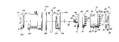
Turning now to Figure 1, the elements of a preferred embodiment of a
hydrotherapeutic jet 10 and mounting structure 100 are shown. The mounting
structure 100 houses the jet 10 and secures the jet to a wall 92, such as a
wall of a
hydrotherapeutic reservoir. The mounting structure, denoted generally as 100
comprises a rear wall mounting cap 102, a rear wall mounting 104, and a front
wall
mounting 108. In a preferred embodiment, an O-ring 106 is included between the
rear
wall mounting 104 and the wall 92.
The jet 10 comprises a jet body cap 12, a jet orifice cap 14, a jet body
16, and a face plate 18. As shown in Figure 2, a reservoir 26 is formed in
between the
jet body cap 12 and the jet orifice cap 14 when the two components are
connected. In
the preferred embodiment, the jet body cap 12, the jet orifice cap 14, the jet
body 16,
and the face plate 18 are permanently connected and sealed using sonic
welding, an
adhesive or cement to form a unitary jet structure 10 as shown in Figure 2.
Each
individual component of the jet structure 10 will now be described in detail.
With reference to Figures 1 and 2, the jet body cap 12 forms a first end
of the jet 10 and includes a tubular inlet 24 on which is formed an O-ring
seat 23.
20 The tubular inlet 24 is typically connected to a supply of pressurized
heated water.
The jet orifice cap 14 mates with the jet body cap 12, and the heated water
entering
the tubular inlet 24 fills the reservoir 26 between the two components. The
jet orifice
cap 14 is fixed to the jet body 16, and the jet body 16 is in fluid
communication with
the reservoir 26 through a plurality of rear nozzles 28 (Figure 1). Once the
reservoir
26 is filled with water, the fluid pressure increases forcing the fluid
through the rear
nozzles 28 into the jet body 16.
At the opposite end 21 of the jet body 16 is a second plurality of
nozzles 30, arranged in a plane and aligned with the first plurality of
nozzles 28 in a
one-to-one relationship. That is, each nozzle 28 has a corresponding nozzle 30
which
is aligned, preferably along a common axis, such that fluid expelled through a
nozzle
28 will form a stream which is directed into a corresponding nozzle 30. The
jet body
16 includes an outer ridge 32 having a slightly larger circumference than the
jet body
16, which forms a step 34 on the jet body exterior which positions the jet
body 16
inside the rear mounting 104. The face plate 18 comprises a cylindrical
portion 36
terminating in a beveled rim 38. When mounted to the jet body 16, the face
plate 18
CA 02211509 1997-08-08
-6-
extends beyond the nozzles 30 at an exit plane 40 in order to protect a user
from
contact with the nozzles 30.
Figures 3 and 4 show the jet body cap 12 in more detail. A toe 42
projects perpendicularly from a generally vertical outer surface 44 of the jet
body cap
12. As will be described below, the toe 42 is used to limit the rotation of
the jet body
16 between a maximum air intake position and a "no-air" intake position. The
tubular
inlet 24 is concentric with the jet body cap 12 and provides the entrance for
the fluid
to the jet. It can further be seen that the toe 42 includes webs 46 which
extend
perpendicular to the toe 42 and provide additional support for the toe 42. A
lip 48 is
provided which is inserted into the jet orifice cap 14 to secure the jet body
cap 12
therein.
Figure 5 illustrates the jet orifice cap 14 and its plurality of nozzles 28.
The nozzles 28 are arranged in a generally circular pattern as shown, with the
nozzles
28 aimed in a direction parallel to the axis 50 of the jet. The nozzles 28 are
preferably
molded in a unitary construction with the jet orifice cap 14, which may
include a
notch 52 along a circumferential edge which cooperates with a tab on the jet
body cap
(not shown) to align the two components.
In Figures 6-8, the jet body 16 is illustrated in greater detail. A jet
pattern of the preferred embodiment is shown comprising seven nozzles 30, six
along
a common circumference and one in the center. A cross-sectional view (Figure
7)
shows the cylindrical wall 56 defining a chamber 58 in the interior of the jet
body 16.
The nozzles 30 are of the same length and are shown protruding from an end 64
of the
jet body 16 with the ends 31 of the nozzles 30 terminating in a common plane.
A
teardrop-shaped slot or air orifice 66 is located on the side of the jet body
16 in the
cylindrical wall 56, and permits access to the chamber 58 of the jet body 16.
The slot
66 narrows or tapers in the circumferential direction from a maximum width 68
at a
first end 70 to a minimum width 72 at a second end 74. As will be described,
when a
supply of air is placed adjacent the slot 66, the rotation of the jet causes
more air to
enter the chamber 58 when the maximum width 68 of the slot 66 is adjacent the
air
supply, and when the jet is rotated away from this "maximum air intake"
position the
amount of air introduced into the chamber 58 decreases. Around the slot 66 is
a
groove which holds a sealing O-ring 78 to seal the jet body 16 when it is
placed in the
wall mounting 100.
CA 02211509 1997-08-08
_7_
In Figures 9 and 10 a face plate 18 is shown comprising a cylindrical
portion 80 terminating in a beveled rim 82. The face plate 18 has an exit
plane 84 and
the rim 82 includes an outer surface 88, with beveled areas 90 for use in
gripping the
face plate 18. The cylindrical portion 80 is sized such that when the face
plate 18 is
rigidly mounted to the jet body 16 in its intended configuration (see Figure
2), the exit
plane 84 of the face plate 18 extends beyond the nozzle tips 31 to protect a
user from
contact with the nozzles 30. The beveled surfaces 90 improve the grip of the
face plate
18, which is used to rotate the jet body within the mounting structure. A
granular
surface can be added to the face plate to further improve the gripping surface
of the
face plate 18, which is usually wet and slippery when in use.
In Figure 11, the rear wall mounting cap 102 is illustrated. The rear
wall mounting cap 102 fits into the rear wall housing and operates to secure
the jet
inside the housing. A tubular extension 110 is provided, which is sized to
receive the
tubular inlet 24 of the jet body cap 12 to protect the tubular inlet 24. The
rear wall
mounting cap 102 fits snugly into the rear wall housing 104 to close the
housing. At
the perimeter 114 of the rear wall mounting cap 102 is a tab 112 which
projects
radially from the perimeter 114. The tab 112 is used to align the rear wall
mounting
cap 102 within the rear wall mounting 104 using a notch 132 in the end of the
rear
wall mounting 104.
On the inner surface 116 of the rear wall mounting cap 102 is an
arcuate ridge 118 which opposes the jet body cap 12 when the rear wall
mounting cap
102 is in place in the rear wall housing 104 (see Figure 1). The arcuate
member 118
acts as a stop to limit the rotation of the jet 10 inside the mounting
structure when the
toe 42 of the jet body cap 12 is positioned between the ends 120 of the
arcuate
member 118. In this configuration, the jet is free to rotate between the ends
120 of the
arcuate member 118 on the rear wall mounting cap 102, but cannot rotate
outside of
this range. When the tab 112 on the rear wall mounting cap 102 is inserted
into the
notch 132, the ends 120 of the arcuate member 118 are positioned to coincide
with the
maximum air intake position and the "no-air" intake position of the jet body
16.
In Figure 12, the rear wall mounting 104 is shown as a cylindrical,
open housing including internal threads 122 and a circumferential lip 134 at
one end.
At the rear of the mounting is the notch 132 which cooperates with the tab 112
on the
rear wall mounting cap 102 to specify the relative positions of the mounting
104 and
the cap 102. A hollow stem 126 protrudes from a central outer wall 128 of the
rear
wall housing 104 and provides a channel by which air can be introduced into
the
CA 02211509 1997-08-08
_8-
interior of the rear wall housing 104. The hollow stem 126 is sized to be
inserted into
an air hose (not shown) and is provided with conical ridges 130 which
facilitate such
insertion and resist detachment of the air hose.
The stem 126 is positioned adjacent the slot 66 of the jet body when
the jet 10 is housed inside the rear wall mounting 104 such that air passing
through
the stem is introduced directly into the chamber 58 of the jet body 16 via the
slot 66.
As noted, the amount of air introduced is dependent upon the width of the slot
directly
adjacent the stem 126 such that the user can control the amount of air
injected into a
stream of water by rotating the position of the jet 10 in between the maximum
air
intake position and the "no-air" intake position defined concurrently by the
ends 64,70
of the slot 66 and the ends 120 of the arcuate member 118 on the rear wall
mounting
cap 102. The "no-air" intake position is defined by rotating the slot 66 just
beyond the
stem 126 such that no air is introduced into the chamber 58. Because the slot
66
gradually increases in width as the jet 10 is rotated towards the maximum air
intake
position, allowing a greater amount of air into the chamber 58, a user can
control the
amount of air which is introduced into the stream of water; in effect enabling
the user
to control the intensity of the hydrotherapy.
In Figure l, the front wall mounting 108 is shown having a cylindrical
portion 136 with external threads 138 which mate with the internal threads of
the rear
wall mounting 104 to fasten the two components together. When placed in an
opening
of the wall of a spa sized to receive the cylindrical member 136, the rotation
of the
front wall mounting 108 into the rear wall mounting 104 on respective sides of
the
wall 92 secures the j et 10 in place. The circumferential lip 140 on the front
wall
mounting 108 bears against the wall 92 on the front side 96 while the
circumferential
lip 134 on the rear wall mounting 104 bears against the wall 92 on the rear
side 98. In
this manner it can be seen that the jet 10, while mounted in the housing
structure 100,
can be secured to a wall of a spa or other hydrotherapeutic reservoir for
operation
thereat. An O-ring 106 is preferably located between the rear wall mounting
104 and
the wall 92 to reduce the possibility of leakage.
The extent to which the adjustable body assembly 10 extends into the
mounting structure 100 is determined by the length of the assembly 10 and the
abutment between a front face of the front wall mounting 108 and a plurality
of stops
215 (Figure 10) formed on the face plate 18. Surfaces facilitating rotation of
the
adjustable body assembly 10 within the wall fitting assembly 11 are provided
by
semicircular raised bearing surfaces 185, 187 on the jet body 16 and by the
interface
CA 02211509 1997-08-08
-9-
between the circular inner rim 101 of the front wall mounting 108 and the
cylindrical
portion 80 of the face plate 18.
The cylindrical portion 80 of face plate 18 further may include first and
second circumferential tabs 111, 113 projecting therefrom and diametrically
disposed
S from one another. These tabs 11 l, 113 have a spring bias to them which
allows them
to be depressed and thereafter snap behind an inner ridge of the front face of
the front
wall mounting 108, thereby retaining the face plate 18 in position, rotatably
mounted
within the front wall mounting 108. Each tab 111, 113 may further include a
chamfered leading edge to assist in depressing the respective tab 111, 112 as
it
contacts the front face of the front wall mounting 108 during insertion into
the interior
of the front wall mounting 108. Such chamfered leading edges make the face
plate 18
easier to insert than it is to remove.
The operation of the Gatling-type jet 10 will now be described. When
the jet 10 is placed in the housing structure 100, the stem of the rear wall
mounting
126 is aligned with the slot 66 of the jet body 16. The toe 42 of the jet body
cap 12 is
at the same time disposed between the ends 120 of the arcuate member 118 of
the rear
wall mounting cap 102 to limit the rotation of the jet between the maximum air
intake
position and the "no-air" intake position. The tubular inlet 24 of the jet 10
is
connected to a source of pressurized, heated water which enters the jet and
immediately fills the reservoir 26 between the jet body cap 12 and the jet
orifice cap
14. The reservoir 26 quickly fills and the building fluid pressure generated
therein is
released by the expulsion of the water through the nozzles 28 on the jet
orifice cap 14.
Each nozzle 28 directs a stream of the heated water across the chamber 58
within the
jet body 16, and into a corresponding second nozzle 30 positioned directly
opposite
the first nozzle 28. Each stream then passes through its second nozzle 30 and
out of
the jet 10, and as it passes through the second nozzle 30 a venturi effect is
created by
the second nozzle 30. The relationship of the size of the nozzles 28 to the
size of the
nozzles 30, both in orifice diameter and axial spacing, is responsible for
generation of
the venturi effect.
The user may also rotate the jet 10 using the beveled surface 90 of the
face plate 18, which is exposed to the exterior of the spa wall. Rotation of
the face
plate 18 is limited to the range between the maximum air intake position
corresponding to the alignment of the air supply channeled through the stem
126 of
the rear wall mounting 104 and the slot 66 of the jet body 16 at its maximum
width
70, and the "no-air" intake position corresponding to an alignment with the
stem just
CA 02211509 1997-08-08
-10-
beyond the slot. By selecting any position along this range, the user can
control the
amount of air introduced into the chamber 58 and therefore the intensity of
the
hydrotherapy effect.
It will be understood that the embodiment described herein are merely
exemplary and that a person skilled in the art may make many variations and
modifications without departing from the spirit and scope of the invention.
Such
modifications include, but are not limited to variation in the number and
positioning
of the nozzles 28, 30. Various numbers of Gatling jets may be placed in
various
locations of various fluid reservoirs such as spas, tubs, whirlpools, and the
like. In
Figure 13, two Gatling jets 10 are shown mounted in the inner wall 210 of a
fluid
reservoir or spa shell 211. All such variations and modifications are intended
to be
included within the scope of the invention as defined in the appended claims.