Note: Descriptions are shown in the official language in which they were submitted.
CA 02211745 1997-07-29
R'O 96123471 PCTlUS96100864
1
ABSORBENT ARTICLE
FIELD OF THE INVENTION
This invention relates to disposable absorbent articles, ~ and more
Y
particularly, to a disposable absorbent article having a ,liquid pervious
topsheet, a liquid impervious backsheet, and an absorbent core disposed
intermediate the topsheet and the backsheet.
The term "absorbent articles" as used herein refers to sanitary
napkins, pantiliners, and incontinence pads designed to absorb and retain
body fluids, such as menses and urine, discharged from the human body
when they are worn so as to cover the urogenital region.
BACKGROUND OF THE INVENTION
As is well known, an absorbent article advantaaeouslv used as a
", , ____ __ _
sanitary napkin has a liquid pervious topsheet, a liquid impervious
backsheet, and an absorbent core disposed intermediate the topsheet and
the backsheet. Such an absorbent article should conform to the wearer's
urogenital region, and be able to prevent leakage of body fluids, particularly
in the lateral direction. From these points of view, the absorbent article is
desired to be such that the topsheet, the core, and the backsheet extend
upwardly inclinedly toward the longitudinal ends of the absorbent article at
each of the longitudinally opposite end portions thereof, thereby assuming
the shape of a cup as a whole, and that so-called cuffs extending upwardly
inclinedly in a widthwise inwardly or outwardly are formed on both sides of
the longitudinally central portion of the absorbent article.
The term "longitudinal" as used herein refers to a direction extending
on the front and back of the body along the absorbent article worn in a
required state covering the wearer's urogenital region (a direction extending
substantially horizontally in the back-and-forth direction of the body when
the absorbent article is laid, in a flat form, substantially horizontally
below
the crotch region of the body standing upright). The term "widthwise" as
used herein refers to a direction extending on the right and left of the body
along the absorbent article worn in a required state covering the wearer's
urogenital region (a direction extending substantially horizontally in the
right-and-left direction of the body when the absorbent article is laid, in a
CA 02211745 1997-07-29
WO 96/23471 PCT/US96/00864
2
flat form, substantially horizontally below the crotch region of the body
standing upright).
A first proposal in the prior art for making the absorbent article cup-
shaped and forming cuffs, as stated above, is to shape the topsheet, the
core and the backsheet themselves such that the absorbent article takes
the cup-like form, and the topsheet and/or the backsheet forms the cuffs on
both sides of the longitudinally central portion of the absorbent article,
rather than shaping the topsheet, the core and the backsheet to an
originally flat form. As the prior references disclosing this first proposal
can
be cited the specification and drawings of U.S. Patent 3,575,174, the
specification and drawings of U.S. Patent 4,678,527 (Japanese Laid-Open
Patent Publication No. 76156/86), and the specification and .drawings of
U.S. Patent 4,834,739 (Japanese Laid-Open Patent Publication No.
4371 /90).
The absorbent article constructed in accordance with the first
proposal in the prior art involves the following problems: (1 ) The cost of
manufacturing considerably increases, because the topsheet, the core and
the backsheet have to be shaped to a required form. (2) The free end of
the cuff is contacted with the wearer's skin. Since the portion constituting
the cuff has no stretching properties, it is highly likely to cause discomfort
to
the wearer, leading to a poor feeling when wom.
A second proposal in the prior art for making the absorbent article
cup-shaped, as stated above, and forming the cuffs is to join elastically
expansile and contractile band-like elastic pieces, in an elastically
elongated state, to the topsheet and/or the backsheet on both sides in the
widthwise direction of the absorbent article. As the band-like elastic piece,
the use of a rubber strip or a thermoplastic elastomer strip has been
proposed. In the absorbent article equipped with such band-like elastic
pieces, the topsheet, core and backsheet are shaped like the cup, and the
topsheet and/or the backsheet forms the cuffs, owing to the contracting
action of the band-like elastic pieces. As the prior references disclosing
this
second proposal can be cited the specification and drawings of U.S. Patent
4,579,556, the specification and drawings of U.S. Patent 4,701,177, the
specification and drawings of U.S. Patent 4,758,241, the specification and
drawings of U.S. Patent 4,770,657, the specification and drawings of U.S.
Patent 4,944,735 (Japanese Laid-Open Patent Publication No. 193461185),
the specification and drawings of U.S. Patent 5,032,121, the specification
CA 02211745 1997-07-29
WO 96!23471 PCT/US96/00864
3
and drawings of U.S. Patent 5,074,856, the specification and drawings of
U.S. Patent 5,234,422, the specification and drawings of U.S. Patent
5,308,346, the specification and drawings of U.S. Patent 5,312,386
« (Japanese Laid-Open Patent Publication No. 277453/90), the specification
and drawings of European Laid-Open Patent Application 557,047
. (Japanese Laid-Open Patent Publication No. 220191/93), the specification
and drawings of European Laid-Open Patent Application 534,488, the
specification and drawings of European Laid-Open Patent Application
590,675, the specification and drawings of U.K. Patent 2,195,541
(Japanese Laid-Open Patent Publication No. 122451 /88), and the
specification and drawings of International Laid-Open Patent Application
92/07536 (Japanese Laid-Open Patent Publication No. 501409/94).
In the absorbent article constructed in accordance with the second
proposal in the prior art, elastic stretching properties are imparted to the
absorbent article, because of the presence of the band-like elastic pieces
formed of a rubber strip or a thermoplastic elastomer. This results in a
better feeling when worn than that of the absorbent article constructed in
. accordance with the first proposal. However, the absorbent article following
the second proposal poses the following problems: (1 ) The cost of
manufacturing considerably increases, because the use of the band-like
elastic piece made of a relatively expensive rubber strip or thermoplastic
elastomer strip is required. (2) It is necessary to create in the topsheet a
space for accommodating the band-like elastic pieces, and/or additionally
dispose a means for joining the elastic pieces to the topsheet and/or the
backsheet, as required. This adds to the cost of manufacturing.
A third proposal in the prior art for making the absorbent article cup-
shaped, as stated above, and forming the cuffs is to thermally bond the
longitudinally opposite ends and the widthwise outward portion of a
thermoplastic elastic piece, in an elastically, elongated state, to required
sites on the upper surface of the topsheet joined, as required, to the core
and the backsheet on each of both sides of the absorbent article. In the
absorbent article equipped with such .elastic pieces, the topsheet, core and
backsheet are shaped like the cup owing to the contracting action of the
elastic pieces. On both sides of the longitudinal central portion, the elastic
pieces are caused to extend upwardly inclinedly in a widthwise inward
direction, forming the cuffs. Such a third proposal is disclosed in Japanese
Laid-Open Utility Model Publication No. 86323/93.
CA 02211745 2000-03-02
4
In the absorbent article constructed in accordance with the third proposal in
the prior art, the thermoplastic elastic pieces themselves which are thermally
bonded
to the topsheet form cuffs on both sides of the longitudinally central
portion.
Moreover, thermal bonding can be carried out relatively simply. Thus, some
improvement is achieved on the aforementioned problems facing the absorbent
articles constructed in accordance with the first and second proposals. The
absorbent article following the third proposal, however, presents with the
following
problems: (1 ) The elastic piece is in the form of an ordinary film, with its
front and
back being planar. Thus, it has a relatively large area of contact with the
wearer's
skin, and the feeling of the absorbent article when worn is still not
satisfactory. (2)
The thermoplastic elastic piece needs to be formed of a material having
sufficient
elasticity, and thus relatively expensive, adding considerably to the cost of
manufacturing. (3) The thermoplastic elastic piece need to be formed of a
material
having sufficient elasticity, which usually is considerably different from the
material of
the topsheet in terms of the molecular structure. Hence, it is difficult to
thermally
bond the thermoplastic elastic piece to the topsheet fully satisfactorily. (4)
The core
and the backsheet are joined to the tophseet to form the body of the absorbent
article. In this state, the thicknesses at the longitudinally opposite end
portions and
the widthwise opposite end portions of the topsheet have been sharply varied,
because there is no core there. Afterwards, the thermoplastic elastic pieces
are
thermally bonded to the topsheet, thus posing difficulty with the thermal
bonding of
the thermoplastic elastic pieces.
The present invention has been accomplished in the light of the above-
mention facts. It is an object of an aspect of the invention to provide an
absorbent
article which takes the form of a cup as a whole, forms upwardly extending
cuffs on
both sides of the longitudinally central portion thereof, and yet produces a
fully
satisfactory feeling when worn.
It is an object of an aspect of the present invention to provide an absorbent
article which takes the form of a cup as a whole, forms upwardly extending
cuffs on
both sides of the longitudinally central portion thereof, and yet produces a
fully
satisfactory feeling when worn, and additionally can be manufactured for a
sufficiently low cost.
It is an object of an aspect of the present invention to provide a
manufacturing
process permitting a sufficiently simple and inexpensive
CA 02211745 1997-07-29
WO 96!23471 PCT/US96/00864
manufacture of an absorbent article which takes the form of a cup as a
whole, and forms upwardly extending cuffs on both sides of the
longitudinally central portion thereof.
SUMMARY OF THE INVENTION
According to one aspect of the present invention for overcoming the
first technical challenge, elastic pieces to be joined to at least one of the
topsheet and the backsheet are formed from a web deformed at least
partially in a non-planar configuration by machining.
That is, according to one aspect of the present invention, there is
provided an absorbent article comprising a liquid pervious topsheet, a liquid
impervious backsheet, an absorbent core disposed intermediate the
topsheet and the backsheet, and a pair of band-like elastic pieces arranged
on both sides of the absorbent article and joined to at least one of the
topsheet and the backsheet in a longitudinally elastically elongated state;
the topsheet, the backsheet, and the core being caused to extend upwardly
inclinedly toward the longitudinal ends of the absorbent article at each of
the longitudinally opposite end portions thereof, and the elastic pieces
being caused to extend upwardly on both sides of the longitudinally central
portion of the absorbent article, owing to the contracting action of the
elastic
pieces; wherein
each of the elastic pieces is formed from a web deformed at least
partially in a non-planar configuration by machining.
In order to solve the second technical challenge as well as the first
technical challenge, a thermoplastic film lacking required elasticity prior to
machining, preferably a polyolefin film such as a polyethylene or
polyethylene blended film, is used as the web formed into the elastic piece
by machining. The machined synthetic resin film includes deformed
portions deformed in a non-planar configuration by machining, and
undeformed portions retained in a substantially planar configuration.
Furthermore, the undeformed portions are caused to extend longitudinally,
and the contracting action of each of the elastic pieces is generated mainly
by the undeformed portions. When the elastic pieces are subjected to an
applied elongation, the undeformed portions undergo a substantially
molecular-level deformation and the deformed portions undergo a
substantially geometric deformation.
CA 02211745 1997-07-29
WO 96/23471 PCT/US96/00864
6
The area rate of the undeformed portions of each of the elastic
pieces, calculated on the assumption that the elastic pieces are in a non-
~elongated state and the deformed portions are in a planar configuration, is 1
to 30%, preferably 3 to 20%, more preferably 5 to 12°~. If the area
rate of
the undeformed portions is too large, discomfort the wearer feels upon
contact with the skin increases. If the area rate of the undeformed portions
is too small, by contrast, the contracting action for shaping the absorbent
article like a cup tends to be diminished markedly.
Preferably, each of the elastic pieces is folded back along a
longitudinally extending fold-back line to have a two-layer configuration, and
the fold-back lines define the upper edges on both sides of the longitudinal
central portion of the absorbent article. If the deformed portions and the
undeformed portions of each of the elastic pieces extend longitudinally
uninterruptedly in a widthwise side-by-side relationship, the fold-back line
can be situated at the undeformed portion or the deformed portion. When
the fold-back line is situated at the undeformed portion, the upper edge of
the elastic piece (the fold-back line) becomes relatively sharp, providing a
good contact with the wearer's skin. When the fold-back line is situated at
the deformed portion, the upper edge of the elastic piece (the fold-back line)
becomes dull, giving the wearer a gentle feeling when wearing the
absorbent article.
Preferably, at least part of each of the elastic pieces is disposed
above the topsheet, the core is smaller than the topsheet, the longitudinally
opposite ends of the core are located inwardly of the longitudinally opposite
ends of the topsheet, and at least the undeformed portions of each of the
elastic pieces are joined to the topsheet in the region where the
longitudinally opposite ends of the core are situated. Each of the elastic
pieces has at least the undeformed portions thermally bonded to the
~topsheet at a plurality of spaced apart sites in the region where the
longitudinally opposite ends of the core are situated. By joining the elastic
pieces to the topsheet in the region where the longitudinally opposite ends
of the core are situated, the core having a relatively high rigidity is
effectively utilized for shaping the absorbent article like a cup, and the
topsheet and the backsheet are prevented from becoming locally bent at the
corners of their front ends.
In a preferred embodiment of the invention, each of the elastic pieces
is disposed above the topsheet such that the fold-back line defines the
CA 02211745 1997-07-29
WO 96/23471 PCT/US96/00864
7
widthwise inward edge, each of the elastic pieces is joined to the topsheet
at the widthwise outward edge and the longitudinally opposite ends of each
of the elastic pieces, and the elastic pieces are caused to extend upwardly
. inclinedly in a widthwise inward direction at the longitudinally central
portion
of the absorbent article, owing to the contracting action of the elastic
pieces.
Each of the elastic pieces in an elastically elongated configuration includes,
in the longitudinally central portion, an additional portion which extends
further widthwise outwardly from the widthwise outward edge of the elastic
piece joined to the topsheet, and which is then folded back to extend
widthwise inwardly. The additional portion of the elastic piece may also be
caused to extend upwardly inclinedly in a widthwise outward direction owing
to the contracting action of the elastic pieces. The widthwise outward
region of the additional portion of each of the elastic pieces can constitute
a
wing to be folded back onto the outside surface of panties. In another
preferred embodiment of the invention, each of the elastic pieces is
disposed such that the fold-back line defines the widthwise outward edge,
each of the elastic pieces in an elastically elongated configuration is caused
to extend widthwise outwardly beyond both side edges of the topsheet in
the longitudinally central portion, each of the elastic pieces is joined to at
least one of the topsheet and the backsheet at the widthwise outward edges
and the longitudinally opposite ends of at least one of the topsheet and the
backsheet, and the elastic pieces are caused to extend upwardly inclinedly
in a widthwise outward direction in the longitudinally central portion, owing
to the contracting action of the elastic pieces.
According to another aspect of the present invention for overcoming
the first technical challenge, each of the elastic pieces is disposed below
the backsheet, the widthwise outward portions of the topsheet are not joined
to the elastic pieces in the longitudinally central portion of the absorbent
article, and the widthwise outward portions of the topsheet are caused to
extend upwardly in the longitudinally central portion of the absorbent
article,
owing to the contracting action of the elastic pieces.
That is, according to another aspect of the present invention, there is
provided an absorbent article comprising a liquid pervious topsheet, a liquid
. impervious backsheet, an absorbent core disposed intermediate the
topsheet and the backsheet, and a pair of band-like elastic pieces arranged
on both sides of the absorbent article and joined to at least one of the
topsheet and the backsheet in a longitudinally elastically elongated state;
CA 02211745 1997-07-29
WO 96123471 PCTIUS96/00864
8
the topsheet, the backsheet, and the core being caused to extend upwardly
inclinedly toward the longitudinal ends of the absorbent article at each of
the longitudinally opposite end portions thereof, and the widthwise outward
portions of the topsheet being caused to extend upwardly on both sides of
the longitudinally central portion of the absorbent article, owing to the
contracting action of the elastic pieces; wherein '
each of the elastic pieces is disposed below the backsheet, and the
widthwise outward portions of the topsheet are not joined to the elastic
pieces in the longitudinally central portion of the absorbent article.
Preferably, at least on both sides of the longitudinally central portion,
the topsheet is folded back along fold-back lines defining its widthwise
outward edges to have a two-layer configuration, and the two-layered
widthwise outward portions of the topsheet extend upwardly inclinedly in a
widthwise outward direction. Preferably, each of the elastic pieces has a
portion which is caused to extend widthwise outwardly beyond the topsheet
in the longitudinally central portion of the absorbent article, and which
constitutes a wing to be folded back onto the outside surface of panties.
According .to still another aspect of the present invention for
overcoming the third technical challenge, a pair of elastically elongated
starting webs for forming the pair of elastic pieces are joined to a starting
web for forming one of the topsheet and the backsheet before a starting
web for forming the other of the topsheet and the backsheet and the core
are joined to the starting web .for forming the one of the topsheet and the
backsheet.
That is, according to still another aspect of the present invention,
there is provided a process for manufacturing an absorbent article
comprising a liquid pervious topsheet, a liquid impervious backsheet, an
absorbent core disposed intermediate the topsheet and the backsheet, and
a pair of band-like elastic pieces arranged on, both sides of the absorbent
article and joined to at least one of the topsheet and the backsheet in a
longitudinally elastically elongated state; the topsheet, the backsheet, and
the core being caused to extend upwardly inclinedly toward the longitudinal
ends of the absorbent article at each of the longitudinally opposite end
portions thereof, and either the elastic pieces or the widthwise outward .
portions of the topsheet being caused to extend upwardly on both sides of
the longitudinally central portion of the absorbent article, owing to the
contracting action of the elastic pieces; said process including the steps of
CA 02211745 1997-07-29
WO 96123471 PCT/US96/00864
9
joining to a first web for forming one of the topsheet and the
backsheet a pair of elastically elongated second webs for forming the pair
of elastic pieces at predetermined sites, and then
~, joining to the first web for forming the one of the topsheet and the
backsheet a third web for forming the other of the topsheet and the
backsheet and the core at predetermined sites.
In a preferred embodiment, the first web, the second web and the
third web are composed of a thermoplastic film, and the joining of the
second web and that of the third web to the first web are each performed by
thermal bonding.
In the absorbent article constructed in accordance with one aspect of
the present invention, each the elastic pieces extending upwardly on both
sides of the longitudinally central portion of the absorbent article to form
cuffs is formed from a web deformed at least partially in a non-planar
configuration by machining. Such a web has a considerably decreased
area of contact with the wearer's skin as compared with an entirely planar
web which has not been machined. For this and other reasons, discomfort
caused to the wearer, if any, is much less. Thus, the feeling of the
absorbent article when worn is markedly improved over that of a
conventional absorbent article. When a thermoplastic film, especially, a
polyolefin film such as a polyethylene or polyethylene blended film, is used
as the web to be formed into the elastic piece by machining, the cost of the
elastic piece as the material is sufficiently low. Moreover, the molecular
structure of the topsheet and/or the backsheet and that of the elastic piece
are rendered substantially the same or similar to each other, thereby
enabling the thermal bonding of the elastic piece to the topsheet and/or the
backsheet to be performed with ease. Thus, it becomes possible to lower
the cost of manufacturing sufficiently and manufacture the absorbent article
sufficiently easily.
In the absorbent article constructed in accordance with another
aspect of the present invention, the widthwise outward portions of the
. , topsheet, rather than the elastic pieces, extend upwardly on both sides of
the longitudinally central portion owing to the contracting action of the
elastic pieces, to form cuffs. Even if the topsheet itself gives, in essence,
discomfort to the wearer because of the machining for making it liquid
pervious, the discomfort is sufficiently less, thus improving the feeling of
the
CA 02211745 1997-07-29
WO 96/23471 PCTIUS96/00864
absorbent article when worn, in comparison with that of a conventional
absorbent article.
In the manufacturing process constituted in accordance with still
another aspect of the present invention, elastically elongated webs for
forming a pair of elastic pieces are joined to a web for forming one of the
topsheet and the backsheet, before a web for forming the other of the
topsheet and the backsheet and the core are joined to the web for forming
the one of the topsheet and the backsheet (accordingly, when the web for
forming the one of the topsheet and the backsheet is sufficiently uniform in
thickness, etc. throughout it). Therefore, required excellent joining can be
achieved sufficiently easily.
BRIEF DESCRIPTION OF THE DRAWINGS
While the specification concludes with claims particularly pointing out
and distinctly claiming the present invention, it is believed that the present
invention will be better understood from the following description in
conjunction with the following drawings, in which like reference numbers
identify identical elements and wherein:
Fig. 1 is a perspective view showing an embodiment of a sanitary
napkin constructed in accordance with the present invention;
Fig. 2 is a plan view showing the sanitary napkin of Fig. 1 with the
elastic pieces elongated to make the entire napkin flat.
Fig. 3 is a cross sectional view taken on line 3-3 of Fig. 1.
Fig. 4 is a plan view showing part of the web used preferably to form
the elastic pieces of the sanitary napkin illustrated in Fig. 1.
Fig. 5 is a perspective view showing part of the web illustrated in Fig.
4.
Fig. 6 is a perspective view showing part of the web illustrated in Fig.
4 in an elastically somewhat elongated state.
Fig. 7 is a perspective view showing part of the web illustrated in Fig.
4 in a more elastically elongated state than the state of Fig. 6.
Fig. 8 is a diagram showing the relationship between a longitudinally ,
exerted tensile force and elongation in the web illustrated in Fig. 4, and the
relationship between a longitudinally exerted tensile force and elongation in
an ordinary flat web before being converted into the web of Fig. 4 by
machining.
CA 02211745 1997-07-29
R'O 96/23471 PC"T/US96/00864
11
Fig. 9 is a perspective view showing a processing means
advantageously used to form the web of Fig. 4.
Fig. 10 is a perspective view showing the web of Fig. 4 folded back
along the undeformed portion.
Fig. 11 is a perspective view showing the web of Fig. 4 folded back
- along the deformed portion.
Fig. 12 is a perspective view showing another embodiment of a
sanitary napkin constructed in accordance with the present invention.
Fig. 13 is a plan view, similar to Fig. 2, showing the sanitary napkin
of Fig. 12 with the elastic pieces elongated to make the entire napkin flat.
Fig. 14 is a cross sectional view taken on line 14-14 of Fig. 12.
Fig. 15 is a perspective view showing still another embodiment of a
sanitary napkin constructed in accordance with the present invention.
Fig. 16 is a plan view, similar to Fig. 2, showing the sanitary napkin
of Fig. 15 with the elastic pieces elongated to make the entire napkin flat.
Fig. 17 is a cross sectional view taken on line 17-17 of Fig. 15.
Fig. 18 is a cross sectional view, similar to Fig. 3, showing a modified
example of the sanitary napkin illustrated in .Fig. 1.
Fig. 19 is a cross sectional view, similar to Fig. 3, showing a modified
example of the sanitary napkin illustrated in Fig. 12.
Fig. 20 is a plan view, similar to Fig. 2, showing another modified
example of the sanitary napkin illustrated in Fig. 1.
Fig. 21 is a cross sectional view, similar to Fig. 3, of the sanitary
napkin illustrated in Fig. 20.
Fig. 22 is a cross sectional view, similar to Fig. 3, showing a modified
example of the sanitary napkin illustrated in Fig. 20.
Fig. 23 is a plan view, similar to Fig. 2, showing still another modified
example of the sanitary napkin illustrated in Fig. 1.
Fig. 24 is a cross sectional view, similar to Fig. 3, of the sanitary
napkin illustrated in Fig. 23.
Fig. 25 is a plan view, similar to Fig. 2, showing a modified example
of the sanitary napkin illustrated in Fig. 23.
Fig. 26 is a cross sectional view, similar to Fig. 3, of the sanitary
napkin illustrated in Fig. 25.
Fig. 27 is a plan view, similar to Fig. 2, showing still . another
embodiment of a sanitary napkin constructed in accordance with the
present invention.
CA 02211745 1997-07-29
WO 96/23471 PCT/US96/00864
12
Fig. 28 is a cross sectional view, similar to Fig. 3, of the sanitary
napkin illustrated in Fig. 27.
DETAILED DESCRIPTION OF THE INVENTION
Preferred embodiments of the present invention will be described in
more detail with reference to the accompanying drawings. -
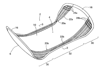
Figs. 1 to 3 show a sanitary napkin, an embodiment of an absorbent
article constructed in accordance with the present invention. The napkin
shown entirely at the numeral 2, as will be understood from the following
description, is not in a substantially flat form, but is cup-shaped as
illustrated in Fig. 1, owing to the contracting action of elastic pieces. In
Fig.
2, the entire napkin 2 is shown in a substantially flat state with its elastic
pieces elongated elastically. The napkin 2 indicated in Figs. 1 to 3 has a
liquid pervious topsheet 4, a liquid impervious backsheet 6, and an
absorbent core 8 disposed intermediate the topsheet 4 and the backsheet
6.
The topsheet 4 importantly should permit bodily discharges from the
wearer to rapidly penetrate the absorbent core 8, and should not cause
excessive discomfort to the wearer when it is contacted with the wearer's
skin. The topsheet 4 can be formed advantageously from materials, such as
woven or nonwoven fabrics of natural or synthetic fibers; apertured
thermoplastic films; porous foams; reticulated foams; reticulated
thermoplastic films; and thermoplastic scrims. In the illustrated
embodiment, the topsheet 4 comprises a primary topsheet layer 10 and a
secondary topsheet layer 12. In the state shown in Fig. 2, the primary
topsheet layer 10 is nearly rectangular overall, with its longitudinally (up-
and-down in Fig. 2) opposite edges extending convexly arcuately, and its
opposite side edges extending straightly at the longitudinally opposite end
portions, but extending concavely arcuately at the longitudinally central
portion. Such primary topsheet layer 10 can be preferably formed from an
apertured polyolefinic ~Im as disclosed in the specification and drawings of
U.S. Patents 3,929,135, 4,324,246, 4,342,314, 4,463,045 and 5,006,394. -
The secondary topsheet layer 12 is joined to the inner surface, i.e.,
undersurface, of the primary topsheet layer 10. The secondary topsheet
layer 12 is rectangular, and its longitudinal and widthwise dimensions are
smaller than the longitudinal and widthwise dimensions of the primary
topsheet layer 10, with the peripheral edge portion of the primary topsheet
CA 02211745 2000-03-02
WO 961I3d71 PCflUS9610086.s
13
layer 10 extending beyond the peripheral edge portion of the secondary
topsheet layer 12. The secondary topsheet layer 12 desirably has the
function to disperse a body fluid, which has passed through the primary
topsheet layer 10, mainly in the longitudinal direction and cause it to flow
into the absorbent core 8. Such secondary topsheet layer 12 can be formed
preferably from a natural or synthetic nonwoven fabric. Particularly
preferred nonwovens for forming the secondary topsheet layer 12 include a
_ - nonwoven fabric of spunbond polypropylene fibers designated P-9 available
from the Fiberweb Corporation of Simpsonville, South Carolina, USA, under
the tradename CELESTRA; and a nonwoven fabric formed of bicomponent
fibers which have a polyethylene sheath and a polyesters corela
polyethylene sheath and a polypropylene core, the fabric available from the
Navix Company, of Japan, as S2146. The primary topsheet layer 10 and
the secondary topsheet layer 12 are advantageously joined together by
adhesive bonding via a suitable adhesive, ultrasonic welding, or thermal
bonding which is carried out in a multiplicity of discrete areas. In Fig. 3,
the
areas of bonding, welding or thermal bonding between the primary topsheet
layer 10 and the secondary topsheet layer 12 are indicated by heavy solid
lines for convenience of illustration.
The backsheet 6 importantly has the function to prevent body fluids
absorbed to the absorbent core 8 from flowing out of the napkin and soiling
the wearer andlor the wearer's clothing. The backsheet 6 can be
advantageously formed from a flexible liquid impervious thermoplastic film
such as a polyolefinic film. Particularly preferred films for forming the
backsheet 6 include a low density polyethylene film 0.01 to 0.05 mm,
particularly, about 0.025 mm, in thickness. Such a polyethylene film is sold
by the Ethyl Corp., Visqueen Division, as Model XP-3385 and by the
Clopay Corp. of Cincinnati, Ohio, USA, as SOFLEXX 1401. In the
illustrated embodiment, the backsheet 6 has a shape and dimensions which
are substantially the same as the shape and dimensions of the primary
topsheet layer 10 of the topsheet 4. The primary topsheet layer 10 of the
topsheet 4 and the backsheet 6 are thermally bonded unintemrptedly
throughout their peripheral edges. For convenience of illustration, the area
16 of thermal bonding between the primary topsheet layer 10 and the
backsheet 6 is represented by intersecting diagonal lines in Fig. 2, and
heavy solid lines in Fig. 3. If desired, the primary topsheet layer 10 and the
backsheet 6 may be joined together in other suitable manner, such as
CA 02211745 2000-03-02
wo ~rz3on per~s96ioos6,s
14
bonding with an adhesive. Where necessary, a pressure sensitive
adhesive for detachably securing the napkin 2 to required sites on the inner
surface of the undergarment of the wearer can be applied to the outside
surface, i.e., the undersurface, of the backsheet 6 in one or more
longitudinally extending bands. A suitable pressure sensitive adhesive is
Century Adhesive A-305-IV sold by Century Adhesive Corp. of Columbus,
Ohio, USA. In applying the pressure sensitive adhesive to the underside of
the backsheet 6, it is desirable to cover the pressure sensitive adhesive
with a silicone coated paper in order to prevent its soiling prior to use.
Figs. 1 to 3, especially Fig. 3, will be referred to for further
explanation. The absorbent core 8 disposed between the topsheet 4 and
the backsheet 6 importantly functions to absorb and retain body fluids that
have penetrated the topsheet 4 after discharge from the wearer. Such
absorbent core 8 can be advantageously formed from materials, such as
comminuted wood pulp called airfelt; ueped cellulose wadding; meltblown
polymers; chemically stiffened, modified, or crosslinked cellulosic fibers;
absorbent foams; layers of tissue paper; absorbent gelling materials
(materials gelling when absorbing liquids); or any suitable combinations of
these. The longitudinal and widthwise dimensions of the illustrated core 8
are smaller than the longitudinal and widthwise dimensions of the primary
topsheet layer 10 and the backsheet 6, with the core 8 being situated
inwardly of the areas 16 of thermal bonding between the primary topsheet
layer 10 and the backsheet 6. Advantageously, the longitudinal and
widthwise dimensions of the secondary topsheet layer 12 in the topsheet 4
are somewhat smaller than or substantially equal to the longitudinal and
widthwise dimensions of the core 8. The top surface of the core 8 is joined
to the undersurface of the secondary topsheet layer 12, while the
undersurface of the core 8 is joined to the inner surface or top surface of
the
backsheet.6. The joining of the core 8 and the secondary topsheet layer 12
and the joining of the core 8 and the backsheet fi are advantageously
achieved by bonding via a suitable adhesive which is carried out in a
multiplicity of discrete areas. If desired, the core 8 may be joined to the
secondary topsheet layer 12 andlor the backsheet 6 in other suitable
manner, such as ultrasonic welding or thermal bonding. In Fig. 3, the
discrete areas 18 of bonding, welding or thermal bonding between the core
8 and the secondary topsheet layer 12, and the discrete areas 19 of
CA 02211745 1997-07-29
WO 96!23471 PG"T/US96/00864
bonding, welding or thermal bonding between the core 8 and the backsheet
6 are indicated by heavy solid lines for convenience of illustration.
With further reference to Figs. 1 to 3, the illustrated napkin 2
constructed in accordance with the present invention further includes a pair
of band-like elastic pieces 20a and 20b. Each of the band-like elastic
pieces 20a and 20b is situated above the topsheet 4 in an elastically
elongated state, and is joined to the topsheet 4 at required sites. As will be
easily understood by reference to Fig. 3, the respective elastic pieces 20a
and 20b are folded back along longitudinally extending fold-back lines 22a
and 22b to have a two-layer configuration, and are arranged on both sides
of the topsheet 4, with the fold-back lines 22a and 22b located widthwise
inwardly. In the state illustrated in Fig. 2. in which the elastic pieces 20a
and 20b are elongated to make the entire napkin 2 flat, the widthwise
inward edges of the elastic pieces 20a and 20b, i.e., the fold-back lines 22a
and 22b, extend substantially straightly in the longitudinal direction. On the
other hand, the widthwise outward edge and longitudinally opposite edges
of each of the elastic pieces 22a and 22b are rendered consistent with the
widthwise outward edge and opposite edges of the topsheet 4. Each of the
elastic pieces 20a and 20b has the respective layers of the two-layer
structure thereof thermally bonded together, and is thermally bonded to the
primary topsheet layer 10 of the topsheet ~4, at the widthwise outward edge
and longitudinally opposite edges thereof. Such areas 26a and 26b of
thermal bonding are represented by intersecting diagonal lines in Fig. 2,
and heavy solid lines in Fig. 3, for convenience of illustration. As one will
easily understand by referring to Figs. 2 and 3, the areas 26a and 26b of
thermal bonding are substantially conformed to the main part of the above-
mentioned area 16 of thermal bonding between the primary topsheet layer
10 of the topsheet 4 and the backsheet 6 (i.e., that part in the area 16 of
heating which excludes the widthwise central area of the longitudinally
opposite edges where the elastic pieces 20a and 20b are not present).
Furthermore, each of the elastic pieces 20a and 20b has the respective
. layers of the two-layer structure thereof thermally bonded together, and is
thermally bonded to the primary topsheet layer 10 of the topsheet 4, at a
plurality of longitudinally spaced apart sites in each of the longitudinally
opposite end portions, and more specifically, at three sites 28a and 28b of
thermal bonding delineated in solid lines in Figs. 1 and 2, by operating a
thermal bonding tool (not shown) there. Importantly, at least part of the
CA 02211745 1997-07-29
WO 96!23471 PCTIUS96/00864
16
plurality of thermal bonding sites 28a and 28b is present within the region
where the longitudinally opposite end portions of the core 8 are located
below the primary topsheet layer 10 of the topsheet 4. In the illustrated
embodiment, as will be understood from Fig. 2, one thermal bonding site
28a and one thermal bonding site 28b located at the outermost position in
each of the longitudinally opposite end portions of the elastic pieces 20a
and 20b are situated outwardly of the longitudinal end of the core 8.
Whereas the remaining two thermal bonding sites 28a and 28b are located
inwardly of the longitudinal end of the core 8. If desired, instead of thermal
bonding, other suitable method may be employed to join the elastic pieces
20a and 20b to the primary topsheet layer 10 of the topsheet 4 (where
necessary, while joining the respective layers of their two-layer structure to
each other).
As stated above, the elastic pieces 20a and 20b are located above
the topsheet 4 in an elongated state, and are thermally bonded thereto at
the areas 26a and 26b of thermal bonding as well as the sites 28a and 28b
of thermal bonding. Afterwards, the force that has maintained the elastic
pieces 20a and 20b in an elongated condition is released. As a result, the
non-thermally bonded portions of the elastic pieces 20a and 20b elastically
contract, and thus, the elastic pieces 20a and 20b try to restore their
original lengths at least partially. Owing to this contracting action
generated
in the elastic pieces 20a and 20b, the topsheet 4, the backsheet 6 and the
core 8 are displaced to extend upwardly inclinedly toward the longitudinally
opposite ends in each of the longitudinally opposite end portions 30, as
clearly illustrated in Fig. 1. Thus, the napkin 2 is brought into the shape of
a
cup as a whole. In addition, in the longitudinally central portion 32, each of
the elastic pieces 20a and 20b is caused to extend upwardly inclinedly in a
widthwise inward direction (accordingly, toward the aforementioned fold-
back lines 22a and 22b). Thus, on both sides of the longitudinally central
portion 32 of the napkin 2, the elastic pieces 20a and 20b form cuffs which
function as barriers for preventing body fluids from leaking widthwise
outwardly. The elongation of the elastic pieces 20a and 20b during thermal
bonding depends on the entire configuration and dimensions of the napkin
itself. Normally, however, it is preferred to set the entire length at
elongation at about 110 to 160%, especially, about 115 to 145%, of the
entire length at non-elongation.
CA 02211745 1997-07-29
WO 96!23471 PCT/US96/00864
17
According to our experience, if thermal bonding is not performed at
the sites 28a and 28b of thermal bonding, the primary topsheet layer 10 of
the topsheet 4 and the backsheet 6 tend to be locally bent at the four
corners of the napkin 2 owing to the contracting action of the elastic pieces
20a and 20b, since the primary topsheet layer 10 of the topsheet 4 and the
backsheet 6 have relatively low stiffness. When thermal bonding is
performed at the sites 28a and 28b of thermal bonding, on the other hand,
the elastically contracting action of the elastic pieces 20a and 20b is
locally
eliminated between the sites 28a and 28b of thermal bonding. Also, the
elastic pieces 20a and 20b are locally joined to the relatively highly stiff
core 8 via the primary topsheet layer 10, whereby the contracting action of
the elastic pieces 20a and 20b is effectively transmitted to . the core 8.
Consequently, the undesirable local bending of the primary topsheet layer
of the topsheet 4 and the backsheet 6 at the four corners of the napkin 2
is prevented, and the topsheet 4, backsheet 6 and core 8 are caused to
extend upwardly inclinedly toward the longitudinally opposite ends, as
desired, in each of the longitudinally opposite end portions 30.
In the napkin 2 constituted in accordance with the present invention,
the elastic pieces 20a and 20b are formed from a web deformed at least
partially in a non-planar configuration by machining. Particularly preferably
usable is a web comprised of a thermoplastic film, especially, a polyolefinic
film such as a polyethylene film, which includes, in a suitable combination,
deformed portions deformed in a non-planar configuration by machining,
and undeformed portions retained in a substantially planar configuration.
Preferably, the undeformed portions extend longitudinally in a continuous or
discrete manner. When the elastic pieces 20a and 20b are formed from a
web including the deformed portions and the longitudinally extending
undeformed portions, the contracting action of the elastic pieces 20a and
20b joined in an elastically elongated state to the topsheet 4 is generated
mainly by the elastic restoring effect of the undeformed portions, as will be
clearly understood from the description to be given below.
Figs. 4 and 5 show a web 34 that can be used preferably for forming
the elastic pieces 20a and 20b. This web 34 is composed of deformed
portions 36 deformed in a non-planar configuration by machining, and
undeformed portions 38 retained in a substantially planar configuration. As
will be seen clearly from Fig. 4, the deformed portions 36 and the
undeformed portions 38 are arranged alternately in a side-by-side
CA 02211745 1997-07-29
WO 96/23471 PCTIUS96/00864
18
relationship in the widthwise direction shown by arrows 43 (in the right-and-
left direction in Fig. 4), and are caused to extend uninterruptedly in the
longitudinal direction shown by arrows 44 (in the up-and-down direction in
Fig. 4). As will be understood by reference to Fig. 5, the deformed portion
36 includes a primary deformed portion 40, and secondary deformed
portions 42 located on both sides in its widthwise direction. The primary -
deformed portion 40 takes a substantially uniform nearly wavy form in its
longitudinal cross section, and takes a substantially horizontally extending
straight form in its widthwise cross section. The secondary deformed
portion 42 is a region of transition from the primary deformed portion 40 and
the undeformed portion 38. The proportion of the undeformed portions 38
in the web 34 is about 1 to 30%, preferably 3 to 20°~, more preferably
5 to
12%, when calculated as the rate of area on the assumption that the web 34
is in a non-elongated state and the deformed portions 36 (including the
primary deformed portions 40 and the secondary deformed portions 42) are
in an undeformed planar configuration, that is, the state illustrated as such
in Fig. 4 (a non-elongated plan view). In other words, the proportion of the
deformed portions 36 (including the primary deformed portions 40 and the
secondary deformed portions 42) in the web 34 is about 70 to 99°~,
preferably 80 to 97%, more preferably 88 to 95°r6, when calculated as
the
rate of area on the assumption that the web 34 is in a non-elongated state
and the deformed portions 36 (including the primary deformed portions 40
and the secondary deformed ~ portions 42) are in an undeformed planar
configuration, that is, the state illustrated as such in Fig. 4 (a non-
elongated
plan view). If the proportion of the undeformed portions 38 in the web 36 is
too high, the elastic elongation of the elastic pieces 20a and 20b tends to
become relatively difficult. If the proportion of the undeformed portions 38
in the web 36 is too low, the contracting action of the elastic pieces 20a and
20b joined in an elastically elongated state to the topsheet 4 is minimal,
making it difficult to shape the napkin 2 into a desired cup-like form.
Furthermore, the following fact should also be noticed in regard to the
proportion of the undeformed portions 38 in the web 36: Since the
deformed portions 36 are in a non-planar configuration, they touch the skin
of the napkin 2 wearer only locally at a plurality of small spaced apart ,
regions. Consequently, discomfort they cause to the wear is limited, if any.
In contrast, if the proportion of the undeformed portions 38 is too high and
the undeformed portions 38 are the main source of contact with the skin of
CA 02211745 1997-07-29
WO 96/23471 PG"T/LTS96/00864
19
the napkin wearer, the undeformed portions 38 in a planar configuration
touch the wearer's skin uninterruptedly over a relatively large area. Thus,
they cause considerable discomfort to the wearer. Generally, the width W1
of the deformed portion 36 is 0.25 to 50.80 mm (0.01 to 2.00 inches),
preferably, 3.18 to 25.40 mm (0.13 to 1.00 inch), while the width W2 of the
undeformed portion 38 is 0.25 to 12.70 mm (0.01 to 0.50 inch), preferably,
0.76 to 6.35 mm (0.03 to 0.25 inch).
The web 34 shown in Figs. 4 and 5 exhibits desired elasticity as the
elastic pieces 20a and 20b in the longitudinal direction indicated by arrows
44. When a longitudinal tensile force is exerted on the web 34 to elongate
it, its cross sectional configuration is geometrically changed as illustrated
in
Fig. 6, with its wavy ups and downs being gradually decreased. Upon a
further elongation, the wavy configuration substantially vanishes as shown
in Fig. 7. During the change of the deformed portions 36 from the state
illustrated in Fig. 5 to the state in Fig. 6, and finally to the state in Fig.
7, the
rcciG~five i.~.~i... ws aL._ ~!_r_~_~ _
a m aelormea portions 35 to the elongation is markedly
low. The undeformed portions 38, on the other hand, are elongated by the
molecular-level deformation of the constituent material itself, and the
resistive force of the web 34 to the elongation is mainly the resistive force
of
the undeformed portions 38. In other words, in the range where the
elongation of the deformed portions 36 is attributable to geometric
deformation, rather than to the molecular-level deformation of the material
itself, the contracting action of the web 34 upon release of the tensile force
exerted on the web 34 results mainly from the contracting action of the
undeformed portions 38 elongated due to the molecular-level deformation of
the material per se.
A more detailed description of the elongation and contraction of the
web 34 will be offered. Fig. 8 shows the relationship between a
longitudinally exerted tensile force and elongation in a specific web. Curve
A depicts the results of measurements of a longitudinally exerted tensile
. force and elongation in an ordinary web consisting entirely of the
undeformed portions. Curve B reveals the measurement results on the
relation between a longitudinally exerted tensile force and elongation in a
web machined to have the form illustrated in Figs. 4 and 5. In the
measurements that gave the results represented by curve A, the web
comprised entirely of the undeformed web was a linear low density
polyethylene film, approximately 0.025 mm in thickness, designated sample
CA 02211745 1997-07-29
WO 96123471 PCT/ITS96/00864
1401 available from Clopay Corp., Cincinnati, Ohio, U.S.A. In the
measurements that gave the results represented by curve B, a web
comprising the same linear low density polyethylene film subjected to
predetermined machining was used. As will be understood from curve B,
the web 34 made into the form of Figs. 4 and 5 by machining has a stage I
with a relatively low tensile force for a relatively high elongation, and a
stage 11 with a sharply increased tensile force for elongation. In the stage I
elongation range, release of the tensile force results in fully satisfactory
elastic contraction. When the web 34 is to be used as the elastic pieces
20a and 20b in the napkin 2 illustrated in Figs. 1 to 3, it is important that
the
elongation of the web 34 be maintained in the stage I region. Suitable
adjustments can be made by varying the shape of curve B in Fig. 8, i.e., the
relation between the longitudinally exerted tensile force and the elongation
in the starting web 34, the proportions of the deformed portions 36 and the
undeformed portions 38 in the web 34, and so on.
Fig. 9 shows a processing means 44 for preferable use in applying
desired machining. The processing means 44 includes a pair of rotationally
processing rollers 46 and 48 acting cooperatively. The processing roller 46
has processing regions 50 and non-processing regions 52 arranged
alternately in the widthwise direction, the processing region 50 having a
multiplicity of processing projections 54 all over its circumference.
Likewise, the processing roller 48 has processing regions 56 and non-
processing regions 58 arranged alternately in the widthwise direction, the
processing region 56 having a multiplicity of processing projections 60 all
over its circumference. The processing regions 50 of the processing roller
46 and the processing regions 56 of the processing roller 48 are located at
corresponding positions, and the processing projections 54 and the
processing projections 60 work cooperatively. The non-processing regions
52 of the processing roller 46 are positioned in correspondence with the
non-processing regions 58 of the processing roller 48. When an ordinary
unprocessed web is fed between the processing rollers 46 and 48
continuously rotated in the directions shown by arrows 62, the portions of _
the web passing between the processing regions 50 and 56 of the
processing rollers 46 and 48 are machined, producing the 'deformed ,
portions 36. The portions of the web passing between the non-processing
regions 52 and 58 of the processing rollers 46 and 48 are not machined, but
left in a substantially planar configuration, constituting the undeformed
CA 02211745 2000-03-02
wo 9srz34~r pcrms~roos6s
21
portions 38. Suitable web materials to be partially machined for making a
web including the deformed portions 36 and the undeformed portions 38
may be thermoplastic films, particularly polyolefin films, including linear
low
density polyethylene (LLDPE), low density polyethylene (LDPE), ultra low
density polyethylene (ULDPE), high density polyethylene (HDPE),
polypropylene, or blends of these. If desired, web materials to be partially
machined for making a web including the deformed portions 36 and the
- - undeformed portions 38 may be polyester, polyurethane, compostable or
biodegradable polymers, heat shrink polymers, therTmMOplastic elastomers,
metallocene catalyst-based polymers (e.g., INSITE available from Dow
Chemical Company, and Exxact available from Exxon), and breathable
polymers. Also usable are synthetic woven, synthetic knits, nonwovens,
apertured films, macroscopically expanded three-dimensional formed films,
absorbent or fibrous materials, foams, filled compositions, and laminates
andlor combinations thereof.
In the web 34 described with reference to Figs. 4 to 9, the deformed
portions 36 and the undeformed portions 38 are caused to extend
longitudinally continuously. If desired, the undeformed portions extending
longitudinally over a predetermined length may be suitably arranged
discretely at suitably spaced apart locations. Also, instead of causing the
deformed portions andlor undeformed portions to extend substantially
straightly in the longitudinal direction, it is possible to cause these
portions
to extend inclinedly in a suitable direction, or with suitable curvature.
In the napkin 2 illustrated in Figs. 1 to 3, as has been described, the
elastic pieces 20a and 20b are folded back along the fold-back lines 22a
and 22b to have a two-layer configuration. If the elastic pieces 20a and 20b
are formed from the web 34 explained by reference to Figs. 4 to 9, the fold-
back lines 22a and 22b can be caused to extend along the undeformed
portion 38 as shown in Fig. 10, or the fold-back lines 22a and 22b can be
caused to extend along the deformed portion 36~ as shown in Fi~. 11. When
the fold-back lines 22a and 22b are caused to extend along the undeformed
portion 38, the upper edge of the fold becomes relatively sharp, providing a
good contact with the wearer's skin. When the fold-back lines 22a and 22b
are caused to extend along the deformed portion 36, the fold-back line
becomes relatively dull, improving the feeling of the napkin when wom.
In forming the elastic pieces 20a and 20b from the web 36 desuibed
by reference to Figs. 4 to 9, the following facts should also be noticed: As
CA 02211745 1997-07-29
WO 96/23471 PCTIUS96/00864
22
have been mentioned referring to Figs. 1 to 3, the elastic pieces 20a and
20b are thermally bonded to the topsheet 4 at the plurality of sites 28a and
28b of thermal bonding as well as the regions 26a and 26b of thermal
bonding. Since the contracting action of the elastic pieces 20a and 20b is
generated mainly by the undeformed portions 38 as aforementioned, it is
important that the sites 28a and 28b of thermal bonding include the -
undeformed portions 38. If thermal bonding is not limited to the undeformed
portions 38, but partially extends to the deformed portions 36 as well, the
mechanical deformation of the deformed portions 36 is destroyed by the
thermal bonding. If such spoiled sites touch the wearer's skin, they irritate
it. Therefore, the areas of the sites 28a and 28b of thermal bonding should
preferably be minimized. It is also preferred that a plurality of the sites
28a
and 28b of thermal bonding of a relatively small area be disposed at spaced
apart locations instead of providing one site 28a and one site 28b of thermal
bonding of a relatively large area.
Figs. 12 to 14 show a sanitary napkin, another embodiment of the
absorbent article constituted in accordance with the present invention. In
the napkin indicated entirely at 102, the radius of curvature of a convex arc
defined by each of the longitudinally opposite edges is set to be relatively
small, and the longitudinally opposite edges each take a nearly semicircular
form. A pair of band-like elastic pieces 120a and 120b in the napkin 102
are each folded back along longitudinally extending fold-back edges 122a
and 122b to have a two-layer configuration. These elastic pieces 120a and
120b are arranged on both sides of the napkin 102 such that the fold-back
edges 122a and 122b are located widthwise outwardly, in other words, such
that the fold-back edges 122a and 122b define the widthwise outward
edges. In the state illustrated in Fig. 13 in which the elastic pieces 122a
and 122b are elongated to make the entire napkin 102 flat, the side edges
of a topsheet 104 and a backsheet 106 in a longitudinally central portion
132 extend in a concavely arcuate form. On the other hand, the widthwise
outward edges 122a and 122b of the elastic pieces 122a and 122b are
caused to extend substantially straightly even in the longitudinally central
portion 132. In the longitudinally central portion 132, the elastic pieces
122a and 122b are caused to extend widthwise outwardly beyond the
topsheet 104 and the backsheet 106. As will be clearly understood from
Fig. 14, each of the elastic pieces 122a and 122b is disposed between the
topsheet 104 and the backsheet 106 on both sides of the napkin 102. At
CA 02211745 1997-07-29
WO 96/23471 PCT/US96/00864
23
the areas 126a and 126b of thermal bonding (represented by intersecting
diagonal lines in Fig. 13, and heavy solid lines in Fig. 14) extending along
the widthwise outward edges and the longitudinally opposite edges of the
topsheet 104 and the backsheet 106, the elastic pieces 120a and 120b
each have the respective layers of their two-layer structure thermally
bonded together, and are thermally bonded to the primary topsheet layer
110 of the topsheet 104 and the backsheet 106.
The elastic pieces 120a and 120b are thermally bonded, in an
elongated state as illustrated in Fig. 13, to the topsheet 104 (more
specifically its primary topsheet layer 110) and the backsheet 106. After the
thermal bonding, the force that has kept the elastic pieces 120a and 120b in
an elongated condition is released. As a result, the non-thermally bonded
. portions of the elastic pieces 120a and 120b, i.e., the portions caused to
extend widthwise outwardly beyond the side edges of the topsheet 104 and
the backsheet 106 in the longitudinally central portion 132, and the portions
Situ_atPd in~w~,rrily ~f the ar G~ j ; 2va a..d i 2vb of therlllai bonding in
the
widthwise and the longitudinal direction, elastically contract, and the
elastic
pieces 120a and 120b try to restore their original lengths at least partially.
Owing to this contracting action generated in the elastic pieces 120a and
120b, the topsheet 104, the backsheet 106 and the core 108 are displaced
to extend upwardly inclinedly toward the longitudinally opposite ends in
each of the longitudinally opposite end portions 130, as clearly illustrated
in
Fig. 12. Thus, the napkin 102 is brought into the shape of a cup as a
whole. In addition, in the longitudinally central portion 132, each of the
elastic pieces 120a and 120b is caused to extend upwardly inclinedly in a
widthwise outward direction (accordingly, toward the aforementioned fold-
back lines 122a and 122b). Thus, on both sides of the longitudinally central
portion 132 of the napkin 102, the elastic pieces 120a and 120b form cuffs
which function as barriers for preventing body fluids from leaking widthwise
outHiardly.
That constitution of the napkin 102 illustrated in Figs. 12 to 14 which
is other than that described above may be substantially the same as the
constitution of the napkin 2 shown in Figs. 1 to 3. Its explanation will be
omitted herein to avoid overlapping.
Figs. 15 to 17 show a sanitary napkin, still another embodiment of
the absorbent article constituted in accordance with the present invention.
In the napkin indicated entirely at 202, tao, the radius of curvature of a
CA 02211745 1997-07-29
WO 96/23471 PCTIUS96/00864
24
convex arc defined by each of the longitudinally opposite edges is set to be
relatively small, and the longitudinally opposite edges each take a nearly
semicircular form. The napkin 202 includes a pair of band-like elastic
pieces 220a and 220b. Each of the pair of band-like elastic pieces 220a
and 220b has main portions 221 a and 221 b and additional portions 223a
and 223b. The main portions 221 a and 221 b of the elastic pieces 220a and
220b are substantially the same as the elastic pieces 20a and 20b in the
napkin 2 illustrated in Figs. 1 to 3, and are folded back along fold-back
lines
222a and 222 to have a two-layer configuration. These main portions 221 a
and 221 b are arranged on both sides of the topsheet 4, with the fold-back
lines 222a and 222 being located widthwise inwardly. In the state illustrated
in Fig. 16 in which the elastic pieces 220a and 220b are elongated to make
the entire napkin 202 flat, the widthwise inward edges of the respective
main portions 221 a and 221 b of the elastic pieces 220a and 220b, i.e., the
fold-back lines 222a and 222b, extend substantially straightly in the
longitudinal direction. The respective additional portions 223a and 223b of
the elastic pieces 220a and 220b are caused to extend as a continuation
from the widthwise outward edge of the upper layer of the main portions
221 a and 221 b, and are folded back along additional fold-back lines 225a
and 225b to have a two-layer configuration. The additional fold-back lines
225a and 225b each defining the widthwise outward edge of the elastic
pieces 221 a and 221 b extend substantially straightly in the state
illustrated
in Fig. 16 in which the elastic pieces 220a and 220b are elongated to make
the entire napkin 202 flat. As will be understood clearly from Fig. 17, the
widthwise inward portion of the lower layer of each of the respective
additional portions 223a and 223b of the elastic pieces 220a and 220b is
located downwardly of backsheet 206. The elastic pieces 220a and 220b
having the main portions 221 a and 221 b and the additional portions 223a
and 223b each have the respective layers of their two-layer structure
thermally bonded together directly andlor via the topsheet 204 (more
specifically, its primary topsheet layer 210) and the backsheet 206, and are
thermally bonded to the topsheet 204 and the backsheet 206, at the areas .
226a and 226b of thermal bonding (represented by intersecting diagonal
lines in Fig. 16, and heavy lines in Fig. 17). As will be seen unequivocally ,
by comparative reference to Figs. 16 and 13, the areas 226a and 226b of
thermal bonding in the napkin 202 shown in Figs. 15 to 17 are substantially
the same in configuration as the areas 126a and 126b of thermal bonding in
CA 02211745 1997-07-29
WO 96/23471 PCT/US96/00864
the napkin 102 shown in Figs. 12 to 14. As clearly illustrated in Figs. 16
and 17, in the longitudinally central portion 232 of the napkin 202, the
additional portions 223a and 223b of the elastic pieces 220a and 220b are
caused to extend widthwise outwardly beyond the areas 226a and 226b of
thermal bonding. As seen from Fig. 17, both side edges of the primary
. topsheet layer 210 of the topsheet 204 and the backsheet 206 are caused
to extend substantially vertically in the state illustrated in Fig. 16 in
which
the elastic pieces 220a and 220b are elongated to make the entire napkin
202 flat. Thus, in the longitudinally central portion 232 of the napkin 202,
the primary topsheet layer 210 of the topsheet 204 and the backsheet 206
are caused to extend widthwise outwardly beyond the areas 226a and 226b
of thermal bonding, and are thereby located between the two layers of the
additional portions 223a and 223b of the elastic pieces 220a and 220b.
From the viewpoint of savings in the amounts of the materials used for the
primary topsheet layer 210 of the topsheet 204 and the backsheet 206, both
side edges of the primary topsheet layer 210 of the topsheet 204 and the
backsheet 206 may, if desired, be substantially conformed to, or slightly
inward of, the outward edges of the areas 226a and 226b of thermal
bonding. As clearly shown in Figs. 15 and 16, each of the main portions
221 a and 221 b of the elastic pieces 220a and 220b, like the elastic pieces
20a and 20b in the napkin 2 shown in Figs. 1 to 3, has the respective layers
of the two-layer structure thereof thermally bonded together, and is
thermally bonded to the primary topsheet layer 210 of the topsheet 204, at a
plurality of spaced apart sites, and more specifically at three sites 228a and
228b of thermal bonding delineated in solid lines in Figs. 15 and 16, by
operating a thermal bonding tool (not shown) there.
In the napkin 202 shown in Figs. 15 to 17 as well, the elastic pieces
220a and 220b are thermally bonded, in an elongated state as illustrated in
Fig. 16, to the topsheet 204 (more specifically its primary topsheet layer
210) and the backsheet 206. After such thermal bonding, the force that has
kept the elastic pieces 220a and 220b elongated is released. By so doing,
. the non-thermally bonded portions of the elastic pieces 220a and 220b, i.e.,
the portions situated inwardly and outwardly of the areas 226a and 226b of
thermal bonding (excluding the sites 228a and 228b of thermal bonding),
elastically contract, and the elastic pieces 220a and 220b try to restore
their
original lengths at least partially. Owing to this contracting action
generated
in the elastic pieces 220a and 220b, the topsheet 204, the backsheet 206
CA 02211745 1997-07-29
WO 96123471 PCT/US96I00864
26
and the core 208 are displaced to extend upwardly inclinedly toward the
longitudinally opposite ends in each of the longitudinally opposite end
portions 230, as clearly illustrated in Fig. 15. Thus, the napkin 202 is
brought into the shape of a cup as a whole. In addition, in the longitudinally
'
central portion 232, the respective main portions 221 a and 221 b of the
elastic pieces 220a and 220b are caused to extend upwardly inclinedly in a '
widthwise inward direction (accordingly, toward the aforementioned fold-
back lines 222a and 122b). Thus, the main portions 221 a and 221 b of the
elastic pieces 220a and 220b form cuffs which function as barriers for
preventing body fluids from leaking widthwise outwardly. The additional
portions 223a and 223b of the elastic pieces 220a and 220b are also
caused to extend upwardly inclinedly in a widthwise outward direction
(accordingly, toward the aforementioned additional fold-back lines 225a and
225b). Thus, the additional portions 223a and 223b of the elastic pieces
220a and 220b form cuffs which function as barriers for preventing body
fluids from leaking widthwise outwardly.
That constitution of the napkin 202 illustrated in Figs. 15 to 17 which
is other than that described above may be substantially the same as the
constitution of the napkin 2 shown in Figs. 1 to 3 and/or the napkin 102
shown in Figs. 12 to 14. Its explanation will be omitted herein to avoid
overlapping.
Instead of constituting the additional cuffs by the additional portions
223a and 223b of the elastic pieces 220a and 220b, the widthwise
outwardly protruding lengths of the additional portions 223a and 223b of the
elastic pieces 220a and 220b, particularly, in the longitudinal central
portion
232 of the napkin 202, may, if desired, be made relatively large as
illustrated by two-dot chain lines in Figs. 16 and 17 so that the widthwise
outward regions of the additional portions 223a and 223b can be used as
wings to be folded back onto the outside surface of panties. In this case, a
pressure sensitive adhesive may be applied, where necessary, to the
undersurface of the widthwise outward regions of the additional portions
223a and 223b (the surface to be contacted with the outside surface of ,
panties when these regions are folded back). Even without a pressure
sensitive adhesive applied, when the additional portions 223a and 223b are ,
folded back onto the outside surface of panties, these portions 223a and
223b are kept in fully intimate contact with the outside surface of the
panties
CA 02211745 1997-07-29
WO 96/23471 PCT/US96100864
27
because of the elasticity of these portions 223a and 223b, whereby the
napkin 202 can be set in place relative to the panties
Fig. 18 shows a modified example of the napkin 2 illustrated in Figs.
1 to 3. In a napkin 302 as shown in Fig. 18, each of a pair of elastic pieces
320a and 320b is formed in a single-layer configuration rather than a two-
. layer configuration. The other points of constitution for the napkin 302 are
substantially the same as the constitution of the napkin 2 depicted in Figs. 1
to 3.
Fig. 19 shows a modified example of the napkin 102 illustrated in
Figs. 12 to 14. In a napkin 402 as shown in Fig. 19, widthwise inward
portions of each of a pair of elastic pieces 420a and 420b are positioned
not between a primary topsheet layer 410 of a topsheet ~ 404 and a
backsheet 406, but above the primary topsheet layer 410 of the topsheet
404. The other points of constitution for the napkin 402 are substantially
the same as the constitution of the napkin 2 depicted in Figs. 1 to 3.
Fine 7n 'nrl '» c~hr,... ., w......J:C_J _ _._ _r ..
. ,~~. ~" o, ", ~ , ,~~ ",r" A ~ ~ ~~~m~~ examp~e or ine napkin 2 illustrated
in Figs. 1 to 3. In a napkin 502 as shown in Figs. 20 and 21, a pair of wing
pieces 507a and 507b are disposed under the undersurface of a backsheet
506, i.e., its outer surface. In the state illustrated in Fig. 20 in which
elastic
pieces 520a and 520b are elongated to make the entire napkin 502 flat,
each of the pair of wing pieces 507a and 507b has a widthwise inward edge
extending longitudinally straightly, and is joined to the backsheet 506 at
areas 509a and 509b of thermal bonding extending along the inward edge.
The areas 509a and 509b of thermal bonding are delineated by solid lines
in Fig. 20, and indicated by heavy solid lines in Fig. 21, for convenience's
sake. Each of the pair of wing pieces 507a and 507b may be formed of a
suitable.material, such as the same material as for a primary topsheet layer
510 of a topsheet 504 or the backsheet 506. If desired, the wing pieces
507a and 507b may be formed of an elastic material as are the elastic
pieces 520a and 520b. In this case, they may be thermally bonded to the
backsheet 506 in a non-elongated state or in a longitudinally slightly
elongated state. If desired, the wing pieces 507a and 507b can be joined to
the backsheet 506 by ultrasonic welding or adhesive bonding, instead of
. thermal bonding. In a longitudinally central portion 532 of the napkin 502,
the pair of wing pieces 507a and 507b are caused to extend widthwise
outwardly beyond the topsheet 504 and the backsheet 506, and their
widthwise outward regions are used as wings to be folded back onto the
CA 02211745 1997-07-29
WO 96/23471 PCT/US96/00864
28
outside surface of panties. Where necessary, a pressure sensitive
adhesive may be applied to the undersurface of the widthwise outward
regions of the wing pieces 507a and 507b (the surface to be contacted with
the outside surface of panties when these regions are folded back), and the
pressure sensitive adhesive may be covered with a silicone-coated paper
(not shown). The other points of constitution for the napkin 502 illustrated
in Figs. 20 and 21 are substantially the same as the constitution of the
napkin 2 depicted in Figs. 1 to 3.
In a napkin 602 illustrated in Fig. 22, the widthwise inward edge of a
pair of wing pieces 607a and 607b extend along the areas 626a and 626b
of thermal bonding between a primary topsheet layer 610 of a topsheet 604
and elastic pieces 620a and 620b, and are thermally bonded to a backsheet
606 at areas consistent with the areas 626a and 626b of thermal bonding.
The other constitution for the napkin 602 is substantially the same as that
for the napkin 502 illustrated in Figs. 20 and 21.
Figs. 23 and 24 show still another modified example of the napkin 2
illustrated in Figs. 1 to 3. In a napkin 702 shown in Figs. 23 and 24, a
primary topsheet layer 710 of a topsheet 704, a backsheet 706, and elastic
pieces 720a and 720b are caused to extend widthwise outwardly on both
sides of a longitudinal central portion 732 of the napkin 702, and such
extensions are in a nearly semicircular form. The primary topsheet layer
710 of the topsheet 704 and the backsheet 706 are substantially the same
in shape, and are joined together at the area 716 of thermal bonding
extending along their entire peripheral edges. Each of the elastic pieces
720a and 720b has the respective layers of the two-layer structure thereof
thermally bonded together, and is thermally bonded to the primary topsheet
layer 710 of the topsheet 704, at the areas 726a and 726b of thermal
bonding extending along the widthwise outward edges and longitudinally
opposite edges thereof. The areas 726a and 726b of thermal bonding are
substantially conformed to the main part of the above-mentioned area 716
of thermal bonding between the primary topsheet layer 710 of the topsheet
704 and the backsheet 706 (i.e., that part in the area 716 of heating which
excludes the widthwise central area of the longitudinally opposite edges
where the elastic pieces 720a and 720b are not present). Furthermore,
each of the elastic pieces 720a and 720b is thermally bonded to the primary
topsheet layer 710 of the topsheet 704 at additional areas 727a and 727b of
thermal bonding extending arcuately in the widthwise central portion of each
CA 02211745 1997-07-29
R'O 96!23471 PCT/US96/00864
29
of the elastic pieces 720a and 720b in the longitudinally central portion 732.
As in the case of the napkin 2 shown in Figs. 1 to 3, each of the elastic
pieces 720a and 720b has the respective layers of the two-layer structure
thereof thermally bonded together, and is thermally bonded to the primary
topsheet layer 710 of the topsheet 704, at three sites 728a and 728b of
. thermal bonding delineated in solid lines in Figs. 23, in each of the
longitudinally opposite end portions 730, by operating a thermal bonding
tool (not shown) at these sites.
in the napkin 702 shown in Figs. 23 and 24 as well, the elastic pieces
720a and 720b are situated on the topsheet 704 and thermally bonded, in
an elongated state, to the topsheet 704 at the areas 726a and 726b of
thermal bonding, the additional areas 727a and 727b of thermal bonding
and the sites 728a and 728b of thermal bonding. After such thermal
bonding, the force that has kept the elastic pieces 720a and 720b elongated
is released. By so doing, the non-thermally bonded portions of the elastic
pieces 720a and 720b elastically contract, and the elastic pieces 720a and
720b try to restore their original lengths at least partially. Owing to this
contracting action generated in the elastic pieces 720a and 720b, the
topsheet 704, the backsheet 706 and the core 708 are displaced to extend
upwardly inclinedly toward the longitudinally opposite ends in each of the
longitudinally opposite end portions 730. Thus, the napkin 702 is brought
into the shape of a cup as a whole. In addition, in the longitudinally central
portion 732, as illustrated in Fig. 24, those portions of the elastic pieces
720a and 720b which are widthwise inward of the additional areas 727a and
727b of thermal bonding are caused to extend upwardly inclinedly in a
widthwise inward direction (accordingly, toward the aforementioned fold-
back lines 722a and 722b). Thus, cuffs which function as barriers for
preventing body fluids from leaking widthwise outwardly are formed on both
sides of the longitudinally central portion 732 of the napkin 702. Those
portions of the primary topsheet layer 710 of the topsheet 704, the
backsheet 706 and the elastic pieces 720a and 720b which are present
widthwise outwardly of the additional areas 727a and 727b of thermal
bonding are used as wings to be folded back onto the outside surface of
panties. Where necessary, a pressure sensitive adhesive may be applied
to the undersurface of the widthwise outward regions of the backsheet 706
(the surtace to be contacted with the outside surface of panties when these
regions are folded back), and the pressure sensitive adhesive may be
CA 02211745 1997-07-29
WO 96/23471 PCTIUS96/00864
covered with a silicone-coated paper (not shown). If desired, in the
longitudinally central portion 732 of the napkin 702, only the elastic pieces
720a and 720b and the backsheet 706 may be caused to extend widthwise
outwardly (in other words, in the longitudinally central portion 732 of the
napkin 702, the primary topsheet layer 710 of the topsheet 704 is not
caused to extend widthwise outwardly, while both side edges of the primary
topsheet layer 710 are situated inwardly of both side edges of the elastic
pieces 720a and 720b as well as the backsheet 706). In this case, the
wings to be folded back onto the outside surface of panties are formed from
the widthwise outward regions of the elastic pieces 720a and 720b as well
as the backsheet 706.
That constitution of the napkin 702 illustrated in Figs. 23 to 24 which
is other than that described above may be substantially the same as the
constitution of the napkin 2 shown in Figs. 1 to 3. Its explanation will be
omitted herein to avoid overlapping.
Figs. 25 and 26 show a modified example of the napkin 702
illustrated in Figs. 23 and 24. In a napkin 802 as shown in Figs. 25 and 26,
in a longitudinally central portion 832 of the napkin 802, a primary topsheet
layer 810 of a topsheet 804 and a backsheet 806 are caused to extend
widthwise outwardly, while each of a pair of elastic pieces 820a and 820b is
not caused to extend widthwise outwardly. Therefore, the portions for use
as the wings to be folded back onto the outside surface of panties are
formed from two layers, the primary topsheet layer 810 of the topsheet 804
and the backsheet 806. Except these points, the napkin 802 shown in Figs.
25 and 26 is substantially the same as the napkin 702 depicted in Figs. 23
and 24.
Figs. 27 and 28 show a sanitary napkin, still another embodiment of
an absorbent article constructed in accordance with the present invention.
The napkin shown entirely at the numeral 902 also includes a liquid
pervious topsheet 904, a liquid impervious backsheet 906, and an
absorbent core 908 disposed intermediate the topsheet 904 and the
backsheet 906. The topsheet 904 is composed of a primary topsheet layer ,
910 and a secondary topsheet layer 912. As will be understood from Fig.
28, on both sides of the napkin 902, the primary topsheet layer 910 of the
topsheet 904 is folded back downwardly along fold-back lines 911 a and
911 b, which define the widthwise outward edges, to be overlaid on the
undersurFace of the backsheet 906. (Thus, its state before being folded
CA 02211745 1997-07-29
WO 96/23471 PCT/US96/00864
31
back is that on both sides of the napkin 902, the primary topsheet layer 910
of the topsheet 904 is caused to extend widthwise outwardly beyond the
backsheet 906.) The primary topsheet layer 910 of the topsheet 904 and
the backsheet 906 are thermally bonded together at the area 916 of thermal
bonding. For convenience of illustration, the area 916 of thermal bonding is
represented by intersecting diagonal lines in Fig. 27, and heavy solid lines
in Fig. 28. If desired, the primary topsheet layer 910 of the topsheet 904
and the backsheet 906 are joined together in other suitable manner, such
as by ultrasonic welding or adhesive bonding, instead of thermal bonding.
As will be understood clearly from Fig. 27, in a longitudinally central
portion
932 of the napkin 902, the area 916 of thermal bonding is located widthwise
inwardly of the fold-back lines 911 a and 911 b of the primary topsheet layer
910 as well as both side edges of the backsheet 906. In other words, in the
longitudinally central portion 932 of the napkin 902, the primary topsheet
layer 910 and the backsheet 906 together forming a two-layer structure are
caused to extend widthwise outwardly beyond the area 916 of thermal
bonding.
The napkin 902 illustrated in Figs. 27 and 28 further has a pair of
elastic pieces 920a and 920b disposed below the backsheet 906. Each of
the pair of elastic pieces 920a and 920b is thermally bonded to the
backsheet 906 at the areas 926a and 926b of thermal bonding extending
arcuately in the widthwise inward portions of the elastic pieces 920a and
920b (for convenience of illustration, the areas 926a and 926b of thermal
bonding are represented by solid lines, and heavy solid lines in Fig. 28). If
desired, the pair of elastic pieces 920a and 920b may be joined to the
backsheet 906 by ultrasonic welding or adhesive hnnr~~r,~ ~n~to~~ "f
+~e.....""~
______ ..~....~ac.a~,,m umW
bonding. In the illustrated embodiment, the areas 926a and 926b of thermal
bonding are conformed to part of the above-mentioned area 916 of thermal
bonding. If desired, however, the areas 926a and 926b of thermal bonding
may be somewhat displaced widthwise inwardly or outwardly relative to the
area 916 of thermal bonding. In the state illustrated in Fig. 27 in which the
elastic pieces 920a and 920b are elongated to make the entire napkin 902
flat, each of the elastic pieces 920a and 920b is caused to extend widthwise
outwardly beyond the fold-back lines 911 a and 911 b of the primary topsheet
layer 910, and the widthwise outward edge of each of the elastic pieces
920a and 920b extends arcuately.
CA 02211745 1997-07-29
R'O 96/23471 PCT/US96I00864
32
In the napkin 902 shown in Figs. 27 and 28 as well, the elastic pieces
920a and 920b are situated below the backsheet 906 and thermally
bonded, in an elongated state, to the backsheet 906 at the areas 926a and
926b of thermal bonding. Afterwards, the force that has kept the elastic '
pieces 920a and 920b elongated is released. By so doing, the non-
thermally bonded portions of the elastic pieces 920a and 920b elastically
contract, so that the elastic pieces 920a and 920b try to restore their
original lengths at least partially. Owing to this contracting action
generated
in the elastic pieces 920a and 920b, the topsheet 904, the backsheet 906
and the core 908 are displaced to extend upwardly inclinedly toward the
longitudinally opposite ends in each of the longitudinally opposite end
portions 930. Thus, the napkin 902 is brought into the shape of a cup as a
whole. In addition, in the longitudinally central portion 932, as illustrated
in
Fig. 28, the primary topsheet layer 910 of a two-layer structure present
widthwise outwardly of the area 916 of thermal bonding, and both side edge
portions of the backsheet 906 surrounded by the primary topsheet layer 910
of a two-layer structure are caused to extend upwardly inclinedly in a
widthwise outward direction (accordingly, toward the aforementioned fold-
back lines 911 a and 911 b). Thus, cuffs which function as barriers for
preventing body fluids from leaking widthwise outwardly are formed on both
sides of the longitudinally central portion 932 of the napkin 902. Those
portions of the elastic pieces 920a and 920b which extend widthwise
outwardly beyond the fold-back lines 911 a and 911 b of the primary topsheet
layer 910 function as wings to be folded back onto the outside surface of
the wearer's panties, when the napkin 902 is set at the required site of the
inside of the panties, whereafter the wearer wears the panties and closes
her lower limbs.
That constitution of the napkin 902 illustrated in Figs. 27 and 28
which is other than that described above may be substantially the same as
the constitution of the napkin 2 explained by reference to Figs. 1 to 3. Its
explanation will be omitted herein to avoid overlapping.
The above-described napkins 2, 102, 202, 302, 402, 502, 602, 702, ,
802 and 902 can be produced by, although not limited to, an arbitrary
method. However, the following points should be noticed in regard to ,
manufacturing: Generally, the absorbent core is thicker than the topsheet
and the backsheet. Thus, when the core is joined to required sites of the
topsheet andlor the backsheet, the napkin is relatively thick at the portions
CA 02211745 1997-07-29
WO 96/23471 PCT/US96/00864
33
where the core is present, and relatively thin at the portions where the core
is not present, thereby creating considerable differences in thickness
between these two types of portions. ~lence, when the elastic pieces
' elongated as required are joined after joining of the core to the topsheet
and/or the backsheet, fully satisfactory joining tends to be hampered due to
- the above differences in thickness. In the present invention, therefore, a
pair of second webs for forming a pair of elastic pieces are joined at
predetermined sites to a first web for forming the topsheet (if the topsheet
is
composed of a primary topsheet layer and a secondary topsheet layer, only
the primary topsheet layer, or both the primary topsheet layer and the
secondary topsheet layer joined thereto) or the backsheet before the core is
joined. Such joining can be performed by conveying the first web, fed by a
. roll, by a plurality of roller pairs along a required path, and
simultaneously
conveying the second webs, fed by a roll, by a plurality of roller pairs along
a required path, positioning all these webs as required, and joining them at
prPf~Aten1'linGd cite T4,~. ..........~t ..._~_ ~ ~_
n nom my ma~..7. 1 1 ~G JCWI IU WE:05 n.~.e0 IO De joined in an elongated
state to the first web. Thus, during conveyance of the second webs by the
plurality of roller pairs, the peripheral speed of the roller pair upstream of
the predetermined sites is set to be lower than the peripheral speed of the
roller pair downstream of the predetermined sites. Because of this
difference in the peripheral speeds of the roller pairs, the second webs are
elastically elongated. Then, the second webs are positioned in a.required
relationship with the first web. These are measures of importance. If both
the first web and the second webs are composed of a thermoplastic film, the
joining of the first web and the second webs can be pertormed by thermal
bonding while causing a thermal bonding tool to act on the first and second
webs at required sites of joining. If the topsheet includes not only a primary
topsheet layer but a secondary topsheet layer, it would be convenient to join
the secondary topsheet layer to the primary topsheet layer beforehand, for
example, via an adhesive. Then, a third web for forming the backsheet or
the topsheet which third web has the core joined thereto beforehand at
_ predetermined spaced apart locations is joined to the first web and/or the
second webs joined in an elongated state to the first web. Such joining can
also be carried out advantageously by conveying the third web, fed by a
roll, by a plurality of roller pairs along a required path, and positioning it
relative to the first and second webs as required. If the third web is also
composed of a thermoplastic film, its joining to the first web and/or the
CA 02211745 1997-07-29
WO 96/23471 PCTILTS96100864
34
second webs can be performed by thermal bonding while causing a thermal
bonding tool to act at required sites of joining. If desired, instead of
joining
the core (and the secondary topsheet layer) to the third web beforehand, it
is possible to join the core (and the secondary topsheet layer), at spaced
apart locations, to the first web having the second webs joined thereto, and
then join the third web to the first web andlor the second webs. Afterwards,
the required shapes are cut out of the first, second and third webs, whereby
the napkin can be produced. Such cutting results in the release of the
tensile force exerted on the second webs. Thus, the napkin is changed
from the flat form to the required form of a cup as a whole owing to the
contracting action generated by the elastic pieces. Furthermore, required
cuffs are formed in the longitudinally central portion of the napkin.
An absorbent article constituted in accordance with the first aspect of
the present invention takes the form of a cup as a whole, forms upwardly
extending cuffs on both sides of the longitudinally central portion thereof,
and yet produces a fully satisfactory feeling when wom.
An absorbent article constituted in accordance with the second
aspect of the present invention takes the form of a cup as a whole, forms
upwardly extending cuffs on both sides of the longitudinally central portion
thereof, and yet produces a fully satisfactory feeling when wom, and
additionally can be manufactured for a sufficiently low cost.
According to a manufacturing process complying with the third
aspect of the present invention, a napkin taking the form of a cup as a
whole, and forming upwardly extending cuffs on both sides of the
longitudinally central portion thereof can be produced sufficiently easily and
inexpensively.
While particular embodiments of the present invention have been
illustrated and described, it would be obvious to those skilled in the art
that
various other changes and modification can be made without departing from
the spiritand scope of the invention. It is therefore intended to cover in the
appended claims all such changes and modifications that are within the
scope of this invention.