Language selection

Search

Patent 2211818 Summary

Third-party information liability

Some of the information on this Web page has been provided by external sources. The Government of Canada is not responsible for the accuracy, reliability or currency of the information supplied by external sources. Users wishing to rely upon this information should consult directly with the source of the information. Content provided by external sources is not subject to official languages, privacy and accessibility requirements.

Claims and Abstract availability

Any discrepancies in the text and image of the Claims and Abstract are due to differing posting times. Text of the Claims and Abstract are posted:

  • At the time the application is open to public inspection;
  • At the time of issue of the patent (grant).
(12) Patent: (11) CA 2211818
(54) English Title: A SMOKE EXHAUSTING DEVICE
(54) French Title: DISPOSITIF D'ASPIRATION DE FUMEE
Status: Deemed expired
Bibliographic Data
(51) International Patent Classification (IPC):
  • F24C 15/20 (2006.01)
  • B08B 15/00 (2006.01)
  • B08B 15/02 (2006.01)
(72) Inventors :
  • CHANG, LI -LIN (China)
(73) Owners :
  • CHANG, LI -LIN (China)
(71) Applicants :
  • CHANG, LI -LIN (China)
(74) Agent: SMART & BIGGAR
(74) Associate agent:
(45) Issued: 2003-03-25
(22) Filed Date: 1997-07-30
(41) Open to Public Inspection: 1999-01-30
Examination requested: 1999-04-07
Availability of licence: N/A
(25) Language of filing: English

Patent Cooperation Treaty (PCT): No

(30) Application Priority Data: None

Abstracts

English Abstract


A smoke exhausting device is disclosed. It includes a
housing partitioned into two internal rooms. One of the
rooms is a bellows for creating pressure, while the other
is a guide box for guiding the smoke. The bellows has an
entrance communicated with the guide box and an exit
communicated with outer side of the housing. The guide
box surrounds a front side, right side, left side and a
bottom face of the bellows and is spaced from the bellows
to define a path for air flow to smoothly pass
therethrough. Each of the three sides is disposed with at
least one sucking mouth, which is communicated with the
entrance. A bottom of the housing is formed with a
downward inclined oil guiding section having an oil
outlet at bottom end. The housing can be easily
disassembled from the funnel and the sucking mouths of
the guide box can be disposed at different positions in
different directions, so that the smoke exhausting device
is applicable to different sites.


French Abstract

Dispositif d'aspiration de la fumée comportant un logement divisé en deux compartiments internes. L'un d'entre eux forme un soufflet et permet de créer une pression; l'autre constitue une boîte de guidage de la fumée. Le soufflet présente une entrée en communication avec la boîte de guidage et une sortie en communication avec le côté extérieur du logement. La boîte de guidage entoure le côté avant, le côté droit, le côté gauche et la face inférieure du soufflet; espacée du soufflet, cette boîte délimite un trajet d'écoulement où l'air circule facilement. Chacun des trois côtés présente au moins une bouche d'aspiration en communication avec l'entrée. Une section inférieure du logement est formée d'une section de guidage de l'huile, inclinée vers le bas et présentant une sortie d'huile au niveau de son extrémité inférieure. On peut facilement désinstaller ce logement de la cheminée d'aération et faire prendre diverses positions et orientations aux bouches d'aspiration de la boîte de guidage. Ce dispositif d'aspiration s'adapte ainsi à divers emplacements.

Claims

Note: Claims are shown in the official language in which they were submitted.


WEIAT IS CLAIMED IS:

1. A smoke exhausting device comprising a housing
partitioned into two internal rooms, one of the rooms
being a bellows for creating pressure, while the other
being a guide box for guiding the smoke, the bellows
having an entrance communicated with the guide box and an
exit communicated with outer side of the housing, a fan
driven by a motor being disposed in the bellows, a bottom
of the bellows being disposed with an oil draining
opening, the guide box surrounding a front side, right
side, left side and a bottom face of the bellows and
being spaced from the bellows to define a path for air
flow to smoothly pass therethrough, each of the three
sides being disposed with at least one sucking mouth,
which is communicated with the entrance, a bottom of the
housing being formed with a downward inclined oil guiding
section having an oil outlet at bottom end.

2. A smoke exhausting device as claimed in claim 1,
wherein the sucking mouth is positioned on a corner of
the housing.
3. A smoke exhausting device as claimed in claim 1,
wherein the housing is disposed in a smoke collecting


funnel which defines a smoke sucking chamber, a locating
seat for the housing being disposed in the chamber.

4. A smoke exhausting device as claimed in claim 1,
wherein a filter with activated carbon is disposed in the
housing.

5. A smoke exhausting device as claimed in claim 3,
wherein the bottom face of the funnel is disposed with a
filtering mesh.

6. A smoke exhausting device as claimed in claim 3,
wherein the bottom end of the funnel is disposed with an
oil cup.

7. A smoke exhausting device as claimed in claim 1,
wherein multiple housings are arranged side by side.


8. A smoke exhausting device as claimed in claim 1,
wherein multiple housings are connected with each other
by ventilation pipes.

9. A smoke exhausting device as claimed in claim 1,
wherein the sucking mouth is sealed by a cover body.


11


10. A smoke exhausting device as claimed in claim 3,
wherein one side of the funnel is disposed with a smoke
discharging opening.

11. A smoke exhausting device as claimed in claim 1,
wherein the bottom of the housing is disposed with an oil
cup.

12

Description

Note: Descriptions are shown in the official language in which they were submitted.


CA 02211818 1997-07-30


A SMOKE EXHAUSTING DEVICE


BACKGROUND OF THE INVENTION
The present invention relates to a smoke exhausting
S device which is detachably assembled with a smoke
collecting funnel.


Fig. 1 shows an existing smoke exhausting device
including a smoke sucking apparatus 11 having an entrance
12 and an exit 13 which are fixedly directed. The smoke
sucking apparatus 11 must be used together with a funnel
body (not shown) so as to collectively suck a larger area
of smoke. The entrance 12 and exit 13 of such smoke
exhausting device have fixed direction so that it is
impossible to use such device to laterally suck in or
discharge smoke.


Fig. 2 shows a separation type smoke exhausting
device in which a sucking motor 15 is installed outside a
wall 16, while the housing 17 is disposed inside the wall.
Accordingly, the noise from the sucking motor 15 is
insulated outdoors. However, it is dangerous to install

the sucking motor 15 outside the wall of a building. Also,
it is difficult and dangerous to maintain or wash the
sucking motor 15 thereafter.

CA 02211X18 1997-07-30


Fig. 3 shows another type of smoke exhausting device
21 including two sucking fans. Such device can be more
easily installed and washed. However, the device must be
assembled in a funnel body 22 without separation.


SUMMARY OF THE INVENTION
It is therefore a primary object of the present
invention to provide a smoke exhausting device including
a housing partitioned into a bellows and a guide box. The
sucking mouths of the guide box can be disposed at
different positions in different directions to achieve
better smoke sucking effect. The housing can be
disassembled from the smoke collecting funnel so that the
smoke exhausting device is applicable to different sites.


It is a further object of the present invention to
provide the above smoke exhausting device in which one or
more housings can be arranged side by side according to
the size of the funnel or the distance for exhausting the
smoke. Therefore, the resistance against the smoke
sucking force is reduced to enhance the smoke exhausting
effect.


The present invention can be best understood through

CA 02211818 1997-07-30


the following description and accompanying drawings,
wherein:


BRIEF DESCRIPTION OF THE DRAWINGS
~ Fig. l is a perspective view of a conventional smoke
exhausting device;
Fig. 2 shows another type of conventional smoke
exhausting device;
Fig. 3 is a perspective exploded view of still another
type of conventional smoke exhausting device;
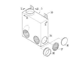
Fig. 4 is a perspective exploded view of the present
invention;
Fig. 5 is a sectional view taken along line V-V of Fig. 4;
Fig. 6 is a sectional view taken along line VI-VI of Fig.
4;
Fig. 7 is a perspective view of a first embodiment of the

present invention;
Fig. 8 is a sectional view taken along line VIII-VIII of
Fig. 7i
Fig. 9 is a side view of a second embodiment of the
present invention;
Fig. lO is a side view of a third embodiment of the
present invention;
Fig. ll is a perspective view of a fourth embodiment of
the present invention;

CA 02211818 1997-07-30

.


Fig. 12 shows a fifth embodiment of the present invention;
Fig. 13 is a perspective view of a sixth embodiment of
the present invention;
Fig. 14 is a perspective view of a seventh embodiment of
the present invention;
Fig. 15 is a view according to Fig. 14, wherein the
housings are separated from the funnel;
Fig. 16 shows an eighth embodiment of the present
lnventlon;
Fig. 17 is view according to Fig. 16, wherein the housing
is separated from the- funnel; and Fig. 18 shows a
ninth embodiment of the present invention.

DETAILED DESCRIPTION OF THE PREFERRED EMBODIMENTS
Please refer to Figs. 4 to 6. The present invention
includes a housing 3 partitioned into two internal rooms.
One of the rooms is a bellows 31 for creating pressure,
while the other is a guide box 32 for guiding the smoke.
The bellows 31 has an entrance 311 communicated with the
guide box 32 and an exit 312 communicated with outer side
of the housing 3. A fan 313 driven by a motor 33 is
disposed in the bellows 31. The bottom of the bellows 31
is disposed with an oil draining opening 314. The guide
box 32 surrounds a front side 315, right side 316, left
side 317 and a bottom face 318 of the bellows 31 and is


. . ._~,

CA 022ll8l8 l997-07-30


spaced from the bellows 31 to define a path for air flow
to smoothly pass therethrough. Each of the three sides
315, 316, 317 iS disposed with a sucking mouth 34 on the
corner, which is communicated with the entrance 311. The
bottom of the housing 3 iS formed with a downward
inclined oil guiding section 35 having an oil outlet 351
at bottom end.


The sucking mouth 34 of the housing 3 can be e~uipped
with a mesh 37 or a cover member 36 for sealing the
sucking mouth 34. Also, the sucking mouth 34 can be
connected with other pipe member by a connector 38. The
top end of the housing 3 iS disposed with two hanging
hooks 39.

Referring to Figs. 7 and 8, when applied as a smoke
exhausting device in kitchen, the present invention is
used with a smoke collecting funnel 4. The top end of the
funnel 4 iS disposed with a movable cover board 44. The
interior of the funnel is formed as a smoke collecting
chamber 41. A locating seat 42 iS disposed on rear side
of the chamber 41 and an oil cup 43 iS disposed at bottom
end of the funnel 4.


In use, the funnel 4 is first fixed at a desired

CA 02211818 1997-07-30


position. Then two housings 3 are respectively fixed on
the locating seat 42 of the funnel 4 and connected with a
ventilation pipe (not shown) which is conducted outside
the wall. When smoke is produced during coo~ing, the fan
313 is driven by the motor 33 to rotate and create a
sucking force, whereby the smoke is sucked from the
sucking mouth 34 into the guide box 32 and then sucked
from the entrance 311 into the bellows 31. The smoke in
the bellows 31 is forced to inner side thereof to
condense into oil drops. The oil drops flow from the oil
draining opening 314 to the oil guiding section 35 of the
guide box 32 and flow from the oil exit 351 into the oil
cup 43. A mesh 37 can be disposed at the sucking mouth 34
for filtering the oil and protecting the fan 313.

Referring to Fig. 9, according to a second embodiment
of the present invention, the housing 5 is installed on
outer side of the wall 51 and the funnel 52 and the
housing 5 are connected by a ventilation pipe 53.

Referring to Fig. 10, according to a third embodiment
of the present invention, a filtering mesh 56 is disposed
on bottom face of the funnel 55 and a filter 59 with
activated carbon is disposed in the guide box 58.


CA 02211818 1997-07-30


Fig. 11 shows a fourth embodiment of the present
invention, in which the housing 6 ls separated from the
funnel 61 and installed outside the kitchen cabinet 62.
The housing 6 is connected with the funnel 61 by a
ventilation pipe 63. Accordingly, the ventilation pipe 63
will not occupy the space of the kitchen cabinet 62.


Fig. 12 shows a fifth embodiment of the present
invention, in which in the case that there is a quite
long distance between the housing 65 and outer side of
the room and the ventilation pipe 66 is bent or too long
so that a high resistance is created in the ventilation
pipe 66, over two housings 65 can be installed at the
middle or the end of the smoke path to increase the smoke
exhausting force. The additional sucking mouth 67 of the
housing 65 can be sealed by a cover body 68 to avoid
leakage of smoke.


; Fig. 13 shows a sixth embodiment of the present
invention, in which the funnel 7 has a thinner pattern
and the housing 71 protrudes beyond the top end of the
funnel 7. Such housing 71 is applicable to a thick or a
thin funnel 7.


Fig. 14 shows a seventh embodiment of the present

CA 02211818 1997-07-30


invention, which is applicable to a kitchen of a
restaurant. The funnel 75 is wider so that more housings
76 are installed on the funnel 75 side by side for
sucking smoke covering a larger area. Similar to Fig. 15,
in use, the housings 77 can be separated from the funnel
78.


Fig. 16 shows an eighth embodiment of the present
invention, in which one side of the funnel 8 is disposed
with a smoke discharging opening 81 and the exit 821 of
the housing 82 is disposed on the same side, whereby the
collected smoke is discharged from one side. This will
not affect the smoke exhausting effect. Also, the cabinet
83 is free from the ventilation pipe 84 so that more
space of the cabinet 83 is saved for use.


Referring to Fig. 17, in the above embodiment, the
housing 85 is separated from the funnel 87 and installed
on the wall 88 with the exit 851 disposed on one side
thereof.


Fig. 18 shows a ninth embodiment of the present

invention, in which the housing 9 is solely used in a
bar-be-cue restaurant or directly installed beside a bar-

be-cue oven 91. The sucking mouth 92 directly sucks the


..

CA 02211818 1997-07-30


smoke produced from the oven 91. The oil drop is
collected by the oil cup 93 at the bottom of the
housing 9.

It is to be understood that the above description and
drawings are only used for illustrating some embodiments
of the present invention, not intended to limit the scope
thereof. Any variation and derivation from the above
description and drawings should be included in the scope
of the present invention.

Representative Drawing
A single figure which represents the drawing illustrating the invention.
Administrative Status

For a clearer understanding of the status of the application/patent presented on this page, the site Disclaimer , as well as the definitions for Patent , Administrative Status , Maintenance Fee  and Payment History  should be consulted.

Administrative Status

Title Date
Forecasted Issue Date 2003-03-25
(22) Filed 1997-07-30
(41) Open to Public Inspection 1999-01-30
Examination Requested 1999-04-07
(45) Issued 2003-03-25
Deemed Expired 2005-08-01

Abandonment History

There is no abandonment history.

Payment History

Fee Type Anniversary Year Due Date Amount Paid Paid Date
Application Fee $150.00 1997-07-30
Request for Examination $200.00 1999-04-07
Maintenance Fee - Application - New Act 2 1999-07-30 $50.00 1999-07-06
Maintenance Fee - Application - New Act 3 2000-07-31 $50.00 2000-06-14
Maintenance Fee - Application - New Act 4 2001-07-30 $100.00 2001-05-30
Maintenance Fee - Application - New Act 5 2002-07-30 $150.00 2002-05-19
Final Fee $300.00 2003-01-09
Maintenance Fee - Patent - New Act 6 2003-07-30 $150.00 2003-06-04
Owners on Record

Note: Records showing the ownership history in alphabetical order.

Current Owners on Record
CHANG, LI -LIN
Past Owners on Record
None
Past Owners that do not appear in the "Owners on Record" listing will appear in other documentation within the application.
Documents

To view selected files, please enter reCAPTCHA code :


To view images, click a link in the Document Description column. To download the documents, select one or more checkboxes in the first column and then click the "Download Selected in PDF format (Zip Archive)" or the "Download Selected as Single PDF" button.

List of published and non-published patent-specific documents on the CPD .

If you have any difficulty accessing content, you can call the Client Service Centre at 1-866-997-1936 or send them an e-mail at CIPO Client Service Centre.


Document
Description 
Date
(yyyy-mm-dd) 
Number of pages   Size of Image (KB) 
Cover Page 2003-02-18 1 39
Cover Page 1999-02-25 1 55
Abstract 1997-07-30 1 27
Description 1997-07-30 9 248
Claims 1997-07-30 3 63
Drawings 1997-07-30 15 218
Representative Drawing 1999-02-25 1 7
Assignment 1997-07-30 3 124
Correspondence 2003-01-09 1 34
Prosecution-Amendment 1999-04-07 2 55
Correspondence 2000-06-14 1 25