Note: Descriptions are shown in the official language in which they were submitted.
CA 0221198~ 1998-07-10
DEVICE AND METHOD FOR BREAKING
A GLASS VIAL CONTAINING INJECTIBLE
LIQUID SOLUTIONS
BACKGROUND OF THE INVENTION
1. Field of the Invention
This invention relates to a device and method for breaking multi-
si~ed glass vials and enabling liquid contents to be safely drawn
out. The attributes of the device and the method for utilizing the
device minimize the manual handling of the vial in the process of
drawing out liquid subcutaneous, intramuscular or intravenous
medications and other liquid solutions, thereby negating the risk of
contamination or infection associated with exposure to the liquid
agent and the risk of injury caused by glass shards in breaking the
vial by manual handling.
2. Description of Related Art
In administering liquid subcutaneous, intramuscular or intravenous
medications, pharmaceuticals and biologicals and other liquid
solutions by syringe injection, a concern exists as to contamination,
infection and injury to the person administering the injection.
Prior art devices exist for the purpose of breaking ampoules in an
apparatus for collecting and transporting biological specimens. A
typical collecting and transporting device has been patented as
United States Patent No. 4,014,748. An improvement of this art was
claimed in a device granted Canadian Patent No. 2,110,834.
Characteristic of the existing devices in the art is the collection
and transportation of biological specimens contained in ampoules
that can be broken in a container in order to release liquid medium.
The aim of such devices is to substantially prevent the specimen
collected in the apparatus from being exposed to the outside
environment.
Distinct from such devices which have as their aim the collection
and transportation of biological specimens in ampoules, the purpose
of the present invention is to ensure a safe and effectual means of
administering injectible liquids contained in vials. The subject
device and method is suitable for application to single-use glass
CA 0221198~ 1998-07-10
vials or ampoules which require breakage of the glass in order to
effect the administering of the contents.
SUMMARY OF THE INVENTION
The present invention is a device and method for breaking glass
vials containing liquid substances for subcutaneous, intramuscular
or intravenous injection by syringe. In particular, the device may
be used as an apparatus to safeguard human contact from hazardous
liquids and glass shards deriving from the breaking of the vial, and
further to minimize the risk of human contact and exposure to
harmful bacteria in the environment while engaged in the process of
administering injections of the liquid substances. More specifically,
the device facilitates a method for minimizing contamination of the
liquid substance, needle pricking of the person administering the
injection, wastage of the liquid substance caused by shattering of
the glass vial, and bacteriological or other infection caused by
contact with the skin.
The device and method are suitable for application in the
administering of liquid substances by injection in a broad context,
including medical, veterinary and laboratory uses among others. It
is appropriate for use in hospital, clinic and nursing home settings
among others.
The device is preferably an apparatus in which the subject glass
vial is placed and held in the appropriate sized cavity. A second
apparatus in the nature of a cylinder and plunger is secured manually
onto the top portion of the vial. With a twisting motion the neck
of the vial is cleanly broken. The top portion of the vial is
thereby held in the cylinder while the vial base with liquid contents
remains in the holder apparatus.
The syringe with capped needle is placed in the appropriately sized
slot in the holder apparatus, which secures the syringe in a fixed
position. As the needle cap is held in place, the syringe and
needle are withdrawn manually by a twisting motion with upward
force.
The needle of the syringe is then inserted into the opened vial
which remains held in place by the apparatus. The vial contents
CA 0221198~ 1998-07-10
are drawn out of the vial and into the syringe where it is now
capable of being administered by injection.
The button at the top of the plunger in the cylinder apparatus is
depressed, releasing the cap of the broken vial for disposal. The
cylinder apparatus is then replaced into its storage location on
the holder apparatus, ready for the next usage.
The final step is to manually depress the lever handle on the holder
apparatus which partially ejects the lower portion of the vial from
the machine, enabling the operator to dispose of the empty vial.
By virtue of the preferable forms of each apparatus of the device
and the method undertaken in the process, human contact with the
needle, the glass vial and the vial contents is minimized, thereby
diminishing the potential for exposure to hazardous chemicals,
biologicals, pharmaceuticals and other liquids and the exposure to
needle pricking and broken glass. Additionally the device and
method minimize the potential for unintended release of the liquid
contents of the vial by spillage and minimize the wastage of the
liquid by inefficient breakage.
CA 0221198~ 1998-07-10
DESCRIPTION OF THE DRAI~INGS
Fig. 1 shows two perspectives of the holder apparatus illustrating
the manual placing of the glass vial in the apparatus and the manner
in which the vial is held in place in a correct sized, slightly
angled cavity in the apparatus.
E'ig. 2 illustrates a perspective of the manual placing of the
cylinder apparatus onto the top of the glass vial and a perspective
of the internal attachment of the cylinder and plunger apparatus
onto the top of the vial which is secured in the holder apparatus.
Fig. 3 illustrates the manual twisting motion exerted on the cylinder
apparatus in order to cleanly break the neck of the glass vial while
the bottom portion of the vial is fixed in place. A second
perspective shows an internal view of the severed vial top held in
the cylinder.
Fig. 4 illustrates the placing of the needle-capp~ syringe into the
appropriate slot of the holder apparatus where it is secured in place.
A second perspective shows an internal view of the needle-capped
syringe and the open-topped vial held in place in their respective
slots in the holder apparatus.
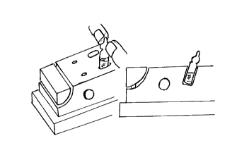
Fig. 5 illustrates the release and withdrawal of the syringe from
the ~older apparatus by depressing the release button on the side
of the holder. A second internal perspe~tive shows the needle cap
and the open-topped vial secured in place.
Fig. 6 illustrates the manual insertion of the needle of the syringe
into the open-topped vial to facilitate the drawing out of the
liquid contents of the vial. A second perspective shows an internal
view of the holder as the syringe withdraws the vial contents.
Fig. 7 illustrates how the liquid is drawn out of the vial and into
the syringe by holding the body of the syringe with one hand while
the syringe's plunger is slowly raised with the other hand. A
second internal perspective of the holder shows the liquid contents
now transferred from the vial to the syringe.
Fig. 8 illustrates the syringe being replaced into the holder
apparatus after usage, where it is reinserted into the se-~r~d needle
cap. A second internal view of the holder shows the reintegrated
CA 0221198~ 1998-07-10
syringe and needle cap held in place.
Fig. 9 illustrates the manual depressing of the ejector lever
handle on the holder apparatus such that the bottom portion of the
vial is partially ejected. A second internal view of the holder
shows the partial ejection of the vial from the holder apparatus,
ready for removal and disposal.
Fig. 10 illustrates the manual depressing of the button on the top
of the plunger shaft of the cylinder apparatus, thereby releasing
the severed top of the vial for disposal. A second partial internal
view of the cylinder shows the ejection of the vial cap.
Fig. 11 is a depiction of the device showing the holder apparatus (1)
with four cylinders stored in place at the side (2a-d). The drawing
depicts the ejector handle (3), the needle cap lock shaft release
button (4), two slots for holding syringe needle caps of different
sizes (5a-b), and five double rows of cavities to accommodate the
insertion of multi-sized vials (6a-e).
Fig. 12 is an internal view of the holder apparatus depicting five
multi-sized cavities for holding the vials (6a-e), ejector handle (3),
needle cap lock shaft (7), return spring (8), lever (9), axle (10),
mounted dowel (11), peg board (12) and base screws (13a-b).
Fig. 13 is a depiction of the various constituent parts of the
holder apparatus. Shown are the needle cap lock shaft (7), needle
cap lock shaft release button (4), lever (9), mounted dowels of the
ejector handle (11), return spring (8), axle (10) with axle shaft (14)
and axle shaft retainer lock (15), peg board (12) and base screws
(13a-b).
Fig. 14 illustrates four sizes of the cylinder apparatus, each from
an external and internal perspectives. The top row shows the outer
casing of the cylinders (16a-d) and plunger release b~tton (17) on each.
The lower row depicts the plunger shaft (18) of each cylinder, the
'o'-ring inside each cylinder (19) and multi-sized apertures at the
base of each cylinder, fitted for various standard vial sizes (20a-d).
As shown in Fig.12, the vial-sized cavities i~ the hold~r apparatus
are preferably angled at about ten degrees (10~) from vertical to
allow the maximum liquid to be drawn out from the vial, which often
has a concave base.
CA 0221198~ 1998-07-10
While this invention is satisfied by embodiments in may different
fo~ms, the drawings depicted herein and described in detail
illustrate the pr~ferred embodiments of the invention. It is
understood that this disclosure is to be considered exemplary of the
principles of the invention and is not intended to limit the
invention to the embo~iments depicted. Various other modifications
will be apparent to and readily made by those skilled in the art
without departing from the scop and spirit of the invention. The
scope of the invention will be measured by t'ne app~nded claims and
their equivalents.