Language selection

Search

Patent 2212119 Summary

Third-party information liability

Some of the information on this Web page has been provided by external sources. The Government of Canada is not responsible for the accuracy, reliability or currency of the information supplied by external sources. Users wishing to rely upon this information should consult directly with the source of the information. Content provided by external sources is not subject to official languages, privacy and accessibility requirements.

Claims and Abstract availability

Any discrepancies in the text and image of the Claims and Abstract are due to differing posting times. Text of the Claims and Abstract are posted:

  • At the time the application is open to public inspection;
  • At the time of issue of the patent (grant).
(12) Patent Application: (11) CA 2212119
(54) English Title: BACKHOE DIPPERSTICK
(54) French Title: BRAS DE GODET D'UNE PELLE RETROCAVEUSE
Status: Deemed Abandoned and Beyond the Period of Reinstatement - Pending Response to Notice of Disregarded Communication
Bibliographic Data
(51) International Patent Classification (IPC):
  • E02F 3/32 (2006.01)
  • E02F 3/38 (2006.01)
(72) Inventors :
  • HENDRON, SCOTT SVEND (United States of America)
  • MCMULLEN, LARRY GENE (United States of America)
(73) Owners :
  • DEERE & COMPANY
(71) Applicants :
  • DEERE & COMPANY (United States of America)
(74) Agent: BORDEN LADNER GERVAIS LLP
(74) Associate agent:
(45) Issued:
(22) Filed Date: 1997-08-21
(41) Open to Public Inspection: 1998-05-19
Examination requested: 1997-08-21
Availability of licence: N/A
Dedicated to the Public: N/A
(25) Language of filing: English

Patent Cooperation Treaty (PCT): No

(30) Application Priority Data:
Application No. Country/Territory Date
08/751,802 (United States of America) 1996-11-19

Abstracts

English Abstract


A backhoe dipperstick is provided with a second end adjacent to the bucket.
The dipperstick comprises a box beam having a front wall, a back wall and two
sidewalls interconnecting the front and back walls. At the second end the sidewalls
extend past the front wall towards the curled bucket. These extensions are provided
with gripping teeth. The gripping teeth therefore are an integral feature of thedipperstick.


French Abstract

Bras de godet d'une pelle rétrocaveuse comportant une seconde extrémité près du godet. Le bras comprend une poutre caisson présentant une paroi avant, une paroi arrière et deux parois latérales interreliant les parois avant et arrière. € la seconde extrémité, les parois latérales se prolongent au-delà de la paroi avant vers le godet replié. Ces prolongements sont munis de dents de préhension qui constituent donc une caractéristique intégrale du bras de godet.

Claims

Note: Claims are shown in the official language in which they were submitted.

The embodiments of the invention in which an exclusive property or privilege
is claimed are defined as follows:
1. A work vehicle for performing a work operation, the work vehicle
comprising:
a frame;
ground engaging means are coupled to the frame for supporting the
propelling the frame;
a boom is pivotally coupled to the frame;
a dipperstick having a first end being pivotally coupled to the boom, the
dipperstick also having a second end that is pivotally coupled to a bucket. The
dipperstick being a box beam having a front wall, a back wall and two sidewalls
interconnecting the front and back walls, the sidewalls located at the second end of
the dipperstick adjacent to the bucket extend past the front wall and are provided
with gripping teeth that are integral with the dipperstick.
2. A work vehicle as defined by claim 1 wherein the bucket is provided with
curved side edges.
3. A work vehicle as defined by claim 2 wherein the dipperstick is an
extendible dipperstick having a sleeve portion including the first end and an insert
portion including the second end.
4. A work vehicle for performing a work operation, the work vehicle
comprising:
a frame;
ground engaging means are coupled to the frame for supporting the
propelling the frame;
a boom is pivotally coupled to the frame;
an extendible dipperstick having a sleeve portion and an insert portion the
sleeve portion including a first end being pivotally coupled to the boom, the insert
portion including a second end that is pivotally coupled to a bucket. The dipperstick
being a box beam having a front wall, a back wall and two sidewalls interconnecting
the front and back walls, the sidewalls located at the second end of the dipperstick
adjacent to the bucket extend past the front wall and are provided with gripping teeth
that are integral with the dipperstick.

Description

Note: Descriptions are shown in the official language in which they were submitted.


CA 022l2ll9 l997-08-2l
BACKHOE DIPPERSTICK
BACKGROUND OF THE INVENTION
1. Field of the invention:
The invention is directed to providing an improved dipperstick for a backhoe
having integral gripping teeth adjacent to the bucket for gripping logs and other
material clamped against the dipperstick by the curled bucket.
2. Description of the Prior Art:
Excavators such as backhoes, are work vehicles used for a variety of jobs.
An excavator is provided with a pivotal boom to which is attached a pivotal
dipperstick. The positions of the boom relative to the vehicle and the dipperstick
relative to the boom are controlled by hydraulic cylinders. A bucket is pivotally
attached to the end of the dipperstick remote from the boom. A hydraulic cylinder
pivotally attached to the dipperstick is used to position the bucket relative to the
dipperstick through a bucket linkage.
Backhoes maybe used to lift logs and other material. Sometimes the bucket
is provided with a thumb for holding material trapped by the dipperstick. In addition
the bucket maybe provided with gripping teeth. It is also known that users have
welded plates to the dipperstick and bucket. These plates can be provided with
gripping teeth.
SUMMARY
It is an object of the present invention to provide an improved dipperstick for a
backhoe having integral gripping teeth located adjacent to the bucket for gripping
logs and other material clamped against the dipperstick by the curled bucket.
The dipperstick of the backhoe has a first end pivotally coupled to the
backhoe boom and a second opposite end pivotally coupled to the bucket. The
dipperstick comprises an integral box beam having a front wall a back wall and two
sidewalls located between the front and back walls. The sidewalls adjacent to the
second end are provided with integral extensions that extend toward the curled
3 o bucket. The integral extensions are provided with gripping teeth for gripping objects
trapped by the curled bucket.
BRIEF DESCRIPTION OF THE DRAWINGS
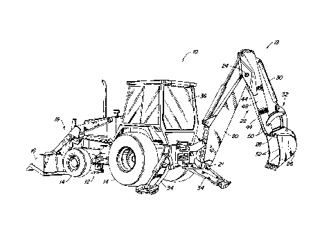
Figure 1 is a perspective view of a backhoe loader.

CA 022l2ll9 l997-08-2l
Figure 2 is a side view of the bucket linkage in a curled position.
DETAILED DESCRIPTION
Fig. 1 illustrates a work vehicle, such as a backhoe loader 10, having a frame
12 to which are mounted ground engaging means 14 for supporting and propelling
the frame. The backhoe loader is provided with a loader bucket 16 having a suitable
loader bucket linkage 18 for manipulating the loader bucket relative to the frame.
The rear of the backhoe loader is provided with a backhoe having a boom 20 that is
pivotally coupled to the frame at pivot 21, a dipperstick 22 that is pivotally connected
to the boom at pivot 24 and a bucket 26 that is pivotally connected to the dipperstick
22 at pivot 28. A bucket actuating hydraulic cylinder 30 manipulates the bucket 26
through a bucket linkage 32. The backhoe loader is also provided with two
stabilizers 34. The operation of the vehicle is controlled from operator's cab 36.
The dipperstick 22 illustrated in Fig.1 is an extendible dipperstick. The
extendible dipperstick comprises a sleeve portion 37 receiving an insert portion 38.
15 The sleeve portion 37 includes the first end 40 of the dipperstick 22 which is pivotally
coupled to the backhoe boom 20. The insert portion includes the second end 42
which is pivotally coupled to the bucket 26. It should be noted that the presentinvention could also be applied to a non-extendible dipperstick. The description of
the dipperstick below can apply equally to an extendible or a non-extendible
dipperstick.
The dipperstick comprises a box beam having a front wall 44, a backwall 46
and two sidewalls 48 interconnecting the front and back walls 44 and 46. At the
second end 42 of the dipperstick 22 adjacent to the bucket 26 the sidewalls 48
extend past the front wall 44 a short distance and are provided with integral gripping
teeth 50. It should be noted that the bucket 26 is provided with curved side edges
52 adding to the gripping force of the bucket 26 and the dipperstick 22.
In a work operation an operator may want to lift an object such as a log L. To
grip the log L the operator manipulates the bucket and dipperstick so that the bucket
curls and forces the log against the gripping teeth. The dipperstick and the boom
30 can then be manipulated to manipulate the log as it is trapped by the curled bucket.
To release the log the bucket is uncurled

CA 02212119 1997-08-21
The present invention should not be limited by the above described
embodiment, but should be limited solely by the claims that follow.

Representative Drawing
A single figure which represents the drawing illustrating the invention.
Administrative Status

2024-08-01:As part of the Next Generation Patents (NGP) transition, the Canadian Patents Database (CPD) now contains a more detailed Event History, which replicates the Event Log of our new back-office solution.

Please note that "Inactive:" events refers to events no longer in use in our new back-office solution.

For a clearer understanding of the status of the application/patent presented on this page, the site Disclaimer , as well as the definitions for Patent , Event History , Maintenance Fee  and Payment History  should be consulted.

Event History

Description Date
Application Not Reinstated by Deadline 2000-08-21
Time Limit for Reversal Expired 2000-08-21
Deemed Abandoned - Failure to Respond to Maintenance Fee Notice 1999-08-23
Application Published (Open to Public Inspection) 1998-05-19
Inactive: First IPC assigned 1997-10-29
Inactive: IPC assigned 1997-10-29
Classification Modified 1997-10-29
Inactive: Filing certificate - RFE (English) 1997-10-14
Filing Requirements Determined Compliant 1997-10-14
Application Received - Regular National 1997-10-09
Letter Sent 1997-10-09
Request for Examination Requirements Determined Compliant 1997-08-21
All Requirements for Examination Determined Compliant 1997-08-21

Abandonment History

Abandonment Date Reason Reinstatement Date
1999-08-23

Fee History

Fee Type Anniversary Year Due Date Paid Date
Application fee - standard 1997-08-21
Request for examination - standard 1997-08-21
Registration of a document 1997-08-21
Owners on Record

Note: Records showing the ownership history in alphabetical order.

Current Owners on Record
DEERE & COMPANY
Past Owners on Record
LARRY GENE MCMULLEN
SCOTT SVEND HENDRON
Past Owners that do not appear in the "Owners on Record" listing will appear in other documentation within the application.
Documents

To view selected files, please enter reCAPTCHA code :


To view images, click a link in the Document Description column. To download the documents, select one or more checkboxes in the first column and then click the "Download Selected in PDF format (Zip Archive)" or the "Download Selected as Single PDF" button.

List of published and non-published patent-specific documents on the CPD .

If you have any difficulty accessing content, you can call the Client Service Centre at 1-866-997-1936 or send them an e-mail at CIPO Client Service Centre.


Document
Description 
Date
(yyyy-mm-dd) 
Number of pages   Size of Image (KB) 
Abstract 1997-08-21 1 11
Description 1997-08-21 3 105
Claims 1997-08-21 1 42
Drawings 1997-08-21 2 68
Cover Page 1998-05-29 1 51
Representative drawing 1998-05-29 1 21
Courtesy - Certificate of registration (related document(s)) 1997-10-09 1 116
Filing Certificate (English) 1997-10-14 1 164
Reminder of maintenance fee due 1999-04-22 1 111
Courtesy - Abandonment Letter (Maintenance Fee) 1999-09-20 1 187