Note: Descriptions are shown in the official language in which they were submitted.
CA 02212273 1997-08-O1
BI-3226
SCINTILLATION DETECTOR WITH SLEEVED. CRYSTAL BOOT
FIELD OF THE INVENTION
The invention herein described relates generally to a
scintillation detector and method for performing radiation-
based measurements, and to a method of manufacturing a
scintillation detector. The scintillation detector and
method are particularly useful for borehole logging
applications, but may, however, have use in other
l0 applications, particularly those plagued by vibration
induced counts intermixed with radiation induced counts.
BACKGROUND OF THE INVENTION
Scintillation detectors have been employed in the oil
and gas industry .for well logging. These detectors have
used thallium activated sodium iodide crystals that are
effective in detecting gamma rays. The crystals are
enclosed in tubes or casings to form a crystal package.
The crystal package has an optical window at one end of the
casing which permits radiation induced scintillation light
to pass out of the crystal package for measurement by a
light sensing device such as a photomultiplier tube coupled
to the crystal package. The photomultiplier tube converts
the light photons emitted from the crystal into electrical
pulses that are shaped and digitized by associated
electronics. Pulses that exceed a threshold level are
registered as counts that may be transmitted "uphole" to
analyzing equipment or stored locally.
The ability to detect gamma rays makes it possible to
analyze rock strata surrounding the bore holes, as by
measuring the gamma rays coming from naturally occurring
radioisotopes in down-hole shales which bound hydrocarbon
reservoirs. Today, a common practice is to make
CA 02212273 1997-08-O1
BI-3226
measurements while drilling (MWD). For MWD applications,
the detector must be capable of withstanding high
temperatures and also must have high shock resistance. At
the same time, there is a need to maintain performance
specifications. '
A problem associated with MWD applications is that the
detector will report a higher than an actual count rate if
the scintillation crystal package produces vibration
l0 induced light pulses. The harsh shock and vibration
conditions the detectors encounter during drilling can
cause a crystal package to emit spurious light pulses in
addition to gamma ray induced light pulses. That is, the
detector output will be composed of radiation induced
counts and vibration induced counts. Heretofore, the
detector electronics could not distinguish the vibration
induced counts from the genuine gamma counts, whereby the
detector reports a higher than actual count rate. The
problem is more severe when detecting low level radiation
events while the detector is being subjected to a very
severe dynamic operational environment.
Some prior art electronic solutions have attempted to
filter out vibration induced counts by discriminating on
the basis of the pulse shape and/or the signal decay time.
These techniques, however, have proven unreliable.
SUMMARY OF THE INVENTION
The present invention provides a "hardware" solution
to the aforesaid problem. According to one primary aspect
of the invention, components of a radiation detector
assembly are rigidified or stiffened to move the resonant
2
CA 02212273 1997-08-O1
BI-3226
frequencies of vibration induced counts from the detector
assembly above a threshold frequency (i.e., the upper limit
of the operational dynamic disturbance bandwidth). This is
accomplished by loading the scintillation crystal both
axially and radially such that the several different
scintillator rigid body resonant frequencies are above the
threshold frequency. Thus, the crystal is loaded within a
housing to provide sufficient stiffness such that the
operational dynamic bandwidth of the detector application
to falls below the resonant frequency of vibration induced
counts. Therefore, within that environment, vibration
induced counts will either not occur or will have a
magnitude that falls below an amplitude threshold and will
therefore be ignored.
According to a preferred embodiment of the invention,
axial loading of the scintillation crystal may be effected
in a well known or other suitable manner, while radial
loading is accomplished through the novel use of a sleeve
split along its axial length such that it can be radially
expanded and contracted around a resiliently compressible
boot or other shock absorbing member circumscribing the
scintillation crystal. The split sleeve is assembled
around the boot and scintillation crystal to form a
subassembly insertable into a housing, such as a tube or
casing preferably made of metal. The housing is internally
dimensioned such that the boot is maintained in radial
compression for application of a radial compression load on
the scintillation crystal. As will be appreciated, the
wall thickness of the split sleeve may be selected as
desired to provide a predetermined amount of radial loading
and thus stiffness. The radial stiffness, along with the
axial stiffness, may be selected to impart sufficient
3
CA 02212273 1997-08-O1
BI-3226
rigidity to the detector assembly such that the several
different resonant frequencies associated with different
vibration modes of the detector assembly, which will
produce vibration induced counts if excited, will occur
above the operational threshold frequency for the given
application.
The sleeve preferably is made of metal having a
coefficient of friction with the housing that is
l0 substantially less than the coefficient of friction between
the resiliently compressible boot and a housing for the
scintillation crystal and boot, thereby providing for
reduced frictional resistance during insertion of the
crystal/boot/split sleeve subassembly into the housing,
which is internally dimensioned less than the unloaded
radial dimension of the subassembly. The split sleeve
preferably has sufficient stiffness or rigidity to enable
compression of the boot over an axial extent thereof
extending axially beyond the location at which the sleeve
is compressed by a compression ring, clamp or other
suitable member used to facilitate insertion of the
crystal, boot and sleeve subassembly into the housing.
Accordingly, an end of the subassembly may be radially
compressed by the compression ring surrounding the split
sleeve at a point spaced from such end so as to permit
insertion of such. end into the housing with less force than
would be necessary without the split ring while still
providing the desired radial loading.
3o Thus, the present invention additionally provides an
improved method of assembling a detector assembly. The
improved method enables the manufacture of a detector
assembly with a radial loading of the scintillation crystal
4
CA 02212273 1997-08-O1
BI-3226
substantially greater than that heretofore provided in
similar detector assemblies. In addition, the improved
method employing a split sleeve can be used to facilitate
manufacture of detector assemblies regardless of the extent
of radial loading.
Therefore, according to the invention, a scintillation
detector comprises a scintillation crystal, a resiliently
compressed shock absorbing member circumscribing the
l0 crystal, a sleeve circumscribing the shock absorbing
member, and a housing having a casing wall circumscribing
the sleeve. A reflector may be interposed between the
crystal and shock absorbing member to provide optimal
collection of radiation induced counts. The sleeve may
also have a longitudinally extending gap,in the wall
thereof to provide for radial compression, thereby
providing for substantial, uniform and controlled radial
loading on the crystal.
2o According to another aspect of the invention, a
scintillation detector comprises a scintillation detector
subassembly including a scintillation crystal, a
resiliently compressed protection means around the crystal,
and compressing means around the compressed protection
means. A housing circumscribes the subassembly such that
the subassembly remains in a compressed state, thereby
providing uniform, controlled radial loading on the
crystal.
3o According to yet another aspect of the invention, a
method of manufacturing a scintillation detector includes
placing a scintillation crystal within a resiliently
compressible shock absorbing member and placing the shock
5
CA 02212273 1997-08-O1
BI-3226
absorbing member in a sleeve. The sleeve and shock
absorbing member are radially compressed and inserted into
a housing which substantially maintains the radial
compression, thereby achieving an interference fit between
the sleeve and th.e housing and controlled uniform radial
loading along the crystal.
According to a further aspect of the invention, a
method of measuring radiation includes the steps of using a
l0 scintillation detector having a scintillation crystal
loaded within a scintillation crystal housing such that the
stiffness on the crystal is sufficiently great such that
any vibration induced counts of sufficient amplitude to be
recorded as an event occur above a threshold frequency,
i.e., above the upper limit of the operational dynamic
disturbance bandwidth to which the detector is exposed
during radiation measurement. That is, the detector is
used in an environment that has a dynamic bandwidth below
the threshold frequency, thereby substantially eliminating
vibration induced counts in radiation based measurements.
According to a still further aspect of the invention,
a method for making radiation based measurements in a high
vibration environment includes positioning a scintillation
detector having a scintillation crystal in a high vibration
environment for interaction with incident radiation,
wherein the scintillation crystal has sufficient stiffness
such that vibration induced and recordable photons are not
excited by the crystal's environmental dynamic conditions.
A light sensing device receives emitted photons from the
scintillation crystal and converts the photons into
electrical signals, wherein the electrical signals
substantially represent the radiation being measured.
6
CA 02212273 1997-08-O1
BI-3226
The invention comprises the foregoing and other
features hereinafter fully described and particularly
pointed out in the claims, the following description and
the annexed drawings setting forth in detail a certain
illustrative embodiment of the invention, this being
indicative, however, of one of the various ways in which
the principles of the invention may be employed.
BRIEF DESCRIPTION OF THE DRAWINGS
In the annexed drawings:
Figure 1 is a fragmentary longitudinal sectional view
of a scintillation detector according to the invention;
Figure 2 is an exploded view of components of the
scintillation detector according to the invention; and
Figure 3 is a perspective diagram illustrating a
scintillation detector subassembly being compressed and
inserted into a housing.
DETAILED DESCRIPTION OF THE INVENTION
The problem of vibration induced counts associated
with MWD applications is solved by appreciating that
vibration induced counts are a function of the dynamic
rigid body vibration modes of the crystal. By increasing
the axial and radial stiffness on the crystal within the
detector, the frequency of excitation needed to effect
recordable vibration induced counts is also increased. In
the past, high axial loading could be relatively easily
accomplished. However, it was difficult, if not
impossible, to attain the necessary radial loading using
known assembly techniques. The radial dimension of the
CA 02212273 1997-08-O1
BI-3226
uncompressed subassembly needed to attain such high radial
loads would be such that attempts to insert the subassembly
into the housing would not be possible or would cause
damage to the boot. According to the present invention,
high radial loading can be accomplished by placing the boot
and crystal into a sleeve which is then radially compressed
and inserted into the detector housing. The frictional
force between the sleeve and housing is substantially less
than that between the boot and housing, thereby allowing a
l0 greater radial loading to be accomplished during assembly
without damage to the boot. The increased radial stiffness
causes vibration .induced counts to occur'at higher
excitation frequencies, such as at frequencies above a
threshold frequency, i.e., above the operational dynamic
bandwidth of the detector. Accordingly, the detector will
not be exposed to frequencies high enough to excite the
vibratory modes of the detector assembly, whereby the
detector will not produce vibration induced counts.
Further, to the extent some white noise is present in an
2o MWD application, the magnitude of any vibration induced
counts are not sufficiently large to be tallied as a count,
i.e, are not of sufficient amplitude to be counted as a
recordable event.
The present invention provides an improved
scintillation detector assembly having a~scintillation
crystal circumscribed by a resiliently compressible shock
absorbing member. A sleeve circumscribes the shock
absorbing member and is compressible or deformable to
3o thereby apply a substantial radial loading on the crystal
that is uniform and controllable. The compressed or
deformed sleeve is circumscribed by a casing wall of a
housing that substantially maintains the radial loading on
8
CA 02212273 1997-08-O1
BI-3226
the crystal. The stiffness imparted to~the detector
assembly is sufficient to not cause vibration induced
photon emissions in the intended operational excitation
bandwidth, thereby eliminating vibration induced counts in
radiation based measurements.
The sleeve may be composed of a material that has a
substantially lower coefficient of friction with the
housing than the shock absorbing member, thereby allowing a
to greater radial loading to be achieved on the crystal due to
the reduced frictional forces encountered during insertion
of the crystal into a housing. Further, the sleeve may
have a longitudinal gap to readily provide for radial
compression or may be deformable, crimped or fluted to
effectuate substantial radial loading on~the crystal.
Referring now in detail to the drawings, Figure 1
illustrates an exemplary and preferred scintillation
detector 10 according to the present invention. The
detector 10 comprises a housing 12 encapsulating a
scintillation crystal 14. The crystal may be, for example,
a thallium-activated sodium iodide crystal as in the
illustrated embodiment. The crystal 14 has a cylindrical
surface 16 and flat end faces 18 and 20, the surface finish
of which may be sanded, polished, ground, etc., as desired.
The housing 12 includes a tubular metal casing 22
which preferably is cylindrical like the~crystal 14 as in
3o the present case. The casing 22 is closed at its rear end
by a back cap 24 and at its front end by an optical window
26. The optical window 26 should be made of a material
transmissive to scintillation light given off by the
9
CA 02212273 1997-08-O1
BI-3226
scintillation crystal 14. In the illustrated embodiment,
the optical window 26 is made of crown glass. The casing
22 and back cap 24 preferably are made of stainless steel
or aluminum, as is conventional. The back cap 24 is joined
to the rear end of the casing 22 by a vacuum type
peripheral weld. As seen at the left in Figure l, the
cylindrical wall 28 of the casing in interiorly recessed to
form a welding flange 30 which defines a closed fitting
pocket for receipt of the back cap 24. The back cap 24
1o has, opening to its outer side, an annular groove 34 spaced
slightly inwardly from its circumferential edge to form a
thin annular welding flange 36 and a reduced narrow
thickness connecting web 38. Welding is effected at the
outer ends of the juxtaposed thin welding flanges 30 and 36
and the reduced thickness of the connecting web 38 further
reduces welding heat conduction away from the welding
flanges to permit formation of a desired weld.
The back cap 24 and crystal 14 have sandwiched
2o therebetween, going from left to right in Figure 1, a
spring 40, a backing plate 42, a cushion pad 44 and an end
reflector 46. The spring 40, or other suitable resilient
biasing means, functions to axially load the crystal and
bias it towards the optical window 26, as is conventional.
The spring 40 is a stack of wave springs disposed crest-
to-crest as shown. Other springs that may be used include
coil springs, resilient pads, and the like.
The backing plate 42 functions to spread the spring
force across the transverse area of the cushion pad 44 for
substantially uniform application of pressure and axial
loading to the rear face 18 of the crystal 14. The cushion
pad 44 is made of a resilient material and preferably a
to
CA 02212273 1997-08-O1
BI-3226
silicone rubber (elastomer) to which a reflecting material
such as aluminum oxide powder may be added. The thickness
of the cushion pad may range, for example, from about 0.06
to 0.30 inches for most conventional size crystals ranging
in diameter from about 0.25 to 3.0 inches and in length,
for example, from about 0:5 to 15 inches.
The cushion pad 44 backs up against the end reflector
46 which is formed by at least one sheet of a white thin
to porous unscintered PTFE material. Being porous, air or gas
can escape from between the reflector film and crystal face
to avoid pockets of trapped air or gas. Such pockets are
usually undesirable since trapped air or gas could prevent
the reflector 46 from being pushed by the cushion pad 44
flat against the rear end face 18 of the crystal 14 and
thus have a negative impact on reflectability at the
reflector-crystal interface. It also will be appreciated
that the resilient pad 44 will conform to the rear end face
18 of the crystal 14 should the rear end face 18 not be
perfectly flat. The reflector material may be a 0.010 inch
thick, 1.5 gm./cc film which is wrapped at least once around
the crystal and possibly two or a few times as desired.
The end reflector 46 may alternatively be a tin foil disk
which conforms to the surface of the crystal end face 18
and provides suitable reflectance to thereby direct
scintillation light toward the optical window 26.
As indicated above, the spring 40 resiliently pushes
the crystal 14 towards the optical window 26 to maintain an
optical coupling between the front end face 20 of the
crystal 14 and the interface of the optical window 26. In
the illustrated embodiment, the optical coupling is
effectuated by a layer 52 (or interface pad) of suitable
11
CA 02212273 1997-08-O1
BI-3226
optical coupling material and may be a silicone rubber pad
sandwiched between the crystal 14 and the optical window
26. The interface pad 52 may be preformed prior to
assembly of the detector 10 and is not bonded to the
crystal 14 and/or optical window 26 such that the result is
a contact only interface between the interface pad 52 and
the crystal 14 and/or optical window 26. An exemplary
material for the interface pad 52 is a transparent silicone
elastomer. The thickness of the interface pad 52 may range
l0 from about 0.06 to 0.30 inch for most conventional size
crystals ranging.in diameter from about 0.25 to 3.0 inches
and in length from about 0.5 to 15 inches.
As seen at the right in Figure 1, the optical window
26 is retained in the casing 22 by an annular lip 58 at the
front end of the casing 22. The lip 58 protrudes radially
inwardly from the casing wall 28 and defines an opening
having a diameter less than the diameter of the window 26.
The lip 58 has an axially inner beveled surface 60 and the
optical window 26 has a corresponding beveled, axially
outer, circumferential edge surface 62 which seats against
the beveled surface 60. The mating beveled surfaces are
hermetically sealed by a high temperature solder such as
95/5 or 90/10 lead/tin solder. The solder also aids in
restraining the window 26 against axial push-out, although
its primary function is to effect a high temperature seal.
As is apparent from the foregoing, the window 26 is
axially trapped between the lip 58 and the crystal l4 and
is radially constrained by the casing wall 22. To permit
wetting of the glass 26 by the solder, the sealing edge
surfaces of the window 26 may have applied thereto a
metalized coating such as platinum.
12
CA 02212273 1997-08-O1
BI-3226
The beveled lip surface 60 may forwardly terminate at
a relatively small diameter cylindrical surface 66 and
rearwardly at a relatively larger diameter cylindrical
surface 68. The cylindrical surface 68 closely surrounds
the axially inner portion of the optical window 26 and
extends axially inwardly to a slightly larger diameter
cylindrical surface 70 which extends axially to the flange
30 at the rear end of the casing 22. The axial interface
of the window 26 is aligned with the annular shoulder
l0 formed between the cylindrical surfaces 68 and 70.
Between the optical window 26 and the end reflector
46, the crystal 14 is surrounded by a layer 74 of
reflecting material which in turn is surrounded by a shock
absorbing boot 76. The layer 74 of reflecting material
preferably is the above-mentioned white thin porous PTFE
material. As noted above, air or gas that might otherwise
be trapped between the reflector 46 and the crystal 14 can
escape through the porous reflector media 74. The porous
PTFE film 74 is tightly wrapped around the crystal 14 and
is generally self-adhering to the cylindrical surface 16 of
the crystal 14.
The shock absorbing boot 76 closely surrounds and
preferably grips the reflector layer 74 to aid in holding
the PTFE reflector film 74 tight against the crystal 14.
As shown, the boot 76 is preferably cylindrical and
concentric with both the crystal 14 and the casing 22. The
boot 76 is made of resiliently compressible material and
3o preferably is a silicone rubber, elastomer, or silicone
elastomer, the latter being a fast setting silicone
elastomer. Preferably, the silicone elastomer does not
13
CA 02212273 1997-08-O1
BI-3226
include any fillers such as A1203 powder that may degrade
performance.
Alternatively, the shock absorbing boot 76 may
comprise any member that provides a shock absorbing
function about the circumference and length of the crystal.
The member 76 may have a uniform inner surface 77 and
outer surface 78 or may have ribs extending axially or
circumferentially on either the inner surface 77 or the
l0 outer surface 78. In other alternative embodiments, the
shock absorbing member 76 may have dimples or geometrically
shaped protrusions on either the inner surface 77, the
outer surface 78, or both.
A locating ring 90 extends from the front end of the
boot 76 to the optical window 26. The locating ring 90 has
an axially inner end portion 92 surrounding the crystal 14
and an axially outer end portion 94 surrounding the
interface pad 52. At the intersection of the interior
2o surfaces of the axially inner and outer portions there is a
shoulder 96 which functions to locate the locating ring 90
on the crystal 14 during assembly. The locating ring 90 is
made of resilient material and preferably a silicone rubber
to which A1203 powder may be added for reflection purposes.
The locating ring 90 functions to hold and center the
circular interface pad 52 during assembly of the detector
10.
Interposed between the casing 22 and the boot 76 is a
sleeve 98 which extends longitudinally from the optical
window 26 nearly to the back cap 24. The sleeve 98, when
circumscribing the boot 76 and crystal 14 in a
substantially uncompressed state, has an outside diameter
19
CA 02212273 1997-08-O1
BI-3226
that exceeds the inside diameter of the tubular metal
casing 22. Therefore, to insert the sleeve 98 into the
casing 22, the sleeve 98 must be compressed, thereby
causing the boot 76, made of resilient material, to
radially compress against the crystal 14, thereby radially
loading the crystal 14. Preferably the sleeve 98 is metal,
for example, stainless steel. Alternatively, however, the
sleeve 98 according to one broad aspect of the 'invention
may be composed of any material that has a lower
l0 coefficient of friction with the casing 22 than does the
boot 76 with the casing 22.
The sleeve 98 must therefore be radially compressible
to effectuate substantial radial compression of the boot 76
against the crystal 14. In a preferred embodiment, the
sleeve 98 is slotted along its longitudinal length, thereby
providing a longitudinally extending gap 99. The
longitudinally extending gap 99 may vary between a
substantial width, when the boot 76 resides within the
sleeve 98 without any externally applied compression, and
almost no appreciable width, when the sleeve 98 and boot 76
are under a substantial radial compressive force when
inserting the sleeve 98 and boot 76 into the casing 22.
Under such compressive forces the longitudinal edges of the
slotted sleeve 98 approach and may come into physical
contact with one another causing the outside diameter of
the sleeve 98 to be reduced. A visual example of the
slotted sleeve 98 and the gap 99 is illustrated in Figure 2
which will be discussed infra.
Alternatively, the sleeve 98 may be compressible in
other ways. For example, the sleeve 98 may be a cylinder
or substantially cylindrical and formed of a radially
a
CA 02212273 2000-03-10
BI-3226
flexible material which sufficiently deforms under radial
compressive forces to fit within the casing 22 and thereby
radially load the crystal 14 within the boot 76. In
another alternative, the sleeve 98 may be fluted or crimped
to allow for radial compression of the sleeve 98 along its
axial length.
The sleeve 98 provides for uniform and controlled
radial loading of the crystal 14. The thickness of the
l0 sleeve 98 along its axial length may be controlled with
tight tolerances, thereby providing for uniform~radial
loading along the crystal's entire length. To increase or
decrease the amount of radial loading, the sleeve 98
thickness may be varied, wherein a thicker sleeve increases
the radial loading on the crystal 14 and vice-versa. Since
the thickness of the sleeve 98 may be tightly controlled,
so too can the radial loading on the crystal 14, and thus
the stiffness of the crystal.
2o The sleeve 98 also facilitates assembly of a crystal-
boot subassembly into the casing. During insertion of
the crystal-boot subassembly into the casing 22, the sleeve
98 provides a coefficient of friction between the sleeve 98
and the metal casing 22 which is substantially less than
the coefficient of friction between the boot 76~and the
casing 22. This feature will be further described in
conjunction with Figure 2.
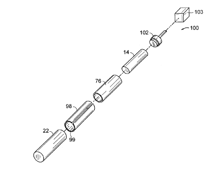
Figure 2 is an exploded perspective. view illustrating
3o a manner in which the detector IO may be assembled. After
appropriately wrapping the crystal 14 with the reflecting
layer 74, the crystal 14 is inserted into the boot 76 and
'the boot 76 in the sleeve 98 to form the crystal-boot-
16
CA 02212273 1997-08-O1
BI-3226
sleeve subassembly. At this point, the outside diameter of
the sleeve 98, with the boot in an uncompressed state, will
be greater than the inside diameter of the metal casing 22.
Therefore, to insert the sleeve 98 into the casing 22, a
radial compression force is applied to the sleeve 98 at an
end first to be inserted into the casing to compress the
sleeve 98 sufficiently to enable insertion of the
subassembly into the casing 22 preferably with the use of a
forcing mechanism 100. The forcing mechanism 100, for
l0 example, may consist of a hydraulic ram or push rod 102
coupled to a conventional control apparatus 103 for pushing
the crystal-boot-sleeve subassembly into the casing 22.
After a first incremental insertion of the subassembly into
the casing, the radial compression force.is then re-applied
to the sleeve 98 at a location spaced a short distance from
the sleeve/casing interface to facilitate further insertion
of the sleeve 98 into the casing 22. The steps are then
repeated until the sleeve 98 entirely resides within the
casing 22.
The incremental compression preferably is accomplished
with a radial clamp 104, for example a compression ring,
secured to the sleeve 98 as illustrated in Figure 3. Each
time the radial clamp 104 is secured to the sleeve 98, a
length of the sleeve 98 will be sufficiently compressed for
insertion into the casing 22. The length of the sleeve 98
available for. insertion is a function of the axial rigidity
of the sleeve 98. For example, a sleeve.98 having very
little axial rigidity would have a small length available
3o for insertion while a sleeve 98 having substantial axial
rigidity will have a longer length available for insertion.
The axial rigidity of the sleeve 98 will therefore
necessarily impact the location at which the radial clamp
17
CA 02212273 1997-08-O1
BI-3226
104 is applied to the sleeve 98. An axial rigidity is
selected such that a length of 0.25 inch may be inserted
into the casing 2.2 at one time. An axial rigidity may be
selected to allow, for example, 0.5 inch insertion to be
effectuated or alternatively allow 1.0 inch or greater
insertion before the need to reposition the radial clamp,
or other compressing device. Accordingly, the crystal-
boot-sleeve subassembly may be progressively inserted at
increments ranging from about 0.25 inch to 1.0 inch, or
l0 more .
The insertion process of Figure 2 benefits from the
metal-to-metal interface between the sleeve 98 and casing
22 which substantially reduces the coefficient of friction
relative to metal-to-boot interface which would exist
without the sleeve 98. The boot 76 typically will have a
higher coefficient of friction with the casing 22 than the
sleeve 98. Therefore, for a desired radial loading
(obtained by compressing the sleeve-boot-sleeve subassembly
by a desired percentage of its uncompressed dimension), it
will be substantially more difficult to insert the crystal
14 and boot 76 into the metal casing 22 without the sleeve
98. Further, for large radial loadings, such as those
necessary to obtain the above described shifting of the
resonant frequencies of the detector assembly for MWD
applications, it is extremely difficult if not impossible
to insert, while maintaining the integrity thereof, a
crystal-boot subassembly into the casing 22 without the
sleeve 98 due to the substantial coefficient of friction
3o between the boot 76 and casing 22. At such radial loading
levels, insertion. of a crystal-boot subassembly (sans
sleeve) directly into the casing 22 undesirably would cause
damage to the boot 76, thereby substantially reducing the
18
BI-3226
CA 02212273 1997-08-O1
boot's functionality as a shock absorber for the high
vibration environment experienced by the detector 10. The
use of the sleeve 98 enables a substantially higher radial
compression force to be achieved while maintaining the
integrity of the boot.
Although the invention has been shown and described
with respect to certain preferred embodiments, it is
evident that equivalent alternation and modifications will
l0 occur to others skilled in the art upon the reading and
understanding of this specification and the annexed
drawings. In particular regard to the various functions
performed by the above described elements (components,
assemblies, devices, compositions, etc.), the terms,
including a reference to a "means" used to describe such
elements are intended to correspond, unless otherwise
indicated, to any element which performs the specified
function of the described element (i.e., that is
functionally equivalent), even through not structurally
equivalent to the disclosed structure.
19