Note: Descriptions are shown in the official language in which they were submitted.
CA 0221242~ 1997-08-06
FASTENERS
Philip A. Kuhns
BACKGROUND AND SUMMARY OF THE INVENTION
The present invention is directed to fasteners,
and more particularly, to fasteners having a generally U-
shaped, staple-like construction, to driving elements and
fastener placement systems therefor, to sticks of the
fasteners, to methods of fastening and to fastened
workpieces.
A wide variety of forcibly driven fasteners have
been employed in the past for the fastening together of
two or more workpieces. Such fasteners have included
everything from ordinary construction nails to U-shaped,
staple-like fasteners. In some instances in the past a
plurality of the fasteners are formed into a stick which
can be inserted into a tool for positioning and driving
the fasteners into the workpieces which are to be fastened
together. During the fastening procedure, the sharp
leading ends of the spaced legs of the staple-like
fasteners are positioned over at least one of the
workpieces to be fastened, and a driving element in the
tool is forcibly driven against the crown which joins the
legs of one of the staple-like fasteners to separate the
leading fastener from a stick of the fasteners, and
forcibly drive it into the workpiece or workpieces.
Nails have also been employed in the past in
which the nails are adhesively and sequentially attached
to each other to form a stick of the nails, the stick is
inserted into the magazine of a fastener driving tool in a
manner similar to the aforementioned staples, and a
driving element of the driving tooi contacts and forcibly
CA 0221242~ 1997-08-06
--2--
drives the lead nail in the stick into the workpieces
being fastened together.
Although in many of the prior fasteners and
fastener systems a force is applied when the fastener is
in the process of being forcibly driven into the
workpieces which are being fastened, once driving of the
fastener has been completed, any forces of substantial
magnitude which may have existed during the driving step
and which might have tended to urge two workpieces
together generally cease. Moreover, neither the
configuration of the prior fasteners nor the manner in
which they are driven to achieve the fastening function
have been generally conducive to exerting any substantial
continuing force which tends to urge the two workpieces
together once the fasteners are in place. It would be
desirable if a continuing force could be exerted after the
driving of a fastener has ceased and which force would
tend to urge the two workpieces together in their fastened
condition. The existence of such continuing force would
among other things firmly hold the workpieces together
after fastening and during handling and use of the
fastened workpieces. This would substantially reduce any
tendency or possibility of relative movement between the
two workpieces after they have been fastened together and
the possible misalignment or separation of the workpieces
due to such movement.
It has been discovered in the present invention
that continuing forces advantageously may be simply,
easily and readily achieved which tend to urge and hold at
least two workpieces together both during the forcible
driving of the fastener or fasteners, as well as after the
fastener has been forcibly driven and placed in the
workpieces. In the present invention these desired
continuing forces are achieved by utilizing a U-shaped,
staple-like fastener having a pair of legs which are
spaced from each other by a crown which transversely
extends between the upper ends of the legs to connect the
CA 0221242~ 1997-08-06
legs to each other adjacent their upper ends, but space
the upper ends apart by a given distance. During or at
the completion of the driving of the fastener into the
workpieces, action is taken on or by the fastener which
tends to or attempts to shorten the distance between the
upper ends of the legs. This results in the generation
and exertion of forces which act to continue to urge the
two workpieces together after the placement of the
fastener as will be described in further detail to follow.
Another advantage of the present invention is that these
continuing forces may be easily and readily accomplished
utilizing generally previously known and available
fasteners, and the desired continuing forces may be
accomplished without the need to employ complex or
expensive specially constructed tools or procedures.
In one principal aspect of the present
invention, an improved driving element, fastener placement
system, method of fastening and combination of fastened
workpieces comprises a generally U-shaped, staple-like
fastener having a pair of legs spaced from each other by a
crown which transversely extends between the upper ends of
the legs to connect the legs to each other adjacent their
upper ends and space the upper ends of the legs apart by a
given distance. Each of the legs also has an opposite
lower end which is adapted to enter the respective
workpieces which are to be fastened together. The
fastener is positioned with the lower end of one leg in
contact with one of the workpieces and the lower end of
the other leg in contact with the other workpiece, and the
fastener is then forcibly driven into the respective
workpieces by a driving element which acts upon the crown
in a manner to attempt or tend to shorten the distance
between the upper end of at least one of the legs and the
other leg. This will create continuing forces which tend
to continue to urge the respective workpieces together
after the fastener has been driven~
CA 0221242~ 1997-08-06
--4--
In another principal aspect of the present
invention, the attempt to shorten the distance is produced
by bending the fastener crown.
In still another principal aspect of the present
invention, the crown is bent adjacent the upper end of at
least one of the legs to urge the upper end of that leg
toward the other leg.
In still another principal aspect of the present
invention, the crown is bent intermediate the upper ends
of both of the legs to urge the upper ends of the legs
toward each other.
In still another principal aspect of the present
invention, the bending of the crown is achieved by at
least one projection extending from an edge of the driving
element of a powered driving head toward and into contact
with the fastener crown, and the projection forcibly
drives the crown into the workpieces while at the same
time tending to bend the crown.
In still another principal aspect of the present
invention, the bent portions of the crown are countersunk
into the workpieces.
In still another principal aspect of the present
invention, prior to being driven into the workpieces the
legs of the fastener are closer to each other adjacent the
ends at which they are attached to the crown than at the
opposite ends to produce, at least in part, the continuing
forces which tend to continue to urge the respective
workpieces together after the fastener has been driven.
In still another principal aspect of the present
invention, a stick is formed of a plurality of generally
U-shaped fasteners which are arranged in serial adjacent
relationship to each other and along a longitudinal axis.
Each of the fasteners comprises a pair of elongate legs
spaced from each other and depending at one end from,
attached to and extending at a substantial angle from the
opposite ends of a crown which extends transversely
between the ends of the legs of each of the fasteners.
CA 0221242~ 1997-08-06
--5--
Both of the legs and the crown of each fastener are
located in a plane, the planes of adjacent fasteners are
substantially parallel to each other, and the longitudinal
axis extends at an acute angle to the planes of the
fasteners.
In still another principal aspect of the present
invention, the two workpieces fastened together are wood
construction pieces.
In still another principal aspect of the present
invention, the two workpieces may each include planar
faces in which the planes of the respective faces are
either parallel to each other, coplanar to each other, or
extend at a substantial angle to each other, and the legs
of the fastener may be inserted through each of the
respective planes with the crown of the fastener extending
between the respective planes to fasten the two workpieces
together.
These and other objects, features and advantages
of the present invention will be more clearly understood
through a consideration of the following detailed
description.
BRIEF DESCRIPTION OF THE DRAWINGS
In the course of this description reference will
frequently be made to the attached drawings in which:
FIG. 1 is an overall, partially exploded and
broken perspective view of a powered driving tool
positioned to fasten together a pair of workpieces in
accordance with the principles of the present invention,
in which the fastener is to span generally coplanar faces
of the workpieces which are to be fastened together, and
in which a stick of fasteners in accordance with the
invention is shown for illustration as exploded from the
tool;
FIG. 2 is a partially broken enlarged view of
the stick of fasteners substantially as shown exploded in
CA 0221242~ 1997-08-06
--6--
FIG. 1, and ready for insertion into the powered driving
tool of FIG. 1;
FIG. 3 is a broken, cross-sectioned side
elevation view of the workpieces and a fastener and
showing a first embodiment of fastener and driving element
in accordance with the principles of the present
invention, and as substantially viewed along line 3-3 of
FIG. 1;
FIG. 4 is a broken, cross-sectioned side
elevation view similar to FIG. 3 and showing the
embodiment of fastener and driving element shown in FIG.
3, but with the fasteners installed from a different
aspect and spanning the planar faces of the workpieces
which instead of being substantially coplanar to each
other as in FIGS. 1 and 3, are at a substantial angle to
each other;
FIG. 5 is a broken, cross-sectioned side
elevation view of the workpieces having coplanar faces and
having a driving element both of which are similar to FIG.
3, but showing a second embodiment of fastener in
accordance with the principles of the present invention;
FIG. 6 is a broken, cross-sectioned side
elevation view similar to FIG. 5 and showing the
embodiment of fastener and driving element shown in FIG.
5, but with the fasteners installed from a different
aspect and spanning the planar faces of the workpieces
which instead of being substantially coplanar to each
other as in FIG. 5, are at a substantial angle to each
other;
FIG. 7 is a broken, cross-sectioned side
elevation view of the workpieces having coplanar faces and
having a fastener both of which are similar to FIG. 3, but
showing a second embodiment of driving element in
accordance with the principles of the present invention;
FIG. 8 is a broken, cross-sectioned side
elevation view similar to FIG. 7 and showing the
embodiment of fastener and driving element shown in FIG.
CA 0221242~ 1997-08-06
7, but with the fasteners installed from a different
aspect and spanning the planar faces of the workpieces
which instead of being substantially coplanar to each
other as in FIG. 7, are at a substantial angle to each
other;
FIG. 9 is a broken, cross-sectioned side
elevation view of the workpieces having coplanar faces and
having a fastener both of which are similar to FIG. 3, but
showing a third embodiment of driving element in
accordance with the principles of the present invention;
and
FIG. 10 is a broken, cross-sectioned side
elevation view similar to FIG. 9 and showing the
embodiment of fastener and driving element shown in FIG.
9, but with the fasteners installed from a different
aspect and spanning the planar faces of the workpieces
which instead of being substantially coplanar to each
other as in FIG. 9, are at a substantial angle to each
other.
DESCRIPTION OF THE PREFERRED EMBODIMENTS
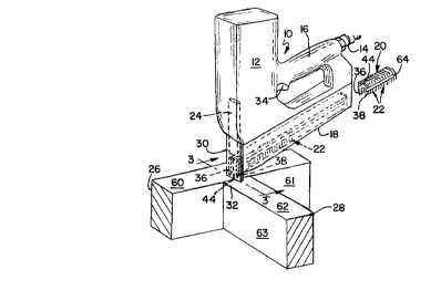
A powered driving tool, generally 10, is shown
in FIG. 1 and which comprises a motor housing 12 for
containing some form of motor, piston or other driving
component (not shown) for forcibly driving the fasteners
of and in accordance with the present invention as will be
described in further detail below. The motor in the motor
housing 12 may be driven by any one of a number of
conventional power sources, including for example
pressurized fluid, electrical or combustion power sources.
For purposes of illustration only, a pneumatic fitting 14
is shown in FIG. 1 for communicating a source (not shown)
of high pressure air of for example 110 psi through a
handle 16 of the powered driving head. The handle 16 is
preferably provided for manually positioning and holding
the powered driving tool 10 relati~e to the workpieces
which are to be fastened toyether so that the fastening
CA 0221242~ 1997-08-06
function as will be described further below, may be easily
and efficiently performed.
The powered driving tool 10 also preferably
includes a magazine 18 for receiving and positioning a
stick 20 of a plurality of fasteners 22 for use in
accordance with the invention, and as seen in FIGS. 1 and
2. The fasteners 22 of the present invention are
preferably generally U-shaped and staple-like in nature as
best seen in the drawings. The powered driving tool 10
also includes a driving element 24 which is positioned to
be driven by the motor in motor housing 12 in a manner so
as to reciprocate to drive the fasteners 22 sequentially
and one at a time from the stick 20 into the workpieces 26
and 28 which are to be fastened together as shown in the
drawings.
As best seen in FIG. 1, the powered driving tool
10 may include a cover plate 30 behind which the lead
fastener 22 in the stick 20 is positioned in readiness for
being forcibly separated from the stick and driven into
the workpieces 26 and 28 to be fastened together. The
cover plate 30 is preferably approximately the same width
as the fastener 22 and may provide any one of several
functions. One function is to position the lead fastener
22 in the stick 20 in position for driving. Another is to
provide a safety shield to prevent possible injury to the
operator of the powered driving head 10, and define the
leading end of the magazine 18. Still another is to
permit accurate positioning of the powered driving tool 10
relative to the workpieces prior to driving the fastener
by contacting and resting the lower edge 32 of the cover
plate 30 on the workpieces 26 and 28 as shown in FIG. 1.
Once the powered driving tool 10 has been positioned in
its desired location, it may be actuated by a suitable
trigger 34 or the like to forcibly separate the lead
fastener which is positioned just behind the cover plate
30 and drive it into the workpieces 26 and 28.
CA 0221242~ 1997-08-06
_g _
The magazine 18 is preferably angled relative to
the motor housing 12, as shown in FIG. 1, to facilitate
the manual manipulation ~nd positioning of the powered
driving tool 10 relative to the workpieces 26 and 28 to be
fastened together. This angular configuration relative to
the motor housing 12 and driving element 24 is
particularly advantageous where the powered driving tool
10 is to be positioned so as to drive the fasteners
between the faces of respective workpieces which are
positioned at a substantial angle to each other for
example as shown in FIG. 4. Although angular positioning
of the magazine 18 is preferred, it will be understood
that the magazine 18 and motor housing 12 may be
positioned at right angles, without departing from the
spirit and scope of the present invention. It will also
be understood that some fo.m of conventional spring or the
like (not shown) may be provided in the magazine 18 to
urge the stick 20 of fasteners forward so that they are
properly, automatically and sequentially positioned for
driving by the driving element 24.
With particular reference to FIGS. 1-4, a first
preferred embodiment of generally U-shaped, staple-like
fastener 22 of the present invention comprises a pair of
elongate spaced legs 36 and 38 which are spaced from and
extend generally parallel to each other as best seen in
FIG. 3. The upper ends 40 and 42 of the respective legs
36 and 38 of the U-shaped, staple-like fastener 22 are
connected by a crown 44 which is connected at its ends 46
and 48 to the upper ends 40 and 42, respectively, of the
legs 36 and 38 of the fastener. The bottom ends 50 and 52
of the fastener 22 opposite the upper ends 40 and 42,
respectively, are preferably cut cr otherwise formed to a
sharp point, as best seen in FIGS. 3 and 4, to facilitate
their forcible entry into the workpieces 26 and 28.
A first embodiment of driving element 24 of the
invention i~ shown in FIGS. 1-4 fo~ driving the fasteners
22. The driving element 4 has a lower edge 54, as best
CA 0221242~ 1997-08-06
--10--
seen in FIGS. 3 and 4, which is adapted to align with the
crown 44 of the leading fastener 22 which is to be next
driven by th~ powered drivina haa~ 10 as seen in FIG. 1.
This lower edge 5~, according to che first embodinlent of
driving elemerlt 24 of the present invention, includes a
pair of spaced projections 56 and 58 which extend
downwardly from and at each of the ends of the lower edge.
The projections 56 and 58 are each shorter than the length
of the crown 44 in the direction parallel to the crown 44.
The projections 56 are positioned to contact the crown
ends 46 and 48, respectively, of the fastener 22, as best
seen in FIGS. 3 and 4, and overlie the elongate leg~ 36
and 38 of the fastener. Because of this posi~ioning, the
legs 36 and 38 are directly driven into the workpieces 26
and 28, as best seen in FIGS. 3 and 4 by forces shown by
the solid arrows f.
Accordingly, the forces f generated by the
powered driving tool 10 and transmitted through the
projections 56 and 58 are concentrated of forces directly
over the legs 36 and 38. This concentration of forces
produces several advantageous results of the present
invention. One is to rapidly and directly drive the legs
36 and 38 into the workpieces 26 and 28. Secondly, by
concentrating the forces exerted by the powered driving
tool 10 in the projections 56 and 58, rather than along
the whole linear length of th~ edge 54 of the driving
element 24, recoil in the powered driving tool 10 is
substantially reduced.
A third and im~ortant result of the spaced
projections 56 and 58 is that once the legs 36 and 38 of
the fastener have been driven into the respective
workpieces 26 and 28, the concentrated forces shown by the
solid arrows f in FIG. 3 which are directed through the
projections 56 and 58 will tend to bend the crown 44 of
the fastener in the manner to assume the crown shape 44A
shown in FIG. 3. Although substantial bending of the
crown in this manner is greatly restricted and virtually
CA 0221242~ 1997-08-06
--11--
precluded because the elongated legs 36 and 38 already
have been driven over their length into the material of
the workpieces, some bending will occur due to the
resilience of the workpiece material, which typically is
wood. Thus, the distance between the upper ends 40 and 42
of the fastener legs 36 and 38, along with the
corresponding ends 46 and 48 of the crown 44 will tend or
attempt to shorten and they will be countersunk into the
respective workpieces 26 and 28, as seen in FIGS. 3 and 4.
This bending action on the crown 44 of the fastener 22
and/or countersinking which tends to shorten the distance
between the respective upper ends 40 and 42 of the legs 36
and 38 is minimized due to the resistance resulting from
the density of the workpiece materials as stated,
substantial forces F instead will be set up in the
workpieces 26 and 28 as shown by the hollow arrows in
FIGS. 3 and 4. As will be seen in FIGS. 3 and 4, these
forces F are exerted either directly in a direction or
which will have a substantial component in a direction
which tends to urge the two workpieces 26 and 28 which are
spanned by the fastener 22 further together with a
continuing force after the fastener 22 has been forcibly
driven into the workpieces.
With particular reference to FIG. 1, the
workpieces 26 and/or 28 may be formed of any number of
widely varying materials which are capable of receiving
the forcibly driven fasteners 22 and which will retain the
fasteners after they have been forcibly driven in a manner
to hold the workpieces together. With particular
reference to FIG. 1, the workpieces may typically be
formed of a generally fibrous and/or cellular material,
such as wood and, more specifically, may be wood
construction materials such as where workpiece 26 is a
sill plate or piece and workpiece 28 is a stud and where
the workpieces are to be assembled and fastened together
in the construction of a wall of a building structure.
CA 022l242~ l997-08-06
-12-
Also with particular reference to FIGS. 1, 3 and
4, the workpieces 26 and 28 may be generally rectangular
in cross-section, with workpiece 26 having at least two
generally planar faces 60 and 61, and workpiece 28 also
having at least two generally planar faces 62 and 63.
Referring to FIGS. 1 and 3, the planar faces 60 and 62 of
the workpieces 26 and 2 8 may be arranged so that they are
parallel and/or coplanar to each other, and the fastener
22 may be positioned to extend across and fastened through
these two parallel and/or coplanar faces 60 and 62. In
another preferred alternative, the fastener 22 extends
between and fastens the planar faces 61 and 63 of the
respective workpieces 2 6 and 28 which are arranged at a
substantial angle to each other as seen in FIG. 4. For
example, this would be typical in the fastening of sill
plate and stud workpieces respectively in a building
construction to form a wall. In the fastening of such
building construction elements as seen in FIG. 4, one or
more fasteners 22 are preferably forcibly counterdriven on
each side of the workpiece 28 to maximize the fastening
strength.
It has been found that the utilization of the U-
shaped, staple-like fasteners of the present invention
together with the manner of forcibly driving the fasteners
as just described in which a continuing force will be
exerted between the workpieces which have been fastened
due to the attempt or tendency to shorten the fastener
crowns 44 by bending, will result in a substantially
stronger and stationary fastening between the workpieces
than where either nails or staples as in the past are
simply used. Moreover, the strength and rigidity of
joinder is also substantially improved where the U-shaped
fasteners 22 are driven, as shown in FIG. 4, so that their
crowns 44 extend between the angular planar faces 61 and
63. These stronger fastenings will permit extensive
transport and handling of preassembled prefabricated
structures, such as building walls, without slippage,
CA 022l242~ l997-08-06
--13--
movement, separation or misalignment of the workpieces
relative to each other.
With further particular reference to FIGS. 1 and
2, the fasteners 22 of the present invention, as
previously mentioned, are preferably arranged into a stick
form for ease of handling and use, and in which plural
fasteners 22 are sequentially fixed to each other as best
seen in FIG. 2 to form the stick 20. This facilitates the
positioning of the fastener sticks 20 in the magazine 18
of the powered driving head lo, and also sequentially
positions the respective fasteners 22 so that they may be
forcibly driven one by one in the proper orientation into
the workpieces 26 and 28 by the driving element 24.
The stick 20 of fasteners 22 is preferably
assembled along a longitudinal axis a-a, as seen in FIG.
2, and the plane p-p of each of the fasteners 22
preferably extends at an angle to the axis a-a as shown.
This permits the stick 20 to be inserted into and
positioned in the angularly disposed magazine 18 as shown
in FIG. 1, and yet the fasteners 22 will be substantially
vertically disposed in a vertical plane p-p in readiness
for the sequential driving of the fasteners 22 vertically
into the workpieces 26 and 28. Although the respective
adjacent fasteners 22 may be formed in an integrally
stamped attached manner in which sticks of staples are
otherwise typically formed, it is preferred that the
individual fasteners 22 be independently formed, then
oriented with their planes p-p parallel to each other and
at an angle to axis a-a, and then attached together by an
elongate strip of adhesive tape 64, as shown in FIG. 2.
Alternatively, the adjacent fasteners 22 may be attached
together simply by any one of a number of known adhesives
66 which may be topically applied, as shown in FIGS. 3 and
4, to the legs 36 and 38 of each of the fasteners. This
adhesive 66 may also be utilized to firmly anchor the
fasteners in the workpieces once they have been forcibly
driven. If desired when used for the last mentioned
CA 0221242~ 1997-08-06
function, the adhesive 66 may be responsive to the heat
that is generated during the driving of the fasteners to
reduce its stickiness during driving and restore it upon
cooling.
FIGS. 5 and 6 are substantially identical to
FIGS. 3 and 4, except that a somewhat modified second
embodiment of fastener 22' is shown in FIGS. 5 and 6. As
in the case of FIG. 3, FIG. 5 depicts the workpieces 26
and 28 having coplanar faces 60 and 62 with the crown 44
of the fastener 22' spanning these coplanar faces. As in
the case of FIG. 4, FIG. 6 depicts planar faces 61 and 63
of the workpieces 26 and 28, respectively, in which the
planar faces extend at a substantial angle to each other,
and in which the crowns 44 of the fasteners 22' span these
planar faces which are at a substantial angle to each
other. Because many of the components shown in FIGS. 5
and 6 are substantially identical to those already
explained in reference to FIGS. 3 and 4, like reference
numerals will be used to identify like components for
purposes of simplicity.
In the second embodiment of fastener 22' shown
in FIGS. 5 and 6, the principal difference is that the
legs 36' and 38' of the fastener are preferably angled
outwardly somewhat rather than extending parallel to each
other as do the legs shown in FIGS. 3 and 4. The legs 36'
and 38' are angled outwardly somewhat from each other so
that their bottom ends 50 and 52 are further apart than
their top ends 40 and 42 prior to being driven into the
workpieces. Therefore, as the legs 36' and 38' are being
forcibly driven into the workpieces by the powered driving
tool 10 and driving element 24, the distance between the
legs will tend to progressively decrease as the fastener
22' enters the workpieces. However, due to the density of
the material of the workpieces 26 and 28, the legs 36' and
38' will be substantially restrained from moving toward or
closer to each other. However, this will set up
substantial forces as previously described and which tend
CA 022l242~ l997-08-06
--15--
or attempt to force the two workpieces 26 and 28 together
and which contribute to the forces F as shown by the
hollow arrows in FIGS. 5 and 6. It will also be
appreciated that these forces will continue to be exerted
after driving of the fasteners 22' has-been completed.
The driving element 24, as shown in FIGS. 5 and
6, is substantially identical to the driving element shown
in FIGS. 3 and 4. Accordingly, the forces f as shown in
FIGS. 5 and 6 will also tend to bend the crown 44 to
assume the configuration 44A as shown in FIGS. 5 and 6,
and to countersink the ends of the legs 40 and 42 and ends
46 and 48 of the crown 44A into the workpieces 26 and 28
as previously described. This will also contribute to the
forces F as shown in FIGS. 5 and 6 and which also tend to
force the workpieces together as previously described.
FIGS. 7 and 8 are also substantially identical
to FIGS. 3 and 4, except that a somewhat modified second
embodiment of driving element 24' is shown in FIGS. 7 and
8. As is the case of FIG. 3, FIG. 7 depicts the
workpieces 26 and 28 having coplanar faces 60 and 62 with
the crown 44 of the fastener 22 spanning these coplanar
faces. As in the case of FIG. 4, FIG. 8 depicts planar
faces 61 and 63 of the workpieces 26 and 28, respectively,
in which the planar faces extend at a substantial angle to
each other, and in which the crowns 44 of the fasteners 22
span these planar faces which are at a substantial angle
to each other. Because many of the components shown in
FIGS. 7 and 8 are substantially identical to those already
explained in reference to FIGS. 3 and 4, like reference
numerals will be used to identify like components for
purposes of simplicity.
In the second embodiment of driving element 24'
shown in FIGS. 7 and 8, the principal difference is that
an additional projection 68 has been added intermediate
the projections 56 and 58. Projection 68 also is
positioned to extend downward and into contact with the
crown 44 of the fastener 22, but intermediate the ends 46
CA 0221242~ 1997-08-06
- 16 -
and 48 of the crown. The projection 68 extends downward
from the edge 54 of the driving element 24 l preferably for
about the same distance as the other projections 56 and
58, and more preferably for a slightly greater distance
than the projections 56 and 58 as shown in FIGS. 7 and 8.
Accordingly, the forces f as shown in FIGS. 7 and 8 will
tend to bend the crown 44 to assume the configuration 44B
as shown in FIGS. 7 and 8. This bending will first begin
intermediate the ends 46 and 48 of the crown and then at
the ends of the crown. This will result in countersinking
of the middle 70 of the crown and also the ends 40 and 42
of the legs 3 6 and 38 and ends 4 6 and 48 of the crown into
the workpieces 26 and 28. Again, this bending and
countersinking will produce the forces F, as shown by the
hollow arrows in FIGS. 7 and 8, and which tend to force
the workpieces together, as previously described, and
after the driving of the fasteners has been completed.
FIGS. 9 and 10 are substantially identical to
FIGS. 7 and 8, except that a somewhat modified third
embodiment of driving element 24ll is shown in FIGS. 9 and
lo. As in the case of FIG. 7, FIG. 9 depicts the
workpieces 26 and 28 having coplanar faces 60 and 62 with
the crown 44 of the fastener 22 spanning these coplanar
faces. As in the case of FIG. 8, FIG. 10 depicts planar
faces 61 and 63 of the workpieces 26 and 28, respectively,
in which the planar faces extend at a substantial angle to
each other, and in which the crowns 44 of the fasteners 22
span these planar faces which are at a substantial angle
to each other. Because many of the components shown in
FIGS. 9 and 10 are substantially identical to those
already explained in reference to FIGS. 7 and 8, like
reference numerals will be used to identify like
components for purposes of simplicity.
In the third embodiment of driving element 24ll
shown in FIGS. 9 and lo, the principal difference is that
the projection 68 has been added intermediate the length
of edge 54 of the driving element 24l~, but the projections
CA 02212425 1997-08-06
--17--
56 and 58 have been eliminated. As in the second
embodiment of driving element 24', projection 68 in this
embodiment of driving element 24" is positioned to extend
downward and into contact with the crown 44 of the
fastener 22 intermediate the ends 46 and 48 of the crown.
Accordingly, the force f as shown in FIGS. 9 and 10 will
tend to bend the crown 44 to assume the configuration 44C
as shown in FIGS. 9 and 10 intermediate the ends 46 and 48
of the crown. This will result in countersinking of the
middle 70 of the crown as in the last described second
embodiment. However, due to the absence of the end
projections 56 and 58, the ends 40 and 42 of the legs 36
and 38, and ends 46 and 48 of the crown will not be
substantially bent or countersunk as in the second
embodiment of driving element. The bending and
countersinking of the middle 70 of the crown 44 again will
produce the forces F, as shown in FIGS.'9 and 10 by the
hollow arrows, and which tend to force the workpieces 26
and 28 together as previously described.
Although fasteners in which the legs 36 and 38
and/or crown 44 are from about 1-2 inches in length have
been found to be quite functional for attaching and
holding construction workpieces of wood for the assembly
of building walls, smaller or larger fasteners may be
employed either for the same or other uses.
From the foregoing, it will be appreciated that
in the present invention a continuing force is made
possible which can be exerted after the driving of a
fastener has ceased, and which force will tend to urge the
two workpieces together in their fastened condition. The
existence of this continuing force will function to firmly
hold the workpieces together after fastening and during
handling and use of the fastened workpieces. This will
substantially reduce any tendency or possibility of
relative movement between the two workpieces after they
have been fastened together, and any misalignment or
separation of the workpieces due to such movement. It
CA 0221242~ 1997-08-06
--18--
will also be appreciated that these continuing forces may
be easily and readily accomplished utilizing generally
previously known and available fasteners, and the forces
may be accomplished without the need to employ complex or
5 expensive specially constructed tools or procedures, and
while minimizing recoil during forcible driving placement
of the fasteners.
It will be understand that although certain
embodiments of fasteners 22 and 22' have been shown and
10 described as used in conjunction with certain driving
elements 24, 24' and 24", it is not necessary that a
particular embodiment of fastener be used with the
particular embodiment of driving element with which it is
shown herein. Any of the driving elements may be used
15 with any of the fasteners. For example, even though
driving element 24 is shown in FIGS. 5 and 6 as used in
conjunction with fastener 22', either driving element 24
and 24" could also be used with fastener 22'.
It will also be understood that the preferred
20 embodiments of the present invention which have been
described are merely illustrative of the principles of the
present invention. Modifications may be made by those
skilled in the art without departing from the true spirit
and scope of the invention.