Note: Descriptions are shown in the official language in which they were submitted.
6.RUG.1997 13:09 NED. ocTRoOI~URERU 31 70 ~ NO.734 P 5 CA 022l244l l997-08-07
FleYible abrasive member
~he inve~tion relates to ~ flexible abra6ivQ ~e~bQr, coupri6in6 a
porous sheet carrying deposit~ which conslst of n metal cont~ nE
abr~sive particles, which deposlt3 have been applied to the porous
sheet by ele~tr~plaling ~nd which sheet has been i~rc6-~ated with a
coating for stPh;lizing the deposits.
Such an abrasive member is ~enerally known. In the proce6s o~
ranuf~cturing such members, first of Qll me~al deposit~ ~re formed by
e,g. electrodeposition, currentle~s ~ediment~tion or vacuum
depo~ition. These deposit~ cont~in the abr~sive particles, which
provlde ~he member ~lth i~s ~brasive character.
In a second ~tep, a coatin~ i6 applied onto the porou6 sheet~ and
in the areas thereof ~etween the deposits. Thereby, a st~bilis~tion of
the deposits should be obtainsd.
In practice, the degree of st~bilisation thus oblained i6 not
fully ~tisfsctory, because the backslde of the deposits consist of
~etal deposlts (the most used is nickel) ~hich are flat and ha~e a
Z0 surface whlch ~ppears to be "polighed".
First it ls c~L-~2~ di~ficult ~o glue ~nythlng to ~ nlckel
6urface with at the same time ~aint~in; ng the flexibility . Even if the
nlckel s~rface is primed or etched. the adhesion qua~itie~ are not
i~proved 6ub6tantially,
2~ ~he consequence i5 that all abrasive~ made by well known
techniques have very low mechanic21 resi~t~nce nnd c n ~here~or- b-
e~slly dam~ed. In patont application PCT/~L 95100265. already a
co~ rable i~,~o~. ~t of this proble~ has been achieved by creat~ng
oavitie~ on the underside of the nickel depo~it. Thi6 solu~lon has
~L~V~d the a & eqion oP the metal deposit to its back carrier sheet
considerably. It is able to withstand high lateral forces ~nd is
therefore a very re~i~tant product.
The proble~ o~ damage~ caused to levera~e forces has however not
been solved yet ~nd this i8 ~he subject of the present invention.
The object of the invention is therefore to pro~ide an abrasive
me~ber of che kind de6eribed before wherein ~ better stubili~ation of
the deposits is obteined.
.~UG.1997 13:09 NED. OCTROOI~URERU 31 70 ~ NO.734 P.6
CA 022l244l l997-08-07
Thi8 object is achieved in that the depo~itg co~prise at least
one hollow ~pace through which the 6heet extends, which hollow Qpace
1~ fllled ~ith coating m~terisl. The hollow ~pace(6) extend through
the depc6it ~nd th~ough the open. porous layer. Therefore on ~he
inside of the depo~it~ the porou~ sheet i3 part1slly ~Yr~sed ~nd can
be impre~nated wlth gl~e such ~s silicon, polye~te~, polyurethane or
epoxy glues.
The glue is thu~ mechanically interlinked to ~he depo~it Hnd th~
adheslon fro~ the deposit to ~he c~rrier back 6heet i~ 6ubstantially
ineressed a9 well as the resi6tance to le~erage forces. Thu6 a highly
resistant and strong abra~ive iB created ~ich L~ ~in.q highly flexible
with coatlng mQterlal.
~ ecause the coating in the member aceordin~ to the invention has
formed protru6ions which ex~end into the corresponAingly formed hollow
space~ in the deposits. a much greater stabilication is obtained. The
protruslon~ for~ a unity ~i~h ~he rest of the coating, which m~ke~
them lock the deposits in their position.
The hollow spaces and protrusions c~n be c~rried out in any
de~ired shapes ~nd numbers. In particular. the hollow space of a
deposit may be a through going hole. Th~reby, tbe deposies may be
stabili~ed even better. ln particular in case they are ssndwiched
between two layers of eoating, the layers bein~ interco~nected by the
through gol~g protrusion~ or columns.
Pre~er~bly. the hollo~ space is ~n e6sentially cylindricul hole.
The correspondingly shaped protrusions are c~rried out cylindrically
as well.
Of course. sever~l hollow 6paces may be applied for stAbi1islng a
deposit.
~ he invention will fur~her be described ~ith reference to 60~e
30 : 'c-i ~ts sho~n in the figures.
Figure 1 6how6 a cro~ seceion through a ~lexible abrasi~e oember
accordlng to the invention.
Figures 2 up to 4 show vlews on 6everal ~ho~i ~nts of the
invent~on.
Figure 5 shows a further ~ t.
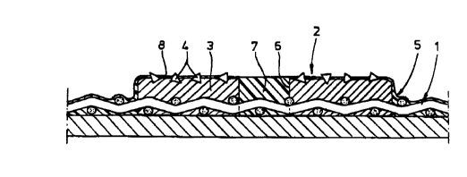
The fleYihle ~brasi~e ~ember accordlng to figure 1 contains a
porous sheet 1, carryin~ ~ d~po~it 2 which h~s been epplled by
electro-plating. The deposl~ 2 con~i6t~ of h metal oaterial 3, in
6.RUG.1~97 13:10 NED. OCTROOI~URERU 31 70 ~ 0.734 P.7
CA 02212441 1997-08-07
which abrasive particles 4 have been tm~e~ed~ The metal ~aterial 4
ha~ ~18D impregnated the porous sheet 1. Furthermore, a coatin~
material 5 has been applied which hss ~l&o been impregn-ted in the
porou6 6heet 1.
According to the invention, the deposit carries ~t lea~ one hole
6. which is also filled with the coating material. Il.L~Cr~ a t~n
18yer of coating uateri~l 8 may be present on the top 6urface of the
deposit.
The roating may compri~e a 6ilicon, polyester, polyurethane or
epoxy glue.
Due to the presence of a hole 6 in the deposit, filled with
coating material 7 which for~s a unity with the rest of the coating
material 5. a very stable po6ition of the deposit 2 with respect to
shear forces is obt~ined.
AB ~ho~n in fig~res 2 ~p to 4, the hole ln ~he deposit 2 muy t~ke
sever~l for~s~ 6uch as ~ rect~ngular hole 9 ~igure 2) or a circular
hole 9 (figure 3); also, several circular holes 11 (fi~ure 4) together
are possible.
F1sure 5 show~ ~n ~m~o~ t wherein the metal materi~l ha6 a
ca~it~ 12. whlch at the top is closed ~y metal covering material 13.