Note: Descriptions are shown in the official language in which they were submitted.
CA 02212478 1997-08-O1
FABRICATED STEER AXLE
This application relates to a fabricated axle for
wheeled vehicles. More specifically, this application
relates to a fabricated high strength non-driven axle for
wheeled vehicles.
BACKGROUND OF THE INVENTION
Typical steer axle assemblies include a forged I-
beam axle, and a pair of steering knuckles pivotally
attached to the I-beam by way of king pins. An example
of a forged non-driven steer axle is disclosed in U.S.
Patent No. 5,403,031. While such forged axles provide
for excellent strength, durability, and a high degree of
king pin mounting accuracy, they are, however, not cost
effective due to their weight and method of manufacture.
Tubular fabricated non-driven steer axles are also
known in the art. For example, in U.S. Patent No.
5,429,423 there is disclosed a tubular axle manufactured
by mating opposing axle sections constructed of sheet
material formed into channel members. The channel
members are of different lengths and connected to one
another via vertical and horizontal welds. However, the
2
CA 02212478 1997-08-O1
fabricated axle disclosed in the '423 patent includes
"in-tension" welding along the bottom of the axle in the
high stress region between the air spring mounts. This
is undesirable in view of the known axle loading
requirements present in the trucking and automobile
industries. Furthermore, the king pin mounting
structures at either end of the fabricated axle of this
patent utilize heavy and expensive forging which must be
machined. This sleeve-like forging is undesirable in
that it is both heavy and expensive to manufacture. An
additional problem associated with the axle assembly of
this patent is the large number of parts and steps
involved in its manufacture.
U.S. Patent No. 1,784,856 discloses an axle formed
of steel tubing for wheeled vehicles. As the holes at
either end of the axle are insufficient in and of
themselves to provide adequate mounting for the knuckles,
a cylindrical bearing tube or sleeve is provided at each
axle end within the holes for receiving the mounting
pins. These tubes add to the weight of the axle
assembly, and represent a drawback given current weight
limitations placed upon the trucking industry.
3
CA 02212478 1997-08-O1
Furthermore, given tolerance requirements and the number
of parts utilized, the method of manufacturing such an
axle has drawbacks of its own, including those of cost
and material.
It is apparent from the above that there exists a
need in the art for an improved non-driven non-forged
steer axle that may be manufactured in a cost effective
manner using a minimum number of parts and steps, the
axle having a reduced weight relative to current axle
designs. It is apparent that there also exists a further
need for a high strength axle which substantially
eliminates the necessity for in-tension welding in high
stress areas, and provides a means for enabling king pin
mounting accuracy in a cost effective manner.
It is a purpose of this invention to fulfill the
above-described needs in the art, as well as other needs
which will become apparent to the skilled artisan from
the following detailed description of this invention.
4
CA 02212478 1998-O1-OS
SUMMARY OF THE INVENTION
Generally speaking, this invention fulfills the
above-described needs in the art by providing an axle for
a wheeled vehicle, comprising:
an integral one piece metallic form including a
substantially U-shaped central portion and a pair of
spaced arms extending from each end of said U-shaped
central portion, the U-shaped central portion having an
open portion and a closed portion; and
a plate member located over and abridging the open
portion of the U-shaped central portion such that the
closed portion of the U-shaped central portion is in
tension during operation of the wheeled vehicle.
According to certain preferred embodiments of this
invention, the axle further includes a floating
reinforcing plate extending between each pair of spaced
arms in respective king pin mounting structures, each of
the floating reinforcing plates having an orifice defined
therein for retaining a king pin and being of sufficient
strength to provide a bearing for the king pin.
5
CA 02212478 1997-08-O1
This invention further fulfills the above-described
needs in the art by providing an axle assembly for a
wheeled vehicle, the axle assembly comprising:
first and second opposing sidewalls each extending
to a king pin mounting structure and defining a cavity
therebetween;
a king pin mounting plate having a king pin
receiving orifice defined therein, the king pin mounting
plate abridging the first and second sidewalls at one
side thereof and the receiving orifice being of a size so
as to receive the king pin in a bearing manner in order
to support the king pin against lateral movement;
a cover plate having a guide hole defined therein
through which the king pin is adapted to be fed, the
cover plate abridging the first and second sidewalls at
the other side thereof opposite the king pin mounting
plate; and
a reinforcing plate having a king pin receiving
orifice defined therein for receiving the king pin in a
bearing manner so as to support the king pin against
lateral movement, the reinforcing plate inserted and
6
CA 02212478 1997-08-O1
located in the cavity between the first and second
sidewalls adjacent the cover plate.
This invention further provides a non-driven axle
comprising: an elongated portion extending between first
and second king pin mounting means; and one of said king
pin mounting means including first, second, and third
plates having defined therein first, second, and third
orfices, respectively, for receiving a king pin.
According to certain embodiments of this invention,
a method of manufacturing the axle or axle assembly
defined above is provided.
According to still further embodiments, the axle
assembly defined above may be used in conjunction with a
lift axle suspension system for a truck or the like.
This invention will now be described with respect to
certain embodiments thereof as illustrated in the
following drawings:
BRIEF DESCRIPTION OF THE DRAWINGS
Figure 1 is a front elevational view of a steer axle
assembly according to an embodiment of this invention.
7
CA 02212478 1997-08-O1
Figure 2 is a top elevational view of the steer axle
assembly illustrated in Figure 1.
Figure 3 is a transverse cross-sectional view of the
steer axle assembly of Figure 1, taken along line 3--3.
Figure 4 is a transverse cross-sectional view of the
fabricated steer axle of Figure 1, taken along line 4--4.
Figure 5 is a transverse elevational view of the
fabricated steer axle of Figure 1, taken along line 5--5.
Figure 6 is a transverse cross-sectional view of the
steer axle assembly of Figure 1, taken along line 6--6.
Figure 7 is an exploded perspective view of one of
the king pin mounting structures of the axle of Figure 1.
Figure 8 is a top elevation view of the king pin
mounting structure of the axle shown in Figures 1 and 7.
Figure 9 is a front elevation view of one of the
elongated cover plate members of Figures 1-8 for
connecting the tops of the axle sidewalls.
Figure 10 is a top elevation view of the elongated
cover plate member of Figure 9.
Figure 11 is a top elevational view of one of the
axle end plates shown in Figures 2, 7, and 8.
8
CA 02212478 1997-08-O1
Figure 12 is a transverse elevational view of the
Figure 11 end plate.
Figure 13 is a side elevation view of one of the
floating reinforcing plates, of Figures 1, 7, and 8, that
receives the king pin in a bearing manner.
Figure 14 is a top elevation view of the Figure 13
floating reinforcing plate.
Figure 15 is a top elevation view of one of the king
pin mounting plates shown in Figures 1, 7, and 8.
Figure 16 is a side elevation view of the Figure 15
king pin mounting plate.
Figure 17 is a top elevation view of the integral
one piece metallic form of Figures 1-8, prior to its
shaping into the U-shaped member.
Figure 18 is a front elevation view of the Figure 17
integral form, after shaping into the U-shaped member
with arms extending therefrom.
Figure 19 is a transverse elevation view of the
Figure 18 form.
Figure 20 is a side plan, partially sectionalized,
view of the fabricated steer axle of Figures 1-19, as
9
CA 02212478 1997-08-O1
used in conjunction with a lift axle suspension system
for a wheeled vehicle.
Figure 21 is a front elevational view of a steer
axle assembly according to another embodiment of this
invention.
Figure 22 is a side plan, partially sectionalized,
view of the Figure 21 fabricated steer axle assembly, as
used in conjunction with a lift axle suspension system
for a wheeled vehicle.
Figure 23 is a top plan view illustrating a first
section of the combined air spring mount/suspension mount
of the Figure 21 embodiment, prior to bending and
forming.
Figure 24 is a front plan view illustrating the
Figure 23 form, after bending about the illustrated bend
lines.
Figure 25 is a side plan view of the Figure 23 - 24
air spring/suspension mount after forming.
Figure 26 is a top plan view of the other half of
the combined air spring/suspension mount for attachment
to the Figure 23 - 25 member, prior to forming.
CA 02212478 1997-08-O1
Figure 27 is a side view of the Figure 26 form,
prior to forming.
Figure 28 is a front plan view of the Figure 26 - 27
member, after bending/forming.
DETAILED DESCRIPTION OF
CERTAIN EMBODIMENTS OF THIS INVENTION
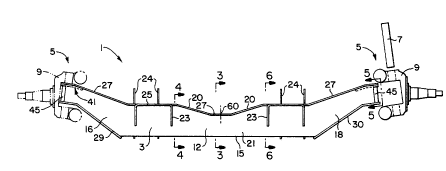
With reference first to Figure 1 there is
illustrated a steer axle assembly 1 according to this
invention. Steer axle assembly 1 includes tubular
elongated non-driven fabricated axle 3 having a king pin
mounting structure 5 at each end thereof for the purpose
of accurately mounting and supporting king pins 7 and
steering knuckles 9. Due to its design fully discussed
below, no welds are required at areas of the axle that
are in tension during normal operation of the vehicle,
and axle 3 is approximately half the weight of a
conventional forged I-beam axle.
Referring now with more particularlity to Figures 1-
6 and 17-19, axle 3 includes integral one piece metallic
form 11 (see Figs. 17-19) that itself includes vertically
oriented sidewalls 12 and 13, bottom portion 15 that
connects the sidewalls in the central substantially U-
11
CA 02212478 1997-08-O1
shaped area, and elongated arms 16-19 extending outwardly
from central U-shaped portion 21 toward king pin mounting
structures 5. Spaced apart arms 16 and 17 extend from
one end of central U-shaped portion 21 toward one king
pin mounting structure 5 while spaced arms 18 and 19
extend from the other end of U-shaped portion 21 toward
the opposite king pin mounting structure 5. As will be
discussed below, during fabrication, all welding on axle
3, in areas of high stress, is on the compression side of
the axle as opposed to the tension side. For most
vehicles using the axles of this invention, when in use,
the top side of the axle is the side in compression while
the opposite, bottom side is in tension.
Referring to Figures 1-3, air spring mounting
members 23, including support surfaces 25, and suspension
mounts 24 are attached (e. g. welded) to integrally formed
U-shaped central portion 21 in this high stress area of
the axle (i.e. the central portion of axle 3 between air
spring mounting members 23 is the most susceptible to
stress during certain vehicle operations). Bottom
portion 15 of U-shaped portion 21 extends longitudinally
(of the axle) beyond air spring mounting members 23, and
12
CA 02212478 1998-O1-OS
suspension mounts 24, in order to provide axle strength
in this high stress area between the air springs. Axle 3
has an increased vertical cross-section in the air spring
mounting areas relative to that at the center of the axle
and the king pin mounting structures 5 due to the
strength requirements associated with this section of the
axle. This is accomplished by the provision of ramp
portions which extend from either end of the central
section of the axle. There are no welds "in tension"
utilized at this section of the axle.
Top cover plate member 27 is affixed across the top
of the open end 53 of U-shaped portion 21 so that the
closed end of U-shaped portion 21 is in tension during
operation of the wheeled vehicle to which axle assembly 1
is mounted. Top plate 27 connects the upper ends of
opposing sidewalls 12 and 13 along the entire length of
axle 3, so that plate 27 extends between and connects the
opposing king pin mounting structures 5. Top plate 27
includes a pair of guide apertures or holes 28 defined
therein, one such hole 28 being located at each end of
plate 27 for the purpose of loosely receiving (i.e. in a
non-bearing manner) a corresponding cylindrical king pin
13
CA 02212478 1997-08-O1
7. Because arms 16-19 are part of sidewalls 12-13, top
plate 27 also connects the upper edges or sides thereof.
King pin mounting plates 29 and 30 also form part of
axle 3, plate 29 being mounted to the bottom of form 11
so as to connect the bottom edges of arms 16 and 17.
King pin mounting plate 30 is also mounted to the bottom
of form 11, but at the other end of the axle so as to
connect the bottom edges of arms 18 and 19. Each king
pin mounting plate 29, 30 includes a king pin receiving
orifice 31 (see Figs. 7, 15, and 16) defined therein for
the purpose of tightly receiving a corresponding king pin
7 in a bearing manner so as to rigidly support the pin 7
against lateral and tilting movement.
Figure 3 is a cross sectional view of axle assembly
1 taken along line 3--3 in Figure 1. As shown, top plate
27 closes the open end 53 of U-shaped portion 21 at the
center of the axle. Air spring supporting member 23 and
vehicle suspension mount 24 are affixed to opposite sides
of U-shaped portion 21. Figure 4 further illustrates the
U-shaped cross section of central portion 21 of axle 3,
while Figure 6 illustrates the axle's cross section along
line 6--6 in Figure 1. Apertures 33 are provided in the
14
CA 02212478 1997-08-O1
sidewalls of suspension mounts 24 so that mounts 24 can
be mounted to the vehicle suspension or the like.
According to certain embodiments of this invention,
an improved king pin-to-axle mounting assembly is
provided. As discussed above, each king pin 7 extends
through both a guide aperture 28 in top plate 27 and a
bearing orifice 31 in a corresponding king pin mounting
plate 29, 30 during vehicle operation. King pins 7
typically have a substantially constant diameter
throughout their length. Thus, because the diameter of
guide apertures 28 is substantially greater than the
diameter of bearing orifices 31, the king pins are
tightly received in orifices 31 and loosely in guide
apertures 28. Therefore, apertures 28 and 31, in plates
27 and 29, 30 respectively, can be machined in their
respective metallic plates before the axle assembly is
welded together because precise tolerances are not
required. While the accuracy of king pin mounting is
critical in all directions, the tolerance requirements
for apertures 28 and 31 are fairly loose in this design,
because king pins 7 can fit through both apertures 28 and
31 even when they are slightly offset from one another,
CA 02212478 1997-08-O1
due to the larger size of aperture 28 relative to
aperture 31. Accordingly, axle assembly 1 is easier and
more cost effective to manufacture and assemble.
Referring to Figures 5 and 7-8, a king pin
reinforcing plate 41 is adapted to be inserted into the
gap or cavity defined between sidewalls 12 and 13, at
each end of the axle, adjacent plate 27 in order to
provide a secure mounting of king pin 7. Reinforcing
plate 41 includes king pin receiving orifice 43 defined
therein for the purpose of tightly receiving king pin 7
in a bearing manner in order to provide rigid support for
same against movement. When the king pin has a
substantially constant diameter throughout its length,
the diameter of orifice 43 is substantially the same size
as the diameter of orifice 31, with both orifices 31 and
43 receiving the king pin in a supportive bearing manner.
In certain embodiments, the king pin is forcibly pressed
through orifices 31 and 43 as the diameter of the king
pin is substantially the same as that of orifices 31 and
43. After insertion, the king pin bears tightly against
the inner diametric surfaces of orifices 31 and 43 so
that the pin 7 is rigidly retained or secured during
16
CA 02212478 1997-08-O1
vehicle operation. Accordingly, plates 41 and 29, 30
provide the sole bearing surfaces for king pins 7, so
that no bearing sleeves or tubes are required. Also,
typical keyways on king pins 7 may be eliminated.
Referring still to Figures 5 and 7-8, reinforcing
plate or washer 41 is a floating member as it is not
integrally formed with either top plate 27 or the axle
sidewalls or arms. Thus, after plates 27 and 30 are
welded to sidewalls 12, 13 (and arms), reinforcing plate
41, with orifice 43 therein, is inserted into the gap
between the sidewalls until orifice 43 lines up with
orifice 31 within a predetermined tolerance. The
floating nature of plate 41 allows it to be adjusted,
after its insertion between the sidewalls, so that proper
tolerances may be achieved prior to the welding of plate
41 to the axle. Thereafter, the king pins are pressed
through apertures 43 and 31 so as to be rigidly mounted
in axle 3. As plate 41 becomes a king pin bearing
surface, plate 27 may be made of a lesser material to
20 keep costs and weight down. Another advantage associated
with this design is that orifices 28, 31, and 43 may be
machined prior to axle fabrication.
17
CA 02212478 1997-08-O1
Still referring to Figures 7-8, optionally, after
floating reinforcing plate 41 is inserted into the hollow
aperture of axle 3, the corresponding end of the axle may
be covered or closed by welding end plate 45 thereto so
as to enclose the inner cavity. End plate 45 also
functions to support plate 41 within the axle in a fixed
position. As illustrated, each end plate 45 has three
separate major planar surfaces in order to conform with
the rounded ends of axle 3 at king pin mounting
structures 5.
Figures 9 and 10 are front and top elevational views
of top plate 27, including guide holes 28 defined in
either end thereof. As can be seen, top plate 27 is
contoured to fit the tops of sidewalls 12 and 13
throughout the entire length of axle 3. Plate 27 may be
about 0.250 inches thick in certain embodiments, while
the radius of guide holes 28 may be about 1.0 inch.
Angle ~ illustrated in Figure 9, defined between central
portion 61 of plate 27 and extensions 63, may be from
20 about 10° - 30° in certain embodiments, preferably about
19.5°. Meanwhile, angle ~ may be from about 5° - 20°,
preferably about 13°.
18
CA 02212478 1997-08-O1
Figures 11 and 12 are top and transverse elevational
views, respectively, of an end plate 45. In certain
embodiments, plate 45 is approximately 0.250 inches
thick, and angle 8 may be from about 30° - 50°, preferably
about 38°.
Figures 13 and 14 are front and top elevational
views of floating reinforcing plate 41 that is adapted to
be inserted into the interior of axle 3 within the king
pin mounting structures in order to provide additional
10 support for the corresponding king pins 7. According to
certain embodiments, angle ~ may be from about 4° - 25°,
preferably about 12.96°, so that the contour of plate 41
conforms with that of top plate 27. Furthermore, plate
41 may be about Ø500 inches thick in certain embodiments
15 (substantially thicker than plate 27). The bore of
orifice 43 may be from about 1.806 - 1.808 inches in
certain embodiments, while the overall length of plate 41
may be about 4.498 inches.
Figures 15 and 16 are top and front elevational
20 views, respectively, of king pin mounting plate 29, 30
adapted to be welded to the bottom edges of the arms in
order to connect same. In certain embodiments, each
19
CA 02212478 1997-08-O1
metallic plate 29, 30 may be about 0.500 inches thick,
and angle « may be about 28.5°. Thus, plates 29, 30, and
41 are all substantially the same thickness according to
certain embodiments, with each of these being thicker
than plate 27 in order to provide the strength required
for handling the king pin bearing loads. Furthermore,
plates 29 and 30 may each be about 17.433 inches long in
certain embodiments of this invention (measured flat).
The inner diametric surfaces of orifices 31 and 43 are
king pin bearing surfaces.
Figure 17 is a top elevational view of integral one
piece metallic form 11, as it lays flat prior to bending.
From this shape, the sides of form 11 are bent
approximately 90° about lines 51 in order to form U-
shaped central portion 21 and arms 16 - 19 extending from
the ends thereof. Figure 18 is a front elevational view
of form 11 after it has been shaped by bending. In
Figure 18, after bending, form 11 includes central U-
shaped portion 21 and the spaced arms extending therefrom
at each end.
Figure l9 is a cross sectional view of the Figure 18
form 11 taken in the central portion 21 so as to
CA 02212478 1997-08-O1
illustrate bottom portion 15 of the one piece member
connecting sidewalls 12 and 13 at the closed end of the
U-shaped member.
While portion 21 is illustrated as almost perfectly
U-shaped, this need not be the case, as variations
thereof will suffice. For example, the closed end of the
U-shaped design need not be rounded, and the walls of
portion 21 need not be perfectly parallel. In other
words, clearly, variations of the illustrated U-shaped
design are envisioned herein.
Figure 20 is a side view, partially sectionalized,
of the fabricated steer axle assembly 1 of Figures 1-19
being used in conjunction with, and attached to, a wheel
bearing lift axle suspension system for a wheeled vehicle
15 (e. g. truck or trailer). The illustrated suspension
system may include at least two non-liftable wheel
bearing suspensions providing the primary means of
support for road engagement of the vehicle, and the
illustrated lift axle suspension system includes a frame
20 bracket, upper and lower control arms having first ends
pivotally attached to the frame bracket at pivot points
and second ends attached to an axle connection means.
21
CA 02212478 2000-11-O1
The lift axle suspension also includes a system for
raising and lowering the wheels of the suspension into
and out of engagement with the road surface. An
exemplary such suspension may be found in U.S. Patent No.
5,403,031.
It is pointed out that steel axle 3 may also be
utilized as a front steer axle, or as any other steer
axle on a car, trailer, or truck. In other embodiments,
the axle 3 may be flipped over from its Figure 1 position
and/or reinforcing plate 41 and a corresponding guide
hole may be located on the bottom or lower side of the
axle.
Described below is an exemplary method of
manufacturing axle assembly 1. The first step is the
forming or stamping of the integral one piece metallic
(e.g. micro-alloyed steel) form 11 shown in Figure 17.
At this initial stage, form 11 defines a single plane and
is substantially X-shaped. Thereafter, sidewalls 12 and
13 (and arms 16 - 19) of form 11 are each bent upward
approximately 90° about bend lines 51 which results in
the form 11 shown in Figures 18-19, that includes
22
CA 02212478 1998-O1-OS
substantially U-shaped central portion 21, and spaced
arms 16 - 17 extending from one end thereof and spaced
arms 18 - 19 extending from the other end thereof.
After form 11 of Figures 18-19 has been bent,
metallic (e.g. micro-alloyed steel) cover plate 27,
including guide holes 28 machined therein (see Figures 8-
9), is welded across so as to abridge open portion 53 of U-
shaped member 21 in a manner such that plate 27 extends
across the entire length of form 11 connecting sidewalls
12 and 13 from one king pin mounting area to the other.
The welding of plate 27 to the U-shaped member begins at
point 60 (see Figure 1), and the weld travel direction
for each side of plate 27 is directed toward the
respective ends of the axle. Thus, for each side of
plate 27, one weld begun at point 60 travels toward one
end of the axle while another begun at the same point 60
travels toward the other axle end.
Thereafter, metallic (e. g. micro-alloyed steel) king
pin mounting plates 29 and 30, with orifices 31 machined
therein (see Figures 15-16), are welded to form 11 so as
to connect the lower edges of the arms (16 - 19) along
the bottom of the axle opposite plate 27. The respective
23
CA 02212478 1997-08-O1
welds attaching each plate 29, 39 to U-shaped form 11
travel from the end of axle toward its center. In
certain embodiments, welds are provided along the entire
outer edges of plates 27, 29, and 30 so as to affix these
5 plates to form 11 at the edges of sidewalls 12 and 13.
Following the attachment of plates 27, 29, and 30 to
form 11, a floating metallic (e. g. micro-alloyed steel)
reinforcing plate 41, with orifice 43 machined therein
(see Figures 7-8), is inserted into the cavity defined
between sidewalls 12 and 13 at each king pin mounting
structure 5. After king pin receiving orifices 31 and 43
are aligned in a linear manner for receiving the king pin
7, plate 41 is welded to the axle so that the upper
planar surface of plate 41 abuts the lower planar surface
of plate 27. In each king pin mounting area, all three
plates 27, 29(30), and 41 are substantially parallel to
one another. As shown in Figure 8, when orifices 31 and
43 are aligned for receiving the king pin, orifice 43 is
not necessarily concentric with guide hole 28, as hole 28
has a substantially larger diameter than that of orifices
31 and 43.
24
CA 02212478 1997-08-O1
After reinforcing plate 41 has been affixed to the
axle, optionally, an end plate 45 may be welded to each
end of axle 3 so as to enclose the cavity defined by the
tubular fabricated axle.
5 Following the manufacture of axle of 3, a king pin 7
is pressed through orifices 43 and 31 at each king pin
mounting structure 5, with the end result being that each
king pin 7 extends through orifice 28 in a non-bearing
manner, and orifices 43 and 31 in a tight bearing manner.
Orifices 43 and 31 rigidly retain king pin 7 against
lateral and/or tilting movement during vehicle operation
in a non-rotatable manner. Suspension mounting members
24 and spring supports 23 may be welded to form 11 at any
point during the fabrication procedure. Upon completion
15 and in use, as shown in Figures 1-2, sidewalls 12 and 13
are substantially vertically oriented, while plates 27,
29, and 30 are oriented so as to extend substantially
horizontally.
It has been found that the above recited fabrication
20 process is easily adapted to a wide variety of
configurations with minimal tooling costs. It is also
believed that, using state of the art robotic welding,
CA 02212478 1997-08-O1
the cost of fabrication will be substantially less than
that of I-beam axle forging.
According to a typical design of axle assembly 1,
the axle 3, shown in Figure 1, may be about 75 inches in
length from end to end, have a dimension "x" of about
3.25 inches (see Figures 3-4), a dimension "yl", of about
5.0 inches (see Figure 3), a dimension "y2" of about 7.20
inches (see Figure 4), and define a distance of about
30.75 inches between the respective centers of air spring
mounts 23.
Figures 21 - 28 illustrate fabricated axle assembly
1 according to another embodiment of this invention.
Axle 3 of this embodiment is different than that of the
previous embodiment (Figures 1-20), in that a pair of
combined air spring and suspension mounting members 91
are provided on the axle. Unlike the Figure 1 - 20
embodiment, the axle assembly embodiment of Figures 21 -
28 includes members 91, each of which represents a
suspension attachment and air spring mount integrally
formed with one another. Furthermore, in the Figure 21 -
28 embodiment, top plate 27 is angled upward in areas 92
where mounts (or axle seats) 91 are attached to axle 3.
26
CA 02212478 1997-08-O1
Each of the two axle seat mounting areas 92 of axle 3
along the top of the axle 3 are angled upward relative to
the horizontal from about 5 to 50 degrees, preferably
about 20 degrees.
Figure 22 illustrates the axle assembly of Figure
21, being used in conjunction with a lift axle suspension
system attached to vehicle frame 92, the suspension
,including substantially parallel pivoting arms 93, air
spring 94, air bellows 81, pivot points 82, and hanging
bracket 95. See U.S. Patent No. 5,403,031, for more
detail regarding the illustrated lift axle suspension.
Each axle seat member 91 is made up of a first
section 96 and a second section 97 that are welded
together. Figures 23 - 25 illustrate first section 96,
while Figures 26 - 28 illustrate second section 97.
Figure 23 illustrates axle seat section or portion 96 in
its stamped or planar form, prior to bending about bend
lines 98. Portion 96 is then bent at right angles about
bend lines 98, resulting in the formed or shaped portion
96 illustrated in Figures 24 - 25. As illustrated,
shaped portion 96 includes planar ear 99 that includes
apertures 101 defined therein which allow the axle
27
CA 02212478 1997-08-O1
assembly to be attached to the suspension. From
substantially vertically aligned ear 99, cross-connecting
air spring mounting section 103 extends substantially
horizontally and is integrally formed with vertically
aligned section 104. Apertures 105 are provided in air
spring mounting section 103 so as to allow the air
springs to be mounted to the axle assembly. According tc
certain preferred embodiments, the distance between
apertures 105 may be approximately 6.20 inches, the
vertical distance between apertures 101 approximately
7.47 inches, the length of member 103 from 99 to 104 (see
Fig. 24) approximately 5.87 inches, and the horizontal
distance (see Fig. 23) from the lower aperture 101 to the
end 107 of portion 96 approximately 13.03 inches.
Figures 26 - 27 illustrate second portion 97 of axle
seat member 91, before it is welded to portion 96.
Figures 26 and 27 illustrates portion 97 in planar form
after stamping, but prior to bending or forming, while
Figure 28 illustrates portion 97 after bending/forming.
Axle seat portion 97 includes vertically aligned ear 109
(opposing ear 99) that includes suspension mounting
apertures 110 defined therein. Connected to ear 109 are
28
CA 02212478 1997-08-O1
cross-connecting member 111 to be connected to portion 96
for providing axle seat member 91 with stability, and
horizontally aligned member 112. Together, members 111
and 112 distribute the load more equally onto the axle
beam. According to an exemplary embodiment, the width
"w" of member 112 may be about 1.51 inches, while
distance "z" of member 111 may be about 2.51 inches, and
length "1" of member 111 from bend line 121 to the end of
member 111 may be about 5.87 inches. The horizontal
distance between apertures 110 may about 7.24 inches
according to certain embodiments.
As shown in Figure 21, a first portion 96 and a
second portion 97 are welded, or otherwise connected,
together so as to form each axle seat 91, each seat 91
including the air spring mount and the suspension mount
integrated into a single unit. Each member 91 is then
welded to the axle beam at areas 92 for suspension
connection. The interconnection of these parts allows
for improved load distribution onto the axle beam, as
well as ease of manufacture. With regard to the
embodiment shown in Figures 21 - 28, the angled
29
CA 02212478 1997-08-O1
transition areas 92 of plate 27 are more cost effective
to manufacture, and produce fewer stress risers.
Once given the above disclosure many other features,
modifications and improvements will become apparent to
the skilled artisan. Such other features, modifications
and improvements are therefore considered to be a part of
this invention, the scope of which is to be determined by
the following claims.