Note: Descriptions are shown in the official language in which they were submitted.
CA 02213467 1997-08-20
-1-
ESTABLISHMENT OF A FLEXIBLE RATE INTERFACE LINK TO
RESTORE CHANNELS FROM A FAILED COMMUNICATION LINK
Technical Field
This invention relates to a communication switching system having a
plurality of switching nodes, and, in particular, to the restoration of active
communication channels of a failed communication link.
Background of the Invention
In prior art switching systems comprising a plurality of identical
switching nodes, an originating switching node must set up each individual
call to a
destination switching node via an intervening switching node by involving the
intervening switching node in each call control operation such as initiation,
progress
and termination of calls. One problem with such architecture is that the
intervening
switching node is substantially performing the same amount of call processing
work
as the originating switching node and the designation switching node;
consequently,
the number of calls that can be handled by the intervening switching node is
limited.
The effect of this problem is intensified if more than one intervening
switching node
is between the originating switching node and designation switching node.
Because
of this problem, the prior art architecture of switching systems has not been
able to
utilize networks of identical switching nodes efficiently, but has been
limited to
switching nodes interconnected via special purpose hardware (either special
purpose
switching nodes, e.g., No. 4 ESS, or special center stage switching units,
e.g., No. 5
ESS or AT&T Definity Telecommunication Switching System).
U.S. Patent No. 5,182,751 resolves the above problems by disclosing a
flexible rate interface (FRI) link. The FRI link is established on a standard
ISDN
link which is terminated on an ISDN interface connected to a switching node.
On -
the standard ISDN link, the signaling channel is communicated in a D channel
of a
standard ISDN link, and the transport channels are B channels of a standard
ISDN
link. A processor controlling the switching node sets up a FRI signaling
channel on
the standard ISDN link for use by the FRI link and establishes the ISDN
standard
protocol on that FRI signaling channel. The FRI signaling channel of the FRI
link
may be established by using any of the following: a B channel of a standard
ISDN
link, standard ISDN user information transport facilities, or a logical link
of a D
channel of a standard ISDN link. Also, B channels from the standard ISDN link
are
reserved for use with the FRI link as virtual transport channels. The
processor
utilizes the FRI link and the standard ISDN link as two distinct links. The
processor
communicates signaling information on the FRI signaling channel to perform all
call
control on calls being set up or active on the transport channels assigned to
the FRI
CA 02213467 1997-08-20
-2-
link. The signaling information communicated on the FRI signaling channel is
distinct from the signaling information of the signaling channel of the ISDN
link
which controls all calls on the unassigned transport channels of the ISDN
link. Only
the endpoint switching nodes are aware of the existence of the FRI link with
respect
to call control.
In prior art telecommunications switching systems comprising a
plurality of stored program controlled switch nodes, it is well known that
when two
switch nodes are interconnected by a plurality of PRI links, to form these PRI
links
to a non-facility access service (NFAS) group. All active PRI links are part
of the
NFAS group. Within a NFAS group of PRI links, the D channels (which are
normally used for signaling) in all but two of the PRI links are utilized as
an
additional B (bearer) channel. In the two remaining PRI links, one D channel
is
designated as the primary D channel, and the D channel of the second remaining
PRI
link is designated as the secondary D channel. In accordance with CCITT
specifications, if the primary D channel is lost, then, the two switching
nodes will
utilize the secondary D channel for signaling. In accordance with the CCITT
specification, if a PRI link is lost no attempt is made to preserve the calls
on B
channels of the failed PRI link by moving them to B channels of other PRI
links
within the NFAS group or to set up new links. This results in calls being lost
even
though there is spare capacity within the NFAS group to continue these calls.
There are a number of reasons why the primary PRI link may be
disabled. One reason is that the primary PRI link is a wired link that has
been cut
accidentally. A second reason is that in a highly distributed system such as
illustrated in U. S. Patent 5,182,751 it is necessary to add and remove PRI
links
interconnecting switch nodes. At present, if calls are not to be terminated,
it is -
necessary to wait until there are no calls being communicated on any of the
links
making up the NFAS group. This is often done by indicating that each of the
links is
out of service. In general, this requires field personnel to work during the
early
morning hours when there is little activity on the system.
It is clear that a problem exists in the art with the present procedure of
simply dropping calls on B channels of a failed PRI link even if there are no
idle B
channels within the NFAS group. As noted in the previous paragraph, there are
a
variety of conditions under which such failures can happen on a routine basis,
and it
is not desirable to loose routinely lose calls.
CA 02213467 2000-OS-12
-3-
Summars~of the Invention
In accordance with one aspect of the present invention there is provided a
method of preserving active transport channels within a non-facility access
service
(NFAS) group of communication links interconnecting two of a plurality of
switch
nodes of a telecommunication switching system wherein all signaling messages
for
the NFAS group of communication links are communicated via one of the
communication links of the NFAS group of communication links via a signaling
channel, said method comprising the steps of: detecting a failure of one
communication link in the NFAS group of communication links that has active
transport channels; determining that no idle transport channels are present
within the
NFAS group of communication links; establishing a virtual communication link
having virtual transport channels interconnecting the two of the plurality of
switch
nodes via physical transport channels through other ones of the plurality of
switch
nodes upon the determination that no idle transport channels are present
within the
NFAS group of communication links; adding the virtual communication link to
the
NFAS group of communication links; communicating signaling messages for
control
of the virtual communication link via the signaling channel of the NFAS group
of
communication links; and transferring each of the active transport channels of
the
failed communication link in the NFAS group of communication links to the
virtual
transport channels of the virtual communication link.
In accordance with another aspect of the present invention there is
provided a telecommunication switching system having two of a plurality of
switch
nodes interconnected by a non-facility access service (NFAS) group of
communication links wherein all signaling messages for the NFAS group of
communication links are communicated via one of the communication links of the
NFAS group of communication links via a signaling channel, each of the two
switch
nodes comprising: means for detecting a failure of one communication link in
the
NFAS group of communication links that has active transport channels; means
for
determining that no idle transport channels are present within the NFAS group
of
communication links; means for establishing a virtual communication link
having
virtual transport channels interconnecting the two of the plurality of switch
nodes via
physical transport channels through other ones of the plurality of switch
nodes;
means for adding the virtual communication link to the
CA 02213467 2000-OS-12
-3a-
NFAS group of communication links; means for communicating signaling messages
to control the virtual communication link via the signaling channel of the
NFAS
group of communication links; and means for transferring each of the active
transport
channels of the failed communication link in the NFAS group of communication
links to the virtual transport channels of the virtual communication link
thereby
preserving the active transport channels of the failed communication link.
Other and further aspects of the present invention will become apparent
during the course of the following description and by reference to the
accompanying
drawings.
Brief Description of the Drawing
FIG. 1 illustrates, in block diagram form, a telecommunication switching
system embodying the inventive concept;
FIG. 2 illustrates, a software architecture in accordance with the
invention;
1 S FIG. 3 illustrates, in block diagram form, greater detail to switch nodes
of
the telecommunication switching system of FIG. 1;
FIG. 4 illustrates, in flow chart form, greater details of the operations
performed when an indication is received that an active channel has failed;
and
FIG. 5 illustrates, in flow chart form, greater details of the operations
performed when an indication is received that a new link has been established.
CA 02213467 1997-08-20
-4-
Detailed Description
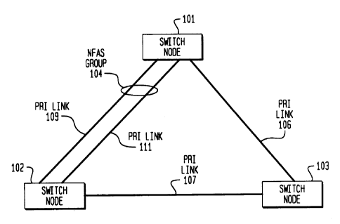
FIG. 1 shows a telecommunication switching system having a plurality
of switch nodes 101, 102, and 103. The switch nodes of FIG. 1 function as an
integrated system to provide telecommunication services. Switch nodes 101 and
102
are interconnected by NFAS group 104 that includes PRI link 109 and PRI link
111.
PRI links 109 and 111 can also be BRI links or NFAS group 104 can be a
combination of BRI and PRI links. One skilled in the art could readily
envision
other types of communication links being used. In addition, switch node 101 is
interconnected to switch node 103 via PRI link 106, and switch node 102 is
interconnected to switch node 103 via PRI link 107. The switch nodes of FIG. 1
are
arranged in a node hierarchy with switch node 101 being the highest switch
node of
the node hierarchy. The manner in which the node hierarchy initialization and
dialing plan initiationization are performed is described in detail in U. S.
Patent
5,386,466.
Each PRI link in NFAS group 104 comprises 24 channels. If a PRI link
is utilized by itself, then the 24 channels of the PRI link are designated as
follows:
channel 24 is designated as the signaling channel/D channel and is utilized to
handle
the ISDN messages which are exchanged by the switch nodes. In addition, data
calls
can be set up on other logical links of the D channel. The remaining 23
channels are
designated as B channels and can be utilized for voice or data information.
Within a
NFAS group, one of the PRI links is designated to carry the primary D channel,
such
as PRI link 109, and a second PRI link is designated to carry the secondary D
channel, such as PRI link 111. In both the primary and secondary PRI link, one
of
the 24 channels is designated as the D channel and the remaining 23 channels
can be
utilized for communicating voice or data information. In any additional PRI
links, in- -
the NFAS group, all 24 channels are utilized for the communication of voice
and
data information.
In accordance with the prior art which is the ISDN specification, if PRI
link 111 fails, switch nodes 101 and 102 abandon the active calls that were
being
communicated on B channels of PRI link 111. The U.S. patent application
entitled
"ISDN B Channel and Data Link Automatic Restoration", filed the same day as
the
present application, and assigned to the same assignee as the present
application,
discloses the following. If there are idle B channels in PRI link 109, switch
nodes 101 and 102 transfer the active calls from the failed PRI link 111 to
the idle B
channels on PRI link 109. In accordance with the invention of the present
application, if there are no idle channels in PRI link 109, switch nodes 101
and 102
establish a FRI link via switch node 103 over PRI links 106 and 107. The
active
CA 02213467 1997-08-20
-$-
calls on the failed PRI link 111 are transferred to the B channels of the FRI
link.
Note, that normally switch nodes 101 and 102 would be connected to switch
node 103 via NFAS groups and there would be multiple PRI links in each NFAS
group. Only one interconnecting PRI link is shown between switch nodes 101 and
$ 102 and switch node 103 for simplicity of description.
FIG. 2 illustrates the software architecture of the switch nodes of FIG. 1.
This architecture is based on the conventional OSI model modified to implement
the
ISDN protocol. Further modifications have been made to this model to
incorporate
the invention. Software layers 205 through 209 are described in U. S. Patent
5,386,466.
The principal function of physical layer 201 is to terminate physical
links. Specifically, physical layer 201 is responsive for maintaining physical
channels and for controlling physical sub-channels thereon. Physical layer 201
comprises a software portion and physical interfaces. Further, the software
portion
of physical layer 201 is responsible for the direct control of the physical
interface to
which physical links communicate PRI and BRI information terminate. Physical
layer 201 presents to link layer 212 physical sub-channels and physical
channel as
entities controllable by link layer 212. Since physical layer 201 is
terminating the
physical links, physical layer 201 determines when a D channel of the primary
PRI
link of a NFAS group has failed because of the lost of framing on the channels
of the
D channel.
The primary function of link layer 212 is to assure that the information
transmitted over a physical channel is recovered intact and in the correct
order. This
is accomplished using another layer of protocol (referred to as the physical
packet
protocol) which allows multiple communications paths -- commonly referred to
as -
logical links -- to be established on a given physical channel or a physical
sub-
channel communicating packetized data. These logical links are used to
identify and
process data being communicated between layer 212 and physical layer 201. In
ISDN Q.921, the protocol used is the LAPD packet protocol. Further, link layer
212
allows higher software layers to control physical layer 201 in an abstract
manner.
Link layer 212 uses a first layer of software protocol.
As seen in FIG. 2, link layer 212 is divided into link interface 202 and
link management 203. The reason for this division is set forth herein below.
It will
be helpful at this point to discuss the communication of ISDN signals over a D
channel to help readers who have only a rudimentary knowledge of the
communication of ISDN signals over a D channel. At link layer 212, a plurality
of
logical links is established on a D channel. Only one of these logical links
CA 02213467 1997-08-20
-6-
communicates ISDN control signals, and this logical link is referred to as a
logical D
channel (LDC). The LDC is identified by a logical D channel number (LDCN).
Link interface 202 does the majority of the functions performed by link
layer 212, including the establishment of logical links. Link management 203
identifies the various link interfaces for higher software layers. Further,
link
management 203 communicates information between the logical links and higher
software layers. In addition, link management 403 is responsive to a signal
from
physical layer 201 indicating that the primary D channel has lost framing to
switch
to the D channel of the secondary PRI link of a NFAS group.
Network layer 204 processes information communicated on the LDCs
and terminates the ISDN Q.931 protocol. Hence, this layer is responsible for
negotiating the utilization of system resources for the termination or
origination of
calls external to a switching node. The network layer controls the allocation
of
channels on an interface on which a call is being received or set up. In
addition,
network layer 204 determines the primary and secondary D channels of a NFAS
group. For example, if switch node 102 receives a call from switch node 101
via
PRI link 11 l, network layer 204 of switch node 102 negotiates with its peer
layer
(the corresponding network layer 204 in switch node 101) in order to obtain
allocation of a D channel in PRI link 111. This negotiation is carried out
using
standard ISDN Q.931 messages such as the call setup message via the LDC setup
on
the D channel of PRI link 109 (assuming that this is the primary PRI link of
NFAS
group 104). Greater detail on the manner in which network software layer 204
functions with respect to setting up calls is set forth in U. S. Patent
5,386,466.
FIG. 3 illustrates, in block diagram form, the software architecture of
FIG. 2 as implemented in switch nodes 101 and 102. Software layers 203 through
209 are implemented on the main processor of switch nodes 101 and 102 which is
node processors 310 and 301, respectively. Specifically, the software layers
down
through the link management portion of the link layer are realized by software
layers
denoted as 330 through 336 in node processor 310 and 340 through 346 in node
processor 301. The link interface portion of the link layer is implemented by
remote
angel 320 and software modules in processor 310 designated as local angel 302
and
VIM angel 311. In processor 301, the link interface portion is implemented as
software modules designated as local angel 304 and VIM angel 303.
The physical layer is jointly implemented by hardware and software.
Specifically, the hardware portion of the physical layer for switch node 101
is
implemented by interfaces 316 through 317 and interfaces 327 through 328. The
software portion of the physical layer is performed by local angel 302 and
remote
CA 02213467 1997-08-20
_7_
angel 320. The hardware portion of the physical layer for switch 102 is
implemented
by interfaces 305 through 307. The software portion of the physical layer is
performed by local angel 304.
Consider now the previous example in greater detail. When PRI
link 111 fails, this failure is detected by the physical layers in both switch
nodes 101
and 102. The physical layers report this to the link layers in both switch
nodes. The
link layers are responsive to the loss of PRI link 111 to send to the
interface
managers of the network layers in both switch nodes a MPH DEACTIVATE
indication that reports a channel is gone. This indication is transmitted for
each
active channel that is lost in PRI link 111. Since switch node 101 is the
highest
switch node of the node hierarchy, switch node 101 is considered to be the
network
switch node and the interface manager at network layer 331 responds to the
indication. Further information on the significance of the network switch node
is set
forth in U.S. Patent No. 5,386,466. As described in the previously referenced
copending application, if there are idle channels within NFAS group 104,
network
layer 331 communicates with network layer 341 to transfer the active B
channels in
failed PRI link 111 to the idle B channels of PRI link 109. In accordance with
the
present invention, if there are not enough idle B channels in PRI link 109,
network
layer 331 requests that VIM angel 311 establish a FRI link. VIM angel 311
relays
this request to VIM application 338. In the present example, VIM application
338
establishes FRI link 350 via PRI link 106, switching node 103, and PRI link
107.
The manner in which FRI link 350 is established by VIM application 338, VIM
angel 31 l, VIM application 348, and VIM angel 303 is set forth in detail in
U.S.
Patent No. 5,182,751. Advantageously, FRI link 350 is established with 23
B channels. -One skilled in the art could readily envision that FRI link 350
could be -
established with a different number of B channels. When FRI link 350 becomes
active, network layer 341 is responsive to a L3 DL establish indication for
FRI link
350 from link management layer 330 to commence the transfer of the active
calls
from failed PRI link 111 to FRI link 350. The L3 DL establish indication is
generated when the new FRI link becomes active. When network layer 331
requests
that VIM application 338 establish the FRI link, network layer 331 supplies
information indicating that the FRI link is to be connected to switching node
102. In
addition, network layers 331 and 341 add FRI link 350 to NFAS group 104.
Network layers 331 and 341 add FRI link 350 to NFAS group 104 automatically
upon receiving the L3 DL establish indication. If at a later point in time,
another
PRI link fails and there is insufficient idle channels in NFAS group 104, the
previously described procedure will be once again performed, and another FRI
link
CA 02213467 1997-08-20
_g_
will be established and added to NFAS group 104.
FIG. 4 illustrates the steps performed by a network layer when a
indication is received from the link management layer that a active channel
has been
lost. Block 401 shows that the process is initiated by receipt of a
MPH DEACTIVATE. Decision block 402 determines if there is a NFAS group to
the destination to which the active channel had been connected. If the answer
is no,
control is transferred to block 404. If the answer is yes, decision block 403
determines if there is an idle channel in the NFAS group. If the answer is no,
control
is transferred to block 404 which sends a request to the VIM angel for a FRI
link to
be set up. FIG. 5 describes the action taken when the FRI link is established.
After
execution of block 404, control is transferred to block 407 and the process is
terminated.
Returning to decision block 403, if the answer is yes, that there is an idle
channel within the NFAS group, control is transferred to block 406 which
transfers
the failed active channel to an idle channel of the NFAS group. After
execution of
block 406, control is transferred to block 407.
FIG. 5 illustrates the steps performed by a network layer upon being
informed that a new link has been established to a destination. The process is
started
by receipt of a L3 DL establish indication. Upon receipt of this indication,
decision
block 502 determines if there is already NFAS group to the destination. If the
answer is no, control is transferred to decision block 508 which determines if
there is
a single link to the destination. If the answer in decision block 508 is no,
control is
transferred to block 51 l, and the initialization of the link is handled in a
normal
manner. After execution of block 511, control is transferred to block 504. The
actions performed by blocks 504, 506, and 507 are described in the next
paragraph.
If the answer in decision block 508 is yes, block 509 creates a NFAS group
before
transferring control to block 504.
Returning to decision block 502, if there already is a NFAS group to the
destination, control is transferred to block 503 which adds the new link to
the
established NFAS group before transferring control to decision block 504.
Decision
block 504 determines if there are any active channels from a failed link which
have
not yet timed out. If the answer is no in decision block 504, control is
transferred to
block 507, and the process is terminated. If the answer is yes in decision
block 504,
block 506 proceeds to transfer each of the active channels from the failed
group to
the idle channels of the NFAS group before transfernng control to block 507.
There
are now idle channels in the NFAS group that resulted from the idle channels
of the
newly established link to the destination.