Note: Descriptions are shown in the official language in which they were submitted.
CA 02213474 1997-08-20
WO 96127406 PCTlIB96/OOI43
SLOWLY DI1~4TING DEVICE FOR THE URETHRA
.,
Technical Field
This invention relates generally to dilation devices for the: urethra and to
the
treatment of hypertrophy of the prostate gland. More specifically it relates
to novel
devices for slowly dilating obstructed portions of the urethra, »nd to
concomitant
methods for slowly dilating an obstructed portion of the urethra and for
treating benign
prostate hyperplasia (BPH).
Benign prostate hyperplasia is a condition which affects vvell over 5096 of
the
male population over 50 years of age. The treatment of BPH its a matter of
great
medical and commercial importance. On a worldwide basis, upwards of four
billion
dollars are spent annually in the treatment of this. condition.
Backctround p,rt
There are many devices, techniques and methods which are presently being
employed for treating BPH. Surgical treatment of hypertrophy of the prostate
has been
a routine procedure for many years. One method of such surgical treatment is
open
prostatectomy wherein the gland is totally or partially removed. Another
method of
surgical treatment is transurethral resection of tihe prostate (TUF3P).
However while
surgical treatment can bE effective it remains an extremely invasive:
procedure which is
debilitating, painful and often traumatic to the patient. Various
complications including
impotence, incontinence, bleeding, infection and:~ther undesirable problems
attendant
with such surgery can result. The need for less invasive procedures is
therefore of
considerable importance.
Among the less invasive procedures now being employed is that of using
catheters which are placed in the external opening of the urethra and into at
least the
obstructed portions of the urethra which allow the passage of urine from the
bladder
by way of the catheter lumen. These urinary catheters typically employ a
positioning
or retention balloon at the distal tip which, at the bladder neck, when
inflated, prevents
the expulsion of the catheter from the body. Illustrative of such positioning
balloon
catheters are those known in the art as Foley catheters.
It has also been proposed to utilize inflation balloons in addition to
positioning
balloons for the purpose of dilating obstructed portions of the urethra.
Illustrative of
such type balloons are those described in U.S.P. 4,932,958 to Reddy.
CA 02213474 1997-08-20
WO 96!27406 PCT/1896/00143
_2_
It has also been proposed to utilize heat in combination with such catheters
for
treating the enlarged portion of the prostate, such heat being provided by a
variety of x
means including the use of microwave or laser energy.
Again, while these methods and devices are useful, the search for even less
invasive devices and procedures continues. The need for devices and procedures
which will result in less pain and discomfort to the patient is of substantial
interest, as
is the desirability of providing means and devices which will provide for
longer term
patency of a dilated urethra, i.e. to effect a longer lasting result on
relieving the
obstruction in the urethra caused by the hypertrophied prostate gland. The
latter, due
to its resilient fibrous structure and large bulk tends to rebound after
treatment of the
obstructed urethra is completed, resulting in renewed obstruction.
It would be very desirable, therefore, to provide devices and methods for
treating
BPH which would be much less invasive and painful, and which would result in
dilated
urethras of longer patency.
Illustrative of a somewhat less invasive approach is found in the U.S.P.
4,762,128 to Rosenbluth. This patent discloses an expansion catheter having a
rapidly
expandable tubular stent associated therewith, which is adapted for
transurethral
insertion via the externai opening of the urethra and for placement within an
obstructed
region of the urethra! lumen caused by a hypertrophied prostate gland. Removal
of the
expansion catheter leaving in place an expanded tubular stent may result in
tong term
patency of the urethra! lumen. Though the stent is also adapted to be
removable from
the urethra, the intent of the device is to establish a long-term implant.
In U.S. Patent 5,163,952 to Froix there is disclosed an expandable stent for
use
in a lumen defined by a wall of a vessel, which illustratively is defined as
an arterial
vessel in the heart. The polymeric stent has a built-in elastic predetermined
diameter
and a memory of a diameter greater than the predetermined diameter which is
assumed
upon activation of a thermal activation point by the adsorption of heat by the
plastic,
adsorption of liquid by the plastic, or a change in the pH of the liquid
surrounding the
plastic.
In U.S. Patent 5,084,060 there is provided an apparatus for applying fluidic '
pressure to the inside of a body vessel during selected intervals to
incrementally
enlarge the lumen of the vessel.
CA 02213474 2000-09-07
77791-11
3
In U.S. Patent 4,660,560 to Klein there is disclosed
a method for treating obstructive prostatism which comprises
measuring the dist,~nce between the bladder neck and the veru
montanum, inserting a dilating catheter into the urethra, and
positioning the same, such as through the use of a positioning
balloon which can he located in the bladder neck.
Published PCT Patent Application WO 95/03848
discloses a method and device for slowly dilating the urethra
utilizing a hollow member permitting urination therethrough
from the bladder, and hydrophilic means associated therewith
which are capable of absorbing water and slowly swelling,
thereby dilating tine urethra.
Brief Disclosure of the Invention
In its broadest context, the present invention
provides a device for slowly dilating an obstructed portion of
a urethra which cornprise;~: a urinary catheter for insertion
into the urethra, ;paid catheter having a proximal portion and a
distal portion; a dilation means capable of expanding radially
outwardly, said means being disposed between said proximal and
distal portion and having a length of at least that of the
obstructed portion of the=_ urethra; pressure responsive means
which is capable of. sequE~ntially contracting under pressure;
conduit means which mai:nt~ains fluid communication between said
pressure responsive mean: and said dilation means, thereby
enabling fluid to f=low from said pressure responsive means,
when the latter is contracting under pressure, into said
dilation means to cause the latter to gradually expand radially
outwardly until di7_ation of the obstructed portion of the
urethra occurs to ~~ desired diameter and configuration; and
positioning means Located on said catheter for positioning
CA 02213474 2000-09-07
77791-11
3a
said device in the=_ urethra, such that said dilation means is
located in the ob;~tructed portion of the urethra.
The device provides a method for slowly dilating an
obstructed portion of a urethra by the sequential transfer of
fluid from pressure responsive means, which is capable of
expanding and coni=racti:ng, into dilation means which are
thereby radially expanded, the expanded dilation means thereby
impacting upon the obstructed portion of the urethra with
sufficient, and preferably constant, force to cause the latter
to gradually dilate to a desired diameter and configuration.
The dev=ice is useful for treating benign prostatic
hyperplasia by di=_ating an obstructed portion of the urethra
thereby relieving the obstruction caused by the hypertrophy of
the prostate gland.
1~~ The invE:ntion also provides a device for slowly
dilating an obstructed portion of a urethra which comprises: a
urinary catheter f=or in;~ertion into the prostatic urethra, said
catheter having a proximal portion and a distal portion; a
dilation balloon capable of expanding radially outwardly, said
2C~ balloon being disposed between said proximal and distal portion
and having a length of <~t least that of the obstructed portion
of the urethra; and pre:~sure responsive means in the form of an
expandable and contractible balloon which is disposed at or
near the distal portion of the catheter; said pressure
2~ responsive means rind dilation balloon being in fluid
communication through a lumen which enables fluid to flow from
said pressure responsive means, when the latter is contracting
under pressure, into the dilation balloon to cause the latter
to gradually expand rad_Lally outwardly at a rate of between
30 about 5 French and about: 20 French over a 24 hour period until
CA 02213474 2000-09-07
77791-11
3b
dilation of the ok>struct~ed portion of the urethra occurs to a
desired diameter and configuration; and wherein the lumen
includes a fluid resistor along the path thereof.
CA 02213474 1997-08-20
WO 96/27406 PCT/IB96/00143
-4-
In one embodiment of this invention, a single inflation/deflation lumen is
provided to effect initially the full inflation of the pressure responsive
means, and (less
than complete) inflation of the dilation means. In the latter case, the extent
of dilation
is thereby not adequate, or only partially adequate, to dilate the urethra in
the manner
desired. In this embodiment the subsequent contraction (and at least partial
deflation)
of the pressure responsive means results in the necessary full inflation of
the dilation
means thereby resulting in the dilation of the urethra.
In a preferred embodiment of this invention, the pressure responsive means is
disposed at or near the distal portion of the catheter and is capable of
initially being
inflated to a maximum extent due to the onset of fluid, from a single
inflation lumen or
conduit. This lumen can also act to transfer fluid to the dilation means upon
contraction of the pressure responsive means. However, it is also preferred
that the
flow of liquid from the pressure responsive means, when it is in a contracting
mode, be
effected through a separately disposed conduit or lumen, as hereinafter
described. In
this embodiment, the flow of fluid proceeds at a controlled rate, typically
through fluid
resistor means, which can be of the kind known in the art.
The slow or gradual dilation of the urethra has the significant advantage of
alleviating or lessening the discomfort felt by the patient which is the
concomitant effect
when rapid dilation of the urethra occurs, i.e. on the order of 10 minutes or
less, as is
the case with the usual dilation currently effected by most prior art devices.
In the
context of this invention, an expansion rate of between about 5 French and
about 20
French over a 24 hour period is desirable to effect the dilation of at least
the obstructed
portion of the urethra to a maximum or desired diameter and configuration.
In accordance with this invention, the dilation means, disposed on the
catheter
is usually in the form of a dilation balloon having an outer surface capable
of expanding
radially outwardly for a period of at least about 30 minutes. The length of
the dilation
balloon on the catheter should correspond to the length of at least that of
the
obstructed portion of the urethra. The inflation balloon can be elastic
without a defined
limit of intrinsic expansion or can also have a defined shape and an intrinsic
limit to
expansion.
The pressure responsive means can optionally be in the form of an expandable
and contractible balloon which can also act as a positioning balloon when
located in
the area of the bladder neck of the body. However, a separate positioning
balloon can
CA 02213474 1997-08-20
WO 96127406 PCTlIB96/OOI43
also be disposed as part of the device of this invention as, for example, in
the area of
the bulbous urethra. However, other suitable means can be employed to fix or
position
the device of this invention.
Another aspect of this invention is the fact that it can be adapted to remain
in
the urethra for extended periods of time before removal. Such an extended
presence
can be on the order of at least about 5 days t~~ about 30 days., the latter
being a
desirable upper limit because of clinical effi~;acy and patient comfort. As a
consequence of the long presence of the expanded device in the urethra, the
dilated
urethra) configuration will tend to remain in such configuration for an
extended period
of time, even after the device is removed. Up to 112-24 months or more is
likely before
obstruction of the prostatic urethra will occur again. This is a highly
desirable result of
this aspect of the invention. As stated above, in i;he prior means employed
for rapidly
dilating obstructed portions of the urethra, deformation of the urethra) wall
will often
have a relatively short effect on relieving the .obstruction of the prostatic
urethra
because the latter is caused by the continued pressure exerted b~y the
hypertrophied
prostate gland, due to the resilient viscoelastic nature of its tissue, and
because of
continued hypertrophy.
While the device of this invention can be in the form of a unitary catheter,
it is
also contemplated that the device can comprise a stent having the aforesaid
dilation
means and pressure responsive means thereon, vrhich can remain in the dilated
urethra
for the desired time, and a removable section for inserting the sten~t, which
can include
a filling tube for effecting the initial flow of fluid into the stent. Any
suitable attachable
means can be provided for removing a unitary catheter after deflation of both
the
dilation means and the pressure responsive means. If the catheter comprises a
stent
and a removable section, the latter is by its nature removable by the simple
act of
withdrawing the section after it is detached from the stent. The means for
removing the
stent from the dilated urethra can be accomplished by any means known in the
art,
such as the use of clamps or pull strings.
Further objects, features and advantages of the present invention will become
apparent from the detailed description of the drawings.
Brief Description of th~~ Drawincrs
Fig. 1 is a simplified sectional view of the relevant anatomy of a male body,
showing an obstructed urethra, an enlarged prosi:ate gland, a bladder, and a
schematic
CA 02213474 1997-08-20
WO 96/27406 PCT/IB96/00143
-6-
unexpanded dilation device of the subject invention, as hereinafter described,
which is
positioned just before insertion into the obstructed portion of the prostatic
urethra.
Fig. 2 is a sectional view of a portion of Fig. 1 depicting a portion of the
dilation
J
device, in a non-expanded state, implanted within the obstructed portion of
the urethra.
Pressure responsive means is shown distally disposed inside the bladder.
Fig. 3 is a sectional view of the device shown in Fig. 2, in an expanded
state,
and indicating the concomitant dilation of the prostatic urethra, wherein the
pressure
responsive means, though partially deflated, is acting as a positioning
balloon.
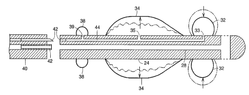
Fig. 4 is a schematic view of a dilation device of this invention, wherein the
pressure responsive means and dilation balloon are in fluid communication
through a
single lumen, the device further comprising a stent portion and a detachable
inserter.
Fig. 5 is a schematic view of a dilation device of this invention wherein the
pressure responsive means also serves as a positioning balloon, and a separate
lumen
provides further fluid communication between the dilation balloon and the
pressure
responsive/positioning balloon.
Detailed Disclosure of the Invention
In the drawings like reference numerals are utilized for like parts throughout
the
several views. In Fig. 1 there is illustrated, in simplified form, a urethra
10 having an
obstructed portion 12 about which is depicted an enlarged hypertrophied
prostate
gland 14, which inferentially is pressing inwardly on the obstructed portion
12. Also
shown is a bladder 16 having a neck 18 depending therefrom, and at the other
end of
the urethra is a penis 20. A dilation device 22 according to the subject
invention, which
will be hereinafter described, is shown in position to be inserted into the
urethra 10, the
device 22 comprising portion 24 having a length at least equal to that of the
obstructed
portion 12.
In Fig. 2 there is shown a simplified sectional view of the portion 24 when
placed
in the obstructed portion of the urethra. The portion 24 is depicted in an
unexpanded
mode. Extending through the portion 24 is a draining lumen 28 having a bladder
'
drainage port 30 in the distal portion of the device which communicates with
the
drainage lumen, for permitting the flow of urine therethrough, i.e., from the
bladder '
through the urethra and out of the penis. Protruding portion 26 can be
attached to
suitable means for insertion. The lumen 28 acts as a conduit having a diameter
sufficient to permit urine to flow therethrough. A pressure responsive
inflatable source
CA 02213474 1997-08-20
WO 96127406 PCT1~96100I43
_7_
32 is shown disposed in the distal portion of the F~ortion 24 which, when
secured in the
body, would usually be in the area of the bladder neck. Inflatable means 34,
which is
preferably in the form of a dilation balloon, is disposed along the outer
surface of the
portion 24 and has a length at least equal to that of the obstn~cted portion
of the
urethra.
The portion 24 of the device of the subject invention, wfierein the inflatable
means is in its unexpanded state, should be ofi a minimum diameter, including
the
pressure responsive means and dilation balloon, which would allow the device
22 to
be inserted into the penis and then into the ob:;tructed portion of the
urethra with a
minimum of discomfort. A suitable diameter in this regard should be about 20
to about
26 French. (1 French = 1/3 mm). The dilation balloon should be a material
capable
of expanding outwardly and radically so as to impact upon the obstructed
urethra, in
order to expand and dilate the obstructed portion 12 of the urethra 10 to a
predetermined diameter and (dilated) configuration.
In Fig. 3, the dilation balloon 34 of the dihition device of this invention is
shown
in an expanded, inflated state with outer surface 3fi impacting on thie
obstructed portion
of the urethra. The portion 12 of the urethra, formerly obstructed by the
hyperplasia of
the prostate gland, is now shown in a dilated configuration. The pressure
responsive
means or pressure source 32 is initially compleaely inflated but in the final
operable
mode of this embodiment wherein the urethra is inflated, the pressure
responsive
means 32 is only partially inflated; however, it remains sufficiently inflated
so that, in this
embodiment, it also acts as a positioning balloon, located at the bladder
neck.
In Fig. 4 there is shown a schematic cross-sectional view of another typical
device of this invention. As depicted therein, a pressure source 32 is
disposed in the
distal portion of the device, on the portion 24, which is in the form of a
stent, and a
dilation envelope 34, which is preferably a balloon such as is normally used
in this art,
is disposed proximal to but not abutting with thE~ pressure souraa. Downstream
from
the dilation balloon, but in this embodiment still a part of the stent, is a
location or
positioning balloon 38. In this embodiment, the pressure sources 32 is adapted
to be
disposed in the bladder while the positioning balloon 38 is adapled to be
disposed in
the area of the bulbous urethra. It is also possible in this embodiment for
the pressure
source to act as an additional positioning mean >, which will aid in retaining
the device
within the urethra. The dilation balloon is of a length of at least that of
the obstructed
CA 02213474 1997-08-20
WO 96!27406 PCT/IB96/00143
-8-
portion of the urethra. Also shown in this figure is an attaching inserter
member 40
which preferably can be detachable, leaving the stent in the urethra. However,
optionally, it is to be understood that the inserter and stent can remain
undetached, i.e.,
the device thereby functioning as a catheter. Means 42, illustratively in the
form a
needle and septum, for attaching or detaching the catheter, can also be
provided.
As stated above, draining lumen 28 extends through the device 22. Location
balloon 38, dilation balloon 34 and pressure source 32 are also in fluid
communication
with each other through lumen 44 which extends through device 22. Port 39
permits
the flow of fluid into location balloon 38. Ports 35 and 33 permit the flow of
fluid into
the dilation balloon 34 and pressure source 32 respectively.
In operation, the passage of fluid from outside the penis through lumen 44 is
controlled so that the positioning balloon 38 and the pressure source 32 are
fully
inflated, but in the context of this invention, the dilation balloon 34 is
initially only
partially inflated, i.e., to an extent less than that needed to impact with
sufficient force
to dilate the obstructed portion of the urethra. In a preferred mode of
operation, when
pressure source 32 contracts due to the pressure differential between that of
the
pressure source and the pressure exerted on the dilation balloon by the
hypertrophied
prostate, fluid will flow at a predetermined rate from the pressure source
into the dilation
balloon so as to slowly and gradually expand the latter to the extent
necessary for it to
impact with sufficient force to dilate the obstructed portion of the urethra.
The rate of
this flow can also be determined by the geometry and elastic modulus of the
pressure
balloon, which will contrast to the resistance of the prostate tissue
surrounding the
dilation balloon.
In Fig. 5 there is shown an embodiment of this invention in which the pressure
responsive balloon 32 also serves as a positioning balloon which would be
adapted to
be located in the bladder neck. Also shown in this figure is the single lumen
44 which
is in fluid communication with the pressure responsive balloon 32 and serves
to initially
fully inflate the pressure responsive balloon.
However, in this embodiment, separate lumen 46 provides for the passage of
fluid from the contracting pressure balloon 32 into the dilation balloon 34,
to effect the
desired expansion of the latter. Lumen 46, as shown, continues to the end of
the stent.
Also shown is a fluid resistor 48 (which can be of a type well known in the
art) which
acts to control the rate of passage of fluid from pressure source 32 to
dilation balloon
CA 02213474 1997-08-20
W O 96127406 PCT1IB96/OOI43
_g
34 to enable the latter to expand gradually and sllowly in accordance with the
practice
of this invention. The viscosity of the fluid further controls the rate of
flow. Port 50
allows fluid to enter the dilation balloon from lumen 46. When def9ation of
the stent is
required in order to remove the stent, a drainage plug 52 can be utilized. A
suitable
plug is described in U.S. patent 5,112,306.
It is also to be understood that within the context of thia invention that the
pressure responsive means can optionally be disposed outside of the body in
the form
of, for example, a syringe pump or pump bulb. When such mean;: are employed
fluid
can be transferred into the dilation means by applying suitable F>ressure in
carefully
monitored amounts to thereby slowly dilate the dilation means.
As stated above, the diameter of the unexpended devices of this invention
should be on the order of between about 20 and 2~bout 26 French. Generally
speaking,
diameters of less than about 20 French will not permit adequate urination in
combination with desired dilation, while the insertion into the meatus of the
penis prior
to insertion into an obstructed prostatic urethra of an unexpended device
having a
diameter of more than about 26 French will usually be too painful ifor a
patient. It thus
follows that the diameter of the lumens of the devices of this invention
should be fixed
within the tolerable limits of the diametral range of the unexpended device,
preferably
on or about 20 French.
The gradual, slow dilation of the dilation balloon should occur over a period
of
at least 30 minutes, and preferably over a much I~~nger period, a dilation
which occurs
at a rate of about 5 French per 20 hour period being particularly desirable.
Thus if a
dilated stent of 70 French is desired, and the initial) stent diameter was
about 20 French,
the slow dilation could take as long as 9 or 10 days. A long expansion period
may also
result in a longer patency for the resulting dilation. In this regard, the
device of the
subject invention is adapted to remain in the urethra for periods on the order
of seven
days to 30 days, the latter being a practical upper limit for retention in the
urethra for
biocompatible reasons, such as possible urinary tract infection, incireased
inflammation
or bacterially based prostatitis.
For reasons which are not completely known, when the device of this invention
is removed, the dilated urethra will tend to remain in its dilated
configuration for a
period on the order of about 12 to about 24 months, or longer, i.e., the
patency of the
urethra) lumen or canal will tend to remain in its dilated state. It is
believed that the
CA 02213474 1997-08-20
WD 96/27406 PCT/IB96/00143
-10-
slow dilation causes pressure necrosis of the tissue with fibrous collagen
deposition
within the parenchyma of the prostate. The fibrous tissue is not
physiologically active
thus reducing the ability of the prostate to contract. This scarring of the
gland is much
like that which occurs in the myocardium after infarction. '
It is apparent that other modifications and variations besides those
specifically
mentioned herein may be made in the devices described herein and depicted in
the
accompanying drawings without departing from the concept of the present
invention.