Note: Descriptions are shown in the official language in which they were submitted.
CA 02213501 1997-08-20
WO96/2~10 ~1/~B_~0378
D~S~LA~ENT MEA~ ~ K I - - ~ ~ 1 APP~Ara~ AND M~T~OD
The pre~ent invention relates ko an apparatus and
method ~or measuring the relat~e dispi~c~ - t o~ an object
with respect to a re~erence po9ition.
In many areas it i~ ext~emely deRirable to ~e able to
precisely mea~ure a small displacement of an object
relatiYe to some re~erence po5ition One area in which
thi~ technique i8 particularly applicable i5 in deter~;nin~
the relative mo~ement of parts of large engineering
~tructure~, for ~y~mr1e, br~dge~ and their supports. It i8
o~ten the ca~e that the bulk o~ the ~easurement apparatu~
cannot be mounted on a surface which can be guaranteed to
be fixed wit~ respec~ to any of the moving parts of
interes~.
A econd area o~ a~licatior ~s ~.. t..e de-ermination
of the b~n~l ng of a gun ~arrel, and in particular t~e sun
barral of a tank, in order t,o ensure highly accur~te firing
of the gun. ~n~; n~ of a gun barrel can be caused by a
number o~ facto~s including thermal effects resulting from
f1ring of the gun andfor w~th~r conditions, h~k~c~ in
t~e gun mounting following each firing, and vibration due
to tank mo~ion. W~ilst it is pos~ible to reduce the
ef~ects o~ barrel h~n~1~g by phy~ically Ytabili~ing the
barrel, it is not pos6ible to completely eliminate the
problem. 3~fort~ have therefore been made to provide
systems for determ~ the extent of barrel ~ g 30
that the degree o~ bendi~g can be e~r~nR~ted for when the
gun i5 belng aim~d.
There is described in GB 1,587,7~4 apparatu~ for
correctin~ sighting errors in a tank gun barrel arising
~rom barrel b~n~;n~ The sy~tem cuu-~lise~ a light source
and an ad~acent detector, both fixed to ehe breech end o~
the gun barrel, or to the tank turret, and a mirror ~ixed
at or near the muzz~e end of the gun barrel. A light beam
from the light 60urce i8 directed onto th~ ~irror which
reflects th~ light beam back to the li~ht detector Any
angular di~placement o~ the barrel m~zzle relative to the
breech end o~ the barrel causes the returning light beam to
CA 02213501 1997-08-20
WO g6J:Z6410 PCrlGl~g~0378
be moved across, or off, the liyht detector. The extent of
any anyular displ~com~nt can t~eref~re be e~t;m~t~d ~y
monitoring the output o~ the light detector. Other ~y~tems
are known which project a colli~ated b~am o~ light fro~ ehe
~ource to ~he ~uzzle mirror and thence b~ck to the
detector.
A problem with ~te~ such as that described in
G~ 1,5~7,714, and ~imilar 8y8tems co,-~o--ly known a~ muzzle
reference systems ~M~ZS), i8 that beam deflection can occur
due to ~actor~ other than displacem~nt o~ ~he barrel
muzzle. For exampIe, ~ v~---e--t o~ optical ~ nts in the
tran~mittin~ or reoelvin~ optical sYstem~ can cause such
~eam de~lection. In ~ddition, non~ o~rity in the light
detector itsel~, or in other co~r~nt~ of the detection
circuitry, c~n erroneou~ly indicate barrel displacement.
These ~ Ol~ are inevita~ly translated into misali~nmo~ of
the gun barrel when the barrel is being aimed. Significant
targeting errors can arise ~ro~ hon~ n~ of the gun barrel
by even a ~ew tens o~ micro-ra~ ~n~ and the known muzzle
re~erence 3y6tem6 are not capable of re~olving he~din~
measu~l ~ ts with this degree o~ accura~y.
It is an object o~ the pre~ent invent~on to overcome
or at le~se ~i~igate cer~ain o~ the disadvantages o~ kn~wn
apparatus and methods for determining relative object
diRplacement.
In particu~ar, it i~ an object o~ the preRent
in~ention to prov~de an automatic m~zzle reference ~en~or
~AMRs) system ~or measuring the angular disp}acement of a
gun barrel muzzle w~th re~pect to the breech end o~ the
b~rrel whil~t ~u~antially eliminat~ng error~ resulting
~rom tran~mitting and receiving optics and circuitry.
Accoxding to a first aspect o~ the present in~ention
there i~ provided apparatu~ ~or mea~ing the displacement
of a ~irst object rel~ive to a ~cond obJ~ct, the
apparatus comprising elec~rom-~net~c radiation source and
detection mean~, fir3t an~ second reflect~on ~ean~ fixed to
the firet and ~econd objec~ respectively, radiation guide
CA 02213501 1997-08-20
WO 96J26~10 ~ 5 ~,'C ' '~
means forming ~irst and 3econd ~h~nnels for direotlng
radiation from the so~rce mean~ respecti~e~y on~o the first
and ~econd reflection means and for directing the
re~pective reflected ~eams onto t~e detection ~ean~, the
det~ction ~ean~ comprising a deteetion sur~ace arranged to
provide 3ignals indlcative of ~he positions on the
detection surface where the reflected be~m~ o~ the ~irst
and ~econd ch~"n~ls are incident, and evaluation m~an~
coupled to receive said signal~ and by di~~erential
measu~ement to calcul~te there~rom a measure of the
di~pl~cemon~ of t~e fir~t object rela~ive to the second
object.
~ he provi~ion o~ a differential mea~urement between
the firs~ and second ~h~"n~ls ~llow~ for the compensation
o~ o~l~et errors arising in Co~ron~onts f~ O~ to the ~irst
and second ~h~nn~lq, for example the detection meanq.
The firs~ and second re~lect~on means referred to
above may be any suitable means for redirecting radiation
in~ident thereon, eg mirror~ or pri~m arranyement3.
A particularly ~uitable ~o~m of detect~on sur~ace is
a later~l effect photodiode arranged to determine the
po~ition o~ the centroid o~ an incident radiation beam.
Thi~ type of detection surface will generally require that
the 30urce means be arransed to sequentially generate firqt
~nd ~econd beams for direction to the fir~t and second
reflection mean~ respectively such that the detector
surface may di~tingui~h between them and provide reapecti~e
sequent~al ~ignals to the evaluation means. In thi3 ~se
the evaluation mean~ comp~i~es a calculation or arithmetic
unit and a data ~torage unit.
Another ~uitable form of detection ~urface is pravided
by a TV camera ~hich may be of the ~idicon or CCD type and
whlch recordq the position of the or each incident light
beam. With this type of detectlon ~ur~ace the source mean~
may simultaneou~ly generate the first and ~econd beams if
~heir incid~c~ on the TV camer~ are indi~idually
di~tinguishable ~eg by physical -~eparation or by ~hape).
CA 02213501 1997-08-20
WO ~n~lo ~ 37
The evaluat~on mean~ in this case cc...~ises a storage unit
and an automatic classification and tracking syRtem
together ~ith a calculation or ar~thmetic unit.
Preferably, the Rource means comprise a plurality of
discrete saurces which ~re fixed relative to eac~ other.
T~e detector means may also comprise a plurality o~
discrete detectian sur~aces which are fixed relative to
each other.
Preferably, the f~rst beam and the second bea~ pa~s
through several c~n optical component~. ~or example,
where the guide means for directing the f~rst beam toward~
the fir-~t reflectio~ mean~ compri~es a colli~atin~ lens,
the second bea~ is al~o di~ected through this collimating
len~. gi~ilarly, where the f~rst beam is ~ccused onto ~e
deteetion ~urface by a lens, the second beam is also
arranged to pass through this len~. Th~s arrange~e~t
enables variation~ ari6ing from the ..-vv~...cnt o~ the
c311imating and ~ocusing lense~ which are c~"~ optlcal
~.L~ ent~, to be compensated for. Preferably, co...~o.,ents
which are not ~_. ~ between t~e t~o channel~ a~e
inherently ~table. For example, a corner-cube may ~e used
to reverse the direc~ion of a beam, the cube being
inherently subst~n~;~lly in~ensitive to it~ preci6e
orientation
Preferably, the radiatio~ source mean~ is axranged to
generate a third beam of ele~tromagnetic radiation, the
third beam being directed to the detection mean3 by the
same guide mean~ used to direct the second beam, the second
and third beam~ being arranged to be incident ~pon the
deteceion surface at nor;n~lly fixed, spaced apart
locations whereby a change in the mea~ured ~epara~ion of
the second and third beams at the de~ection 8u~f ace enables
the cal~ulation of rela~ive di~placement to be compenRated
~or variation~ ~om an init~al value of the system~s
sensitivity (gain).
Preferably, t~e de~ec~ion mean~ i~ capable of
measuring di6placements in two sub~tantially orthogonal
CA 02213501 1997-08-20
WO9~6410
axe~, contai~ed within the plane o~ ~he detection surface,
and the ev~luation means i8 a~le to re~olve the def~lection
or displacement of the fir~t o~ject relac~e to the Recond
object into any o~ a number o~ co-ordinate systems.
The detection 6ur~ace may, ~or example, be a two axis
continuous sensing ~uper-~i n~ lateral ef fect photodiode.
In a preferred embodiment of the pre~ent i~entinn,
the source means o~ elect~or~ ne~ic radiation compri~es
discrete optical ~ibres coupled to ~eparate laeer diodes
which can be energi~ed in turn to permit a detection
sur~ace, which respond~ onIy to the centroid of the total
incident radiation, to di~criminate becween them
Mechanical ~cre~rl; ng is provided to p~ e~t radiation from
any fi~re from tra~ersing an incorrect chann~l. A
colli~ating lens ~or the fibre~, a focu~ing len~ and a two-
axi6 conti~u~ po~ition ~en~it~e detector are c~ o~ to
all ~h~nnel~ The fir6t c~nnel which comprise~ the ~irst
re~lection means addit;o~lly ~omprises a pair o~ steering
~edges and a focuR ad~ustment lens in the transmission pat~
and a second pair o~ ~teering wedges and focus ad~ustment
lens in the reception path. ~he f~r~t ~eflection mean~
oomprises a plane mirror. The second ~h~nn~l which
co~prises the second reflection means additionall~
compri~es a trunc~ted corner c~be in the transmi3sion path,
a ~econd truncated corner oube in the reception parh, and
a 'W~ prism which forms the second re~lection means.
Ac~ording to a ~econd aspect o~ the pr~sent lnvention
there is provided apparatus for me~surin~ the displacements
o~ firct and second o~ject~ relati~e ~o a d~tum o~ the
apparatuR, the apparatu~ c~ ising a 60urce o~
electromagnetic radiation and an electro~agnetic radiation
dete~ion means, both means being ~ixed relative to said
d~tum, wherein di~placement of a beam of radiation fr~ the
source acro~s the detectlon mean~ is me~surable by the
detect~on mean~i, an e~raluat~on mean-~ coupled to the
detection means ~or calculating the tr~e displ~ rller~t
rela~cive ~o the appara~us datum of the source beam based on
CA 02213501 1997-08-20
WO9~10 ~ J~37
ehe said measured displacement, the app~ratuc al~o
eomprising a main r~nn~l having a fir~t reflection ~eans
arranged to be fixed relative to the first ob~ect, means
for directing a main ~eam of electromagnetic radiation ~rom
the source onto the firfit refle~ting means, the first
reflection ~ean~ being arranged to reflect radiation ~rom
the ;~Gi~ent main beam onto the detection means, wherein
displacement of the first objoct recults in a corres~o~A;~
disp~ace~ent of the reflected main beam acro~s the
detection means, means for causing the detection means to
~ refipond only to radiation ~rom ~he source traversing the
~n Ch~ ~pra- a~u~ Lu~ r comprlsing a re~erence
~h~nn~l havi~g a second xe~lection ~ean6 arranged to be
fixed relative to the ~econd object, means ~or dir~c~inq a
refere~ce ~eam of electromagnetic radiation from the source
onto the second re~lection mean~, the second ~e~lection
means bei~g arranged to reflect radiation fro~ the ;n~id~nt
reference beam onto the detection ~eans, wherein
displ~ t of the second o~ect re~ult~ in a
correfipo~; n~ di3pl ~re~nt of the re~lected referenoe beam
acro s t~e detection means, meanc for causing the detection
means to respond only to radiation from the ~ource
trave~sing the reference ch~n~l, the cal~ulation means
being ~urther arranged to provide an output indicative o~
displac~nt dl~ference between the first and second
objects.
According to the third ~spect o~ the pre~ent invention
there 1~ provided an automatic muzzle reference sen~or
~ystem compri6~ng apparatus according to the a~ove first or
~econd aspect of the invent~on, wherein the fir~t object is
at or near the mu~zle of a gun barrel and the ~econd o~ect
and is at or near the breech end of the gun barrel.
Accarding to a fourth acpect o~ the present invention
t~ere i5 provided a method o~ measu~ing the di~place~ent of
a ~irRt o~ect relative to a second object, the ~ethod
compri~ing d~recting a beam o~ electro~gnetic ~adiation
~rom a source towards a reflection mean~ fixed relative to
CA 02213501 1997-08-20
wo9~ P~J~9~003~8
t~e first object, detecting displacement o~ the first
~eflected beam by way of a detec~or,.generating a second
beam of eleccromagnetic radiation and directing it towards
a second re~lection mean~ fixed relative to the ~econd
object, detecting di~place~ent o~ the second re~lected beam
by way of 6aid detector, and calculating ~he relative
di~placement of the first and second ohjects ~rom the two
detected beam displacem~t~.
The above method by virtue of dif~erential mea~urement
ena~les the esti~ation of said relative displacement to be
compens~te~ for elLo~~~ which arise equally in ~oth of the
detected be~m d~ splacement~.
For a better underst~n~ing of the pre~ent invention
and in order to show how the s~me ~ay be carried ~n~o
effec~ reference will now be made, by way of example, to
he A ~ - _ nying drallrings, in which:
Figure 1 8ho~s an ~t~matiC muz~le reference sen60r
9y8tem att~h~ to the gun barrel of a tank;
F~gure 2 shown in detail the optical ce~ nt~ o~ the
auto~atic muzzle reference ~yste~ of Figure 1;
Figure 3 shows a plan view of a photodetector o~ the
~yQte~ of Figures 1 and 2 showing the positions at which a
main bea~ and two reference beams are ; nci ~nt; and
Figure 4 show~ a displacement re~erence 3y~tem ~or u~e
in detecting mo~ement o~ a bridge structure; ~nd
Figure S show~ in de~ail the optlcal components of the
sy~tem of Figure 4.
~ here i~ ~hown in Figure 1 a gun barrel 1 which
extends ~rom the tur~et 2 of a tank. ~he barrel is able to
~ecoil through a protective ~antlet ~ which otherwi~e
elevates and depresses in harmony with ~he gun barrel. The
tank is pro~ided with an ~ueomatic muzzle re~erence sensor
~AXRS) syste~ 4 which is arranged to provide an accurate
indication of muzzle deflection, due to ~en~in~ o~ che
barrel, to an aimi~g computer ~not ~hown in F~gure 1~ on-
board the tank. ~he AMRS sy~tcm campri~es a ~ir~t
reflection means in the fo~m of a mirror 5 which is rigidly
CA 02213501 1997-08-20
WOsU~10 PCT/GBg6~378
at~ch~ to the muzzle 6 at the end of the gun barrel l.
At the oppo~ite end o~ the gun barrel and rigidly fixed to
the gun mantlet 3 there is a sècond r~e~lection means in the
~orm of a prism 2~. A hou~in5 7 containing an optical
radiation ~ource, an adjacent detector arrangement and
transmit and roceive optics i~ provided at the breech end,
conveniently adjacent the ~antlet 3. As with ~o-1v~ ional
AMRS ~ystem5, a beam of light 8 generated by the light
source is directed along t~e length of the gun barrel 80 a~
to be inc$dent on t~e mirror 5 and to be reflected thereby
back towards the detector arrangement. ~$ght incident on
the detector a~ranqement cau~e~ ~n ~ t~ p.~
to be produced ~hich varies as the reflected bea~ mo~es
acro6~ the detection ~urf~ce, for example due to barrel
bendin~. '
In addition, the AMRS sy~tem 4 in accordance w~th the
pre~ent invention is provided wit~ an internal reference
~nn~l to enable d~ta transm~tted to the ~;min~ computer
to be compensated f or changes i~ the detector output which
ari~e from factors ot~er than barrel h~n~i ng, f or example
~.~ov~ ant o~ co.~ o~L~o~nts of the tr~n~ sion and~or
receiving optics. The u~e of 8uch a ~e~erence rh~nnel has
previously not been conYidered.
Figure 2 shows in more detail t~e optical ~ ,v~n~s
which comprise the AMRS sy~em 4 ~thc diagram is compres~ed
in the longit-2~i n~l direction fo~ clarity) and ill~strate~
a main and rcference mea~urement ch~n~e1. The active
c-G,~ ents of the Gy~te~ are rigldly secured within the
hou~ing 7 to ~ens~bly ~nimi~e errors arising from
vibration and r~lative ..,o~...e..t.
The housing 7 ~nt~nR t~ree light ~ources 9,lO,ll,
sec~red to a baseplate 12 in the focal plane of a CG~ -.0
collimating lens 13, and which are provided by re~pective
optical fibre~ and as~ociated laRer diodes. At any one
ti~e, only a singl~ one of the ligh~ sources is illuminated
by its laser as will be de3cri~ed hereinafte~. Mec~anical
baf~les tnot gho~nJ ~re prov$ded to prcvent light from the
CA 02213501 1997-08-20
Wa g6~2~410 PCTlr~-6J0~78
main ~h~nn~l source 9 reaching the detector ~rrangement via
the refere~ce ~hannel path, and light ~rom the re~erence
ch~nnel ~ources 10,11 reaching the detector ar~angement via
the main ch~nn~ path.
A first of the light sources 9 is arra~ed tc pro~ide
a main light be~m 14 which i~ directed by tran-cmitting
optic~ ~o as to be incident on the mi~ror 5, which
pre~era~ly i~ a plane mirror, mounted at the muzzle end of
the barrel. The main beam iB directed by the colli~ating
len~ 13, a pair of adju~table steering wedge8 15a,15b, and
a focu~ ad~ustment len~ 15. The ~eam is reflec~ed by the
muzzle mounted mirror 5 and is directed b~ receivina or~t~lcs
back toward the breech end of the ~arrel ~o as to be
incident upon the detector arran~ement which compri~es a
photodetector 17 connected ~o an e~al~a~ion means 18.
The reflected beam 14 passes through a second focu~
ad~u~tment lens 20, a se~ond pair o~ ~teering wedges
19a,19b, and a lsns 21 which focu~e~ the ~eam to a ~ine
spot, which iB an image o~ the light source 9, on the
sur~ace of the photodetector 17. It will ~e appreciated
from Figure~ 1 and 2 that any di~pl~ ent o~ the mirror ~
will cause the spot focu~ed onto the photodetector 17 to
move acro~ the photodetector surface and, i~ the angular
di~plA~m~nt o~ the mirror 5 is great enough. to move off
the 6u~face of the photodetector 17. It ~ill al~o be
appreciated that, i~ the mirror 5 i~ a plane mirror, the
focu~ adjustment len6e~ 16, 20 may no~ be required and the
focu~ed -~pot w~ll move acrosC~ the pho~odetector surf~ace in
response only to angular displacement o~ the mirror 5.
The se~ond and third light 60urces 10,11 provide a
pair or refer~nce beams 22,23 which are directed to paes
through an edge region o~ the collimating len~ 13 of the
transmittin~ optics. A corner cube 24 i~ situated bF~hin~
the cdge of the collimating len~ 13 and i8 arr;~nged ~co
receive the two re~erence ~eam~ tr~nsmitted through the
collimating lens 13 and to reflect them back towards the
breech end of the hou~in~ 7. ~he~e reflected bea~ 22,23
-
CA 02213501 1997-08-20
W09~n6410 r ~/~B~f~0~7
pa~s throu~h a window 25 in the housing 7 and are incident
and are inciden~ upon the prism 26 whic~ preferabl~ i~ a
'W' prism 80 ~at the reference beams undergo three
refle~t$on~ and transver8e di3placement before being
directed once more back towards ~he muzzle end to a
truncated corner cube 27. This ~è~ond co~ner cube 27
reflects the two re~erence beam~ 22,~3 once more so that
- they are directed to pass throug~ an edge region o_ ehe
facu3ing len~ 21 hefore being incident upon the 6urfa~e o~
the photodetectox 17 and forming rcspecti~e image~ o~ the
light ~o~rce~ 10,11. The 'W' prism 26 is rigidly ~ecured
to and in close ~ontact with a m~unting inter~ace 23 of the
gun mantlet 3.
The ~omhin~ion of the two corner cubes 24,27, whi~h,
fD~ example, may be or tne ~olid gla~ truncated type and
the 'W' pri~ 26 provide the ne~ 7~y transver~e shift of
the reference beams 22,23 w~ilst allowing ~he beam~ to p~s~
through the collimating lens 13 and the focus~ng lens 21 of
the transmitting and receivin~ cp~ics respecti~ely. ~n
addition, th~ corner ~ubes 24, 27 and the prism 26 are
inherently stable ~ ~L,ents and the reflection8 within the
corner cu~es 24,27 and two of the reflections within the
'W~ prism 26 are ~elf-compensating for ~ nt tilt,
en~uring that the re~rence beam6 22,23 are not a~ected by
such d$splacement~, and in particula~ tran6verse
displ~c~m~nt6 of comp~nts 2g,26,27 which do not effect
the ma~n beam. Such displacements do not af~ect the main
beam 14 becau-~e it does not tra~er~e th~se co..~y~.Lent~, If
~uch displacements were presen~ they would lead to
uncompensated error~ in ~he diffe~nti~l di~pl~cemont
measurement. The thlrd ref lection ~n the 't~' prism i8 ~rom
a ~urf ace whi~h acts as a plane ref erence mirror
effecti~ely in contact with the mantlet 3. Similaxly, the
s~_ering wedses lsa~l5b~l9a~l9h and the weak focus
adj~tment len~e~ 1~,20 ti~ present) in the path o~ th~
main beam 14 are ~ery stable ~l rJv~lont~ ensurin~ that the
main beam 14 iB not a~ected by diç:placemes~t~ which do not
-
CA 02213501 1997-08-20
WO~6~641U ~ v~ 0378
11
a~ect the re~erence beam~ 22,23.
All o~ the optical co~ro~snts o~ the AM~S ~y~te~ use
gla~s type~ which have been chosen to co~pensate ~or
change~ in ~ocu~ with ambient temperat~re, which changes
arise mainly due to ~YrA~ion o~ the cho~en housing
material, Precise focusing is neces~ary, when high
acc~racy is de~ired, to avoid errors due to the par~llax
effec~ ~aused by variable Yignetting of the main beam 14
which may oc~ur due to a large de~lection of the ~eam by
the muzzle mirror 5 andJor partial obscuration due to, for
example, mud on the mir~or 5 whioh is an external
c~-~L)~ t. For the ~ame re~nn~, the len~ optic~l
aberration~ mus~ be highly corrected acros8 the aperture.
The~e e~fects do not normally im~r or. ~he r~rence
~h~nn~l ~ due to the fixed geometry o~ the~e ch~nel~
There is shown in Figure 3 a pl an view of the
pre~erred photodetector 1~- of the AMRg qy~tem. The
photodetector 17 ~or example is a lateral effect photod~ode
o~ the two-axis continuou~ type in which the signal photo-
~ t, which is pru~o~Lional ~o the total 3ignal poweri~ri ~nt upon it, i~ distri~uted among two orthogonal pair~
o~ signal term;nal~q ~denoted x+, x-, y+, ~-~ in a m~n~e~
dependent upon the po~ition of the centroid of the tctal
inoident energy. The terminal~ (x+, x- or y~, y-) are
a~sociated with po~iti~e and nega~iYe directions along
respec~ive orthogonal mea-~urement axes x, y relative to the
centre of the body of the photodetector.
The ~utput ~ignal~ of the four ter~in~l~ o~ the
photodetector 17 are comblned by the e~aluation means 18
(Figure 2), which o~ es a calculation or arithmetic
unit and a data ~torage unit, to determine the poRition o~
~he centroid o~ an in~dent light ~eam. For example,
Figure 3 show~ the po~ition o~ the centroid CM ~f a main
bcam ~pot M in~ident on th~ photodetector and al~o typical
po6it~ons o~ the t~o reference beam ~pots and their
re~pect~e ce~tro~ds, generally la~el}ed Rl and R~. With
the ori~in o~ the xy co-ord~nate system ~as indicated in
CA 02213501 1997-08-20
W~9GY6410 }~
12
Figure 3) being located at the centre o~ thc photodetector
17, the x co-ordinate Q~ ahy centroid is determined by the
eq~ation:
X = ~ ix.~ - i X ) / ( lX+ ' iX- )
an~ the y co-ordin~te is determined by t~e equation:
y = tiyl - iy_) t ~iyl I iy_) (2,
wh~re ix~, lx , iy~, and iy are the true ~ignal current~,
corrected for backgrou~d illumination and dark current
effects, output by rhe photodetector terminals and ehe
sub~cr~pts indicate the ~articular photodetector terminal
as described abo~e. In this type of detector t~e ent~re
photo-electrically generat~d current i~ (ix~ I ix_) and t~is
is equal to ~iy~ I iy_) but on the x-axis the location of
the centroid determines the distribut~n of rurren~ ~e~ween
i~ and ix_ Similarly for the y-axls and the CurreAts
iy~ and iy . The ~en~m1 ~tors in equat~on~ ~1) and (2)
normali~ the xy co-ordinate~ and gu~tantially el-~in~te
the e~fects o~ ~ntensity variation8 ~.n any l~ght source
9,10,11.
Since the detector 17 responds only to t~e centroid of
the total ~n~ nt ene~gy, it i~ nece~sary that two or ~ore
light ~o~rce images are not pre~ent 6imultaneously on ~he
deteotor. To t~is end, the source~ 9,10,11 are ~lluminated
~equentially, and individual synchronised mea~urement~ are
made for each ~ource ~ollowin~ which the separate
measurement~ are normali~ed u~ing equation~ (1) and 12)
above. A period with no souXce energ~E~ed i~; also provided
to allow co~r~n~tions to be achieved as ~escribed below.
For high accuracy, it is important that the photo-
current6 uaed ~n equat~on~ 1 and 2, or the amplifier
output~ which re~re~ent them, do AOt include contribution~
~ro~ background i~luminatlon, dark ~urrent, or from gain
di~erence~ in respective photodetector term~nal amplifier~
~not ~hown in the Figures). It is usual ~o employ
tran~imr~Rn~e preampli~rs wh~ch convert current dire~tly
i~to output vol~age and which have low 1nput and output
impedance~, with one or more ~ub~equent a~pliflcation
CA 02213501 1997-08-20
WO9~410 PCT~GB96~0378
13
stages c~nn~cted in ca3cade.
Slo~ly varying ~relati~e to the measure~en~ time
period) background illumination and dark current are
compensated ~or by taking two measure~ents, ~irstly: signal
plus background and secondly: ~ackground only, ~nd
respecti~ely sub~racting the two set~ o~ ~our cu~rent6 to
deduce the corrected signal CU~rents alone. Alternatively,
this ~on,~eL.aation can be achieved by ~odulatin~ the optical
~ource with an ac ~ignal ~uch that ~n~u~ation o~ the
detector output can be u~ed to eliminate dc and filowly
~arying ~G, ~L~n~n~9,
~ or the highe~t accuracy, t~ mea~urement bea~ is
electronically c~opped a~ the ~ource to ena~le two
~eparAte, svnchronouc, measu Gmenrq ~o be mzde of signal
plu~ bac~ground, and bac~y~o~d al~ne. This s~gnificantly
re~uces e~ L ~1 S due to relatively rapid background
va~iatio~ ca~ed by exte-rnal ~n~1uence~, for exa~ple
wind~creen wipers operating on the sur~ace o~ ~he len~es
16,20, and it al50 give~ more flexlbility with resard to
automatic adju3tmenc of source brightne~s and/or amplifier
gains.
The gain~ associated wit~ the four respective
photodetector output~ must be equal and may be matched ~y
component ~oler~nc;ng. For the highest ac~urscy however,
~he ~ain~ are calibrated by injecting identicai calibration
currents into each preamplifier in turn, a~d compen~atins
the gains of individual amplif~ers a~ o~ten a~ i~ required
to achieve high precision.
The impact of time var~an~ regidual errors in ~he
system due, for example, to thermal instabilities in the
e~ectronic amplifier~, can be a~ mately de~cri~ed by a
l~near function o~ the gen~ral form:-
X = Ax x + Bx (3)
Y = Ay y ~ By ~4)
where X, Y are true co-ordinate~ and x, y, are the co-
ordinares a~ c~lculated ~rom the actual Rpot po~ic~ on and
the scored ~ystem cali~ration data, ~or a bea~ at any point
CA 02213501 1997-08-20
WO9C~lO I
14
on the detection surface, and Ax, * and Bx, By are slo~iny
varying coefficient~ re~pectively repre~enting scaling and
offset errors arising along the x a~d y axes.
If the actual position co-ordinatey of the reference
~ea~s Rl, R2 at a datum time and the curre~t ~ime are
re~;PeCtiVe1Y (XR3~ YR1~, ~XP~2, YR2) and ~x~, YR1~ ~ ~XR2' YRZ)
where the datum time is the time ~hen the syste~ i
calibrated and ~c~l;n~ and of~set data are stored, these
co-ordinates must also satisfy the line~T relations given
in equations t3), (4) above. Therefore,
XR1 -- A~C XR1 ~ 13X ~ ; YR1 = AY Y~ Y
XR2 = A~C XR2 + BX~ ; a~d YA2 = * Y~Z I B
~o th~t
~ = (X~2 ~-R1~ ~ !Y-~2 ~R~ (5)
* ' ~YR2 YR1) / ~YR2 ~ YR ~ 16)
BX = XR1 ~ A~C XR1
E~y ~R1 * YR1 t a ~
It ~an be ~een that, w~en the current ~ime i~ the
da~um t~me (xeX, y=Y) the correction coefficient~ A and B
are then unity and zoro respectively. ~lso when ~oth
reference beams are di~placed e~ually ~XR1 - XR1 = XR2 - XRZ
and YR1 - YX1 = Y~ ~ YR2) the coe~ficient~ A are always
unity, and only the of~set coefficients B change.
Similarly when both reference beams move in ~o~ cion to
their respective distance~ ~rom the co-ordinate origin
(XR1~X~1 = XRZ/XR~; YR1/YR1 = YRZ/YR2~ then the coefficient6
Bx~ ~y are always zero and the sc~ coefficie~ts Ax, *
change.
The crue co-ordi~ate~ XM~ ~M of the centroid C~ of the
main ~eam M can thus ~e found by subs~it~ting it~ actual
posltion co-or~ina~e~ XM~ YM~ together with the mo~t
recentl~ e~aluated co-efficient~ Ax~ *~ sx~ By~ into
equat~ons ~3), t4) above.
The correction for off~et applie~ whether the
reference bea~ d~placemenr 3 ari~e due to co~l~onent
in~tability or due to l"~v~,~nt o~ the pr~.sm 26 cau~ed ~y
displ~c~m~nt Of the interface 2~ to whieh it is mounted.
CA 02213501 1997-08-20
WO96/26410 PCT~C~9~r~78
Thi~ en8ures that the 9~stem auto~a~ically corrects for
motion of the ~nterface 28 ~the second object), effecting
dif~erent~al measurement between it and the mirror 5
~mounted on the ~ir~t object). Impleme~tation of ~n
arbitrary datum o~f~et, for example a floating zero, i~
A-~tom~tically achieved by quoting t~e required output value
~hen carrying out the calibrat~on procedu~e; this may ~e
done at any time on ~m~n~,
In the simple~t form of ~he pre~ent invention, only
one of the reference beams 22,23 regu~res to be used to
permit the ev lua~ion means to calculate the displacement
of the mi~ror 5 relative to t~e prism 26. This i~ achieve~
by acsuming no change to the stored R~ n~ data, and ~he
co¢ffici~nts Ax~ ~ are alway~ ~r.-'y The ~ining
coeff$c~ en~s B~, By are then simply calculated from the
equatlonR t7~, (8) above usln~ the position data frcm only
referen~e ~eam Rl, a~ often a~ is ~ecessary. The actual co-
ord~nates o~ t~e main ~eam are then corrected a~ above ~or
each measurement to gi~e the true co-ordinates.
XM ~ Xm I BX
Y~ YM ~ BY
In mo~e co~plex form of the pre~ent inventton, a~
illustrated in F~gure 2, both reference beams 22,23 arc
employed to enable an addit~onal corr~ction for scaling
to be made. The four coefficients Ax~ ~, Bx, By are
then calculated ~rom the equation~ , (6), t7), (8) above
using the position data ~rom ~oth reference beams Rl, R2 as
often as i~ nece~sary. ~he actual co-ordinate~ of the main
beam a~e then correc~ed as abo~e for each measurement to
give the true ~o-ordinate~
XM -- ~C XM ~ BX
YM = ~ YM ~ BY
In the aboYe descr~bed AMRS sy3tem, i~ i8 0~ cour~e
nece~sary in a ~ét-up mode to calibrate the o~erall
sensiti~itie~ and to al~gn the de~lection co-ordinate
~y~tem to ~ome external referen~e. In the set-up mode the
system accep~s an externally applied deflection o~ ~nown
CA 02213501 1997-08-20
n6410 1~ V378
1~
m~gnitude and direct~ on to the main beam 14 a3 a d~inition
of ~say~ the ver~ical axis. This may be achieved, ~or
example, by t~e insertion o~ a ~mall angle wedge ~not
shown~, oriented in a known m~nner relative to the AMRS
hou~ing 7, into rhe path of the ~ain beam 1~.
Additionally. a given muzzle mounted ~irrox position can ~e
designated as an initial datu~ to which the subcequent
output can be ~e~erenced, a9 de~3cribed a}~ove. Prior art
~y~tèms, which employ only a ~i~gle main measurement
el to obtain a different~l mea~u~e...c..L with re~pect
to their housings, can be c~l~hra~ed for off~et and
~en~itivity to provide an autp~t whic~ is accurate at the
ti~e o~ calibration but the effects of time, temperature,
vibrationt etc, cause the accuracy of t~e output to degrade
progressively by an un~nown amount, nece~itatin~ frequent
re-calibra~ion to maintain high accuracy The present
invention, ~y ~he provision o~ one, or mo~e, reference
~h~"n~ls, continuously track~, and ~ 6a~es for,
departures in sy~tem alig- ~ t from the mo~t recent
cali~ration, and very ~bstantially GYten~ the interval
required ~etween re-calibration3 in order to achieve a
given level of ~ccuracy.
The transmit and receive ch~nn~ 1~ are each equip~ed
with a~ set o~ ~teering wedge~ 15a,15b,19a,19~ as de~cribed
abo~e in order to allow the outgoing beam and the detector
~$eld o~ view to be aimed at the muzzle mounted mirror 5.
It will o~ coUr8e be ~nderstood that the transmit and
receive ~pertures are symmetrically disposed a~out an axi~
perpendic~lar to the reflecting sur~ace o~ the mirror 5 and
passing through it~ centre to comply ~ith the law~ of
reflection. ThiR can be achieved e~ther by translating the
AMRS housing 7 or by tilting the muzzle maunted ~irror 5.
The3e alignment tasks can be greatly ~implifled by
rendering the main bea~ visib1e, either by usin~ vi~ible
light or by using in~rared light and viewing this l~ght
with an a~u~r~ ately sen~3itive viewing device.
Alternatively, ~ speclal purpo~e beam l~cator, e~ploying
CA 022l350l l997-08-20
WO9~10 ~ s~378
17
synchronou~ detection, can be used especially when the
background level is too high to ena~le the light to be
viewed directly.
It ~ill he appreciated t~at for cove~tnes~ in military
applic~tions non-~ls~b~-e radiation of the lowest pract~cal
in~ensity i~ a~vantageou~. To thi~ end, the AMRS sy~tem 4
employ~ near infra-red radlation and ad~u~cs the intensity
according to the level of the background measured at the
detector. ~he sources 9,10,11 can o~ course be ~witched
off when measu~ ~t i8 not sequired, ~or example only
being acti~ated for a ~hort period i ~~l~tely prior ~o
firsng o~ the gun.
I~ re~uired, the output posltion CM can be further
off~et by the init~al datum po~itinn gtorcd durlny the ~t-
up p~o~e~llre~ The ~i~; ng computer then determine~, from
the ~ ~e~sated) AMRS sy~tem output, a ~orrection factor
which can bo used to more accurately aim the barrel ~.
With a suitable freguency response from the ~ignal
proce~sin~ electronic~, the i-..~ ~v~ "t in ai~po;nt can
al~o be extended to correct fo~ dynamic flexure of ~he
~arrel cau~ed ~hen the tank i~ mo~ing over u~even terrain
of event ~or movement~ of the barrel l occurring durin~
firing o~ the gun.
Modifications may be made to the above described
~mbo~ nt without departing ~om the scope of t~e
invention. For example, the light so~rce~ 9, lO, 11 may
operate $n any suitable frequency range such a~ visible, W
or IR. The ~W~ re~erence pri~m 26 could be mounted
internally on the rear wall o~ the AMRS hou~ing ~ which
would then be securely att~ch~ to the gun mantlet 3, thus
a~oiding the re~uirement for the window 25.
~ he degree of collimation of the main besm 14 st the
muzzl~ mounted mirror 5 may be modi~ied by ad~usting the
power of, or by om$tting, t~e focusing lenses 20, 16 at the
transmit and recei~e apertures and/or ~y proYiding ~ curved
surface on the muzzle ~irror, ~o change the di placement
character~stic~, eg as regard~ sen~itivity and ~igne~ting.
CA 02213501 1997-08-20
WO~6fi~4~0 1
18
Furthermore, t~hen the mirror 5 has a cur~red surface the
detection ar~angement ~eco~es 6ensitive to transverse
1 jn~p~ di~plac~ent of the mirror a~ well as angular
di~placement. The use o~ non-colll~ated light ~ the
region of the mirror S r~ the sy~tem sensiti~ity, and
the angular measurement range achieved before the out~et of
BeVere vignetting is increased. ~owever, the detector
arrangement then also become~ qensiti~e to longit~ n~
".~v_...e~.t of the mirror 5.
The cro5~-gectional area of the m~in beam, and if
necess~ry the reference beam~ 22,23 may be relativel~
large, eg 50mm in diameter, in o~der to avera~e out ~he
effectq of rain drops and du~t pa~ticles in ~he
transmi~si~n p2th!s~. Spaca may be ~aved by combining the
tran8mit and receive optic~ through a ~.. ,~., aperture and
throug~ cG ~nl~ c-~",~J~-~nt~ usiny a beamqplitter.
The in~e~tion i~ applicable to fields other than AMR8
systems where it is requ~red to accurately measure the
relati~e displacemeht of two obje~t~. For example, there
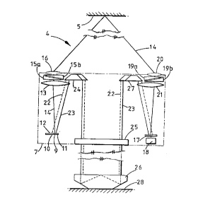
i~ ~hown in ~igure 4 a part o~ a bridge 28, ca~ried on
gro~nd-~ounted supports 30,31, the ~ta~lity o~ which is to
~e measured. The ~y~o~s are equipped ~ith reflectors
32,33 which are monitored remotely ~y a diqplacement
~easurement apparatus 34 shown mounted on a tripod 35. The
tripod may be mounted anywhere and need not be ~table Co a
high order of acc~racy ~ince any ~..ov~".e~t ~hereof will
affect equally ~he measurementc made from the re~lector~
32,33 and will not influence the calculation of their
relative ,..~ nt. Th~ apparatu~ 34 fo~ms ~he datum for
the ~ystem ~n a manner 8;m~l ~ to the hou~ing 7 of
~igurc 2.
Figure 5 ~hows in mare detail the optical c~...~.,ent~
whic~ e the di~placement ~ca~ure~ent apparatus 34 o~
Figure 4 (again the diagram i~ cG."y~es3ed in the
lon~it~ n~l direction for clarlty). The active ~ L,~ ~nt~
o~ the sy~tem are con~ained inside a protective ~ou~ing 36
~itted with ~uita~le window.~ 37, 3R, ~ha~e accive
CA 02213501 1997-08-20
Wo ~U2C410 1 ~ , 7
~9
~ o~ ~ ~nts are in turn rigidly ~ecured within the ~ousing
36 to ~ensibly ~nir; ~e errors arising ~rom vibration and
relative l.~ov~.l.ent.
The hou~ing 36 contain~ an illuminated ~ource ob]ect
39 in the ~ocal pl~ne o~ a collimating lens 40. A region
o~ the ~ource o~ject cont~;nin~ a ~ir~t identifia~le
markin~ 41 i~ projected by the col}imating len~ 40 and
directed by a pair o~ adjustable steering wedges 42a,4~b so
as to he inciden~ on the plane mirror 32 mounted on the
first remotc bridge support 3~. The beam is reflected by
the bridge mounted mirror 32 and ~eturn~ towards t~e
di~placement mea~urement apparatus hou~ing 34. The
reflec~ed beam pa~ses 'chrough a receiv~ng pair of steering
wedges 43a,43b, and a l~n~ ~ ~hlch ~ocu~e~ ~h~ bea~ to
give a sharp image o~ t~e mark 41 on the Yen~itive
detec~ion ~urface o~ a TV camera 45.
A second region of the7~0urce object 39 con~a~n;n~ a
~econd identifia~le marking 46 i~ ~;mil~rly directed to the
second plane mirror 33 mounted on the ~econd remote bridse
support 31 by means of the -~ame collimating len~ 40 and a
se~ond pair of steering wedges 47a,~7b~ A second receiving
pair o~ s~eerLng wedge~ 4~a,48b and the ~ame receiving lens
44 ~orm a ~harp image o~ t~e second mark 46 on the ~V
camera 45. An e~aluation means 49 is connected to the TV
camera output.
It will be appreciated from ~igures 4 and 5, that any
displacement o~ either mirror 32,33 will cause the image of
the ~orresponfl~"~ source o~ect mark 41,46 facused onto the
TV camera 45 ~o move acros~ the camera surface and, if the
disRlac~m~nt of the mirror is great eno~sh, to move o~f the
~ur~ace o~ ths camera. The nature of the identifiabl~
marks ~1,4~ iB chosen so that they can be individ~al~y
located in the output TV ima~e by a readily available
automatic cla-~sification and tracking ~;yBtem connected to
the video outpu~, ~or example one mark could be a circle
and ~he other mark could be ~ cros~ The output from such
a tracki~g system, ~hich forms part o~ the evaluation means
CA 02213501 1997-08-20
wo ~6n64l0 rcrt~ss~37s
49 ha~ing a E~rora~e unit and an arithn~etic unit, i8 an
~x,y) po~ition co-ordina~e fo~ each. of the marks. sy
subtracting the po~itions of the ~irst and ~econd mark
images, the relative motion o~ the two mirrors 32, 33 and
their re~pective bridge supports 30,31 can ~e deduced. ~e
measu ~ ~ ~ensitivity o~ the two ~h~nn~l~ ca~ ~e
e~tabli~hed _y te-..~oLdrily inBerting a wed~e of known
de~iation into each ~h~nnol and r~ording the correspo~;n~
image co-ordinate ~hanges. Only the se~s of steering
wedges 42a,42_,47~,47b,43b,48a,48b are not co~on to ~oth
ch.~n"ols, but these ~o *~ nt~ can be su~cessfully mounted
with a high degree o~ ~tability. All ocher in~tabilities
affect both ch~mPl~3 e~ually and are thus ~,G..,ye--sated for
whe~ the rel~ti~ mo~ ...2r.t o~ the two ~irrors i~ ~inally
obt~ln~ ~y subtraction. The second measurement ch~nn~ in
this ~mhs~mont is per~orming the ~ame function as the
first reference rh~nnel of the e~ m~nt in Figure 2.