Note: Descriptions are shown in the official language in which they were submitted.
CA 02213522 2008-06-05
- 1 -
CATHETER FOR DETACHING ABNORMAL DEPOSITS IN HUMAN
BLOOD VESSELS
The invention relates to a catheter of the
type known as a rotary catheter. Rotary catheters for
detaching abnormal deposits from blood vessels in
humans generally consist of a cutting tool which is
arranged at its front end and which has a stator and a
rotor which can be set in rotation by means of a rotary
drive mechanism of a drive unit. The rotor is equipped
with a cutting edge within the circumferential surface,
and also with a tubular sheath for discharging the
deposits which have been detached.
A catheter of this kind is used in particular
for treating occlusive diseases of the arteries by
dislodging and breaking up stenoses and blood clots.
It is introduced into the artery or vein and is
advanced as far as the stenosed area which is to be
treated. A cutting tool which can be driven in
rotation is arranged at its front or leading end.
In the case of a catheter known from WO-Al-
91/01114, and along the lines of that described above,
the rotor arranged inside the stator has, on its end
face directed counter to the direction of advance of
the catheter, a circumferentially extending, undulating
cutting edge. Within its circumferential surface, the
stator has a cutout with a"beak-like" margin directed
counter to the cutting edge of the rotor. If, during
its advance on the side of the cutout in the stator,
the catheter hits upon deposits, then these deposits
pass at least partially into the cutout. The advance
of the catheter must then be interrupted and the
cutting tool must be pre-tensioned against the deposits
by means of a manually operated tensioning device
engaging on the opposite side of the artery or vein.
The rotor which is driven in rotation must then be
drawn back by hand against the margin in the stator
CA 02213522 2006-03-08
- 2 -
cutout, by means of an operating device engaging on its
flexible drive shaft, while its cutting edge cuts off
the deposits protruding into the cutout, the margin in
the stator acting as a counterstay. The cutting
procedure accordingly takes place in the longitudinal
direction with respect to the catheter. The deposits
which have been cut off are sucked off by means of a
vacuum applied to the catheter tube.
This known catheter is complicated to operate
and does not permit a continuous advance. It is
additionally associated with the risk that it will
pinch the deposits via its "beak-shaped" edge if it is
advanced too far. In these circumstances, injury to
the artery or vein cannot be ruled out.
A further known catheter, the one from EP-Bl-
0,267,539, has as its cutting tool a substantially
elliptical milling cutter which is provided with
abrasive material on its surface and is driven at a
speed of up to 160,000 rpm. The milling cutter is
connected via a flexible drive shaft to a rotary drive
mechanism which is arranged at the other end of the
catheter. The drive shaft runs through a tubular
sheath which serves as a catheter tube. A guide wire
extending right through the drive shaft is introduced
into the artery or vein before introduction of the
catheter and is pushed forwards.
In this known rotary catheter, it is not
possible to exclude the risk of the vessel wall being
damaged, particularly at a curve, and in some cases
even being drilled through.
Another known rotary catheter has a cutting
tool which has two stripping blades and which is driven
at a speed of 750 rpm. In this catheter, there is a
risk that the stripping blades may, particularly at the
relatively slow circumferential speed, pinch or tear or
get caught in the vessel wall.
CA 02213522 2006-03-08
- 3 -
The invention is therefore based on the
object of providing a catheter which is of the type
mentioned at the outset and which on the one hand
ensures that abnormal deposits in the blood vessels of
humans are dislodged cleanly, and on the other hand
makes damage to the vessel wall highly improbable.
According to the invention, the object set is
accomplished by means of a catheter for detaching
abnormal deposits from blood vessels in humans, with a
cutting tool which is arranged at its front end and
which has a stator and a rotor which can be set in
rotation by means of a rotary drive mechanism of a
drive unit. The rotor is equipped with a cutting edge
within the circumferential surface, and also with a
tubular sheath for discharging the deposits which have
been detached. Also, the rotor surrounds a portion of
the stator as external rotor, and the at least one
opposing cutting edge is arranged in the
circumferential surface of the stator portion and
interacts in a shearing acting with the cutting edge of
the rotor.
The catheter according to the invention
ensures that only deposits which are protruding and
which come between the cutting edges can be caught and
dislodged. The possibility of the vessel wall being
damaged by the cutting tool is virtually ruled out
here. Moreover, the risk of the cutting tool of such a
catheter tearing and pinching the vessel wall is in
practice eliminated by the shearing action in
conjunction with the opposite cutting edge.
In a preferred embodiment in which the rotor
and the portion of the stator are cylindrical, at least
in the area of the cutting edges, the rotor attacks the
deposits radially. This ensures that it is not
possible, for example in the area of curves, to drill
straight into the vessel wall.
CA 02213522 2006-03-08
- 4 -
Additional safety against damage to the
vessel wall is afforded by an embodiment in which
shearing slots are arranged in the circumferential
surfaces of the stator portion and of the rotor, their
margins being designed as the cutting edges. By means
of the provision of shearing slots, in the final
analysis only those deposits which protrude into the
shearing slots are detached.
In an embodiment in which the stator portion
and the rotor have two shearing slots each, which are
offset by 180 to each other in the circumferential
direction, symmetry of the shearing action results
since diametrically opposite sites on the vessel wall
are attacked simultaneously. This results in a better
concentric running of the rotor than would be possible
if the latter were to attack the vessel wall only at
one circumferential site.
A swivel drive mechanism can be connected to
the protruding rear end of the tubular sheath or, in a
miniaturized configuration, can act directly on the
stator. It is also possible to arrange a miniaturized
reduction gear unit between the rotor and the stator in
order to drive the stator by means of the rotational
movement of the rotor, preferably in the opposite
rotational direction in relation to the rotor.
A preferred embodiment is to arrange the at
least one cutting edge of the stator to run in an
undulating configuration in at least approximately the
axial direction, relative to a cylindrical surface. It
is also possible, however, to arrange straight cutting
edges inclined with respect to the axial direction, or
to use cutting edges which are knife edges.
An embodiment in which the rotor is at least
partially tapered in the direction of its front end
allows the rotor, even before the shearing action is
started, to dislodge from the vessel wall any deposits
which are protruding or bulging into the shearing slot.
CA 02213522 2006-03-08
- 5 -
The following embodiment ensures that the
rotor forces its way through the blood vessel, in
particular at stenosed or blocked sites: that the rotor
has one front face and two adjoining bevelled surfaces
lying opposite each other, and the front face has on
the circumference, forwardly extending projections.
It is preferred that the stator and rotor are
of metal. It is also possible, however, to use other
materials for this purpose, for example suitable
plastics.
It is preferred that the stator be attached
in a manner fixed in terms of rotation and tensioning,
to the tubular sheath serving as catheter tube. It is
also possible, however, to fasten the stator in a
movable manner at the tip or the leading end of the
tubular sheath.
It is preferred that the stator be mounted
such that it revolves or can swivel to and from about
its longitudinal axis. This ensures that the cutting
tools dislodges material about the whole circumference
of the vessel wall, the stator being moved in such a
way that the shearing slots arranged in it execute
either a slowly revolving or reversible swivel movement
about the longitudinal axis of the stator. With such a
movement, the stator executes either a continuously
helical movement, or a helical movement directed
alternately to the left and to the right, during the
advance. In the most straightforward case, such a
movement can be effected manually by the attending
physician if the stator is connected to the tubular
sheath in a manner fixed in terms of rotation and
tensioning.
It is preferred that the stator is sleeve-
like formed and has in its circumferential surface, at
its end adjacent to the tubular sheath, at least one
hole for anchoring the sheath, which is made of plastic
and is press-fitted into the stator, in a manner fixed
CA 02213522 2006-03-08
- 6 -
in terms of rotation and tensioning. This provides a
particularly simple way of fastening the stator on the
tubular sheath so that they are fixed in terms of
rotation and tensioning.
It is preferred that the rotor be driven by
connecting the rotor to the front end of a flexible
drive shaft mounted in the tubular sheath, the rear end
of which drive shaft can be connected to the rotary
drive mechanism. It is also possible, however, to
drive the rotor directly by means of a miniaturized
gearing.
It is preferred that the flexible drive shaft
is designed as a conveyor worm or conveyor screw and is
wound helically in such a way that, in the driven
state, it conveys the broken-up deposits in the
direction of the drive unit. This permits immediate
withdrawal of the deposits which have been detached and
broken up, so as to avoid these deposits remaining in
the bloodstream.
The efficacy of the conveyor screw is
improved by an embodiment in which a guide wire extends
coaxially through the flexible drive shaft designed as
conveyor worm or conveyor screw.
An illustrative embodiment of the invention
is explained in greater detail with reference to the
drawings, in which:
Figure 1 shows a rotary catheter in a general
view, with drive mechanism, guide wire and collection
container for the deposit fragments which have been
detached,
Figure 2 shows an elevation of the head part
of the rotary catheter according to Figure 1, but on a
larger scale,
Figure 3 shows the head part as in Figure 2,
but in a plan view,
CA 02213522 2006-03-08
- 7 -
Figure 4 shows an end view of the rotor and
the guide wire of the rotary catheter according to
Figure 3,
Figure 5 shows the head part in cross-section
along the cutting line V-V in Figure 3,
Figure 6 shows the rotary catheter according
to Figure 3, but with the rotor turned through 90
relative to the stator,
Figure 7 shows a longitudinal section through
the head part of the rotary catheter according to
Figure 2,
Figure 8 shows guide wire and helical
winding, in a cross-section through the helical
winding,
Figure 9 shows the head part of the catheter
according to Figure 1 in a perspective representation,
viewed from the front end, and
Figure 10 shows the head part of the catheter
according to Figure 1 in a perspective representation,
as seen from the drive side.
The catheter 12 shown in Figure 1 has, at its
front end 12a, a cutting tool which consists of a
stator 14 and rotor 16. At its rear end 12b, the
catheter 12 is connected to a rotary drive mechanism
20a of a drive unit 20 via a discharge chamber 18. A
flexible drive shaft is mounted in a tubular sheath 22
serving as catheter tube and connects the rotor 16 to
the rotary drive mechanism 20a. A guide wire 24 runs
through the entire length of the catheter 12, and its
front end 24a protrudes from the rotor 16 and its rear
end 24b from the drive unit 20. A collection container
28 is linked to the discharge chamber 18 in the radial
direction via a tube or a pipe 26.
The tubular sheath 22 is connected to a
swivel drive mechanism 20b in a manner fixed in terms
of rotation. This mechanism can be provided either for
a revolving swivel movement or for a reversible swivel
CA 02213522 2006-03-08
- 8 -
movement. Its speed lies substantially below that of
the rotary drive mechanism 20a.
The swivel drive mechanism 20b can also be
omitted if only the tubular sheath 22 is mounted in a
rotatable manner. In such a configuration, the tubular
sheath can be set by hand into a revolving or
reversible swivel movement when the catheter 12, on
being advanced, has reached the site which is to be
treated.
It is also possible to uncouple the stator 14
from the tubular sheath 22 and for the stator 14 alone
to be mounted so as to swivel, and to equip the stator
directly with a miniaturized swivel drive mechanism
(not shown).
When using the catheter 12, the guide wire 24
is introduced, with its front end 24a leading, into the
artery or vein which is to be treated, and it is
advanced as far as the stenosed area and then
manoeuvred through the latter, with radiographic
monitoring. The catheter 12 is then passed along the
guide wire 24. As soon as the rotor 16 has reached the
area which is to be treated, the rotary drive mechanism
20a at least is switched on in order to detach the
undesired deposits by means of the cutting tool. The
speed of rotation of the rotor 16 preferably lies in
the range of between 30,000 and 40,000 rpm. The
catheter 12 is advanced slowly as the operation
proceeds and in so doing is set in a slow swivel
movement either by means of the swivel drive mechanism
20b or by hand. The deposits which have been dislodged
and broken up are carried off through the tubular
sheath 22 as far as the discharge chamber 18 and they
pass from there into the collection container 28.
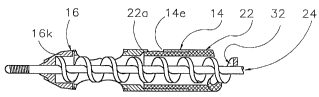
Figure 2 shows the front end 12a of the
catheter 12 with its stator 14, its rotor 16 designed
as external rotor, its tubular sheath 22, and the front
end 24a of the guide wire 24. The tubular sheath 22 is
CA 02213522 2006-03-08
- 9 -
shown cut away at 30 to reveal the flexible drive shaft
32 which, inside the rotor 16, is fixed to the latter
in terms of rotation. The guide wire 24 extends through
the inside of the drive shaft 32. The drive shaft 32 is
additionally designed as a conveyor worm or conveyor
screw in order to convey the deposits, which have been
dislodged by the cutting tool 14, 16, through the
tubular sheath 22 to the discharge chamber 18.
A portion 14a of the stator 14 extends into
the rotor 16. It will be seen that the stator portion
14a and the rotor 16 engage one within the other like a
bushing. The stator portion 14a has two shearing slots
14b, 14c which are offset 180 to each other about the
circumference. The rotor 16 likewise has two slots
16b, 16c which are offset 180 to each other about the
circumference.
From Figure 3 it will be seen that the
shearing slot 14b of the stator portion 14a is narrower
than that 16b of the rotor 16 in the circumferential
direction. One margin of the rotor slot 16b is designed
as cutting edge 16d. The margin of the stator slot
14b, facing in the opposite direction, is designed as
cutting edge 14d. This cutting edge 14d extends in an
at least approximately undulating configuration.
The cutting edge 16d and the cutting edge 14d
interact in a shearing action. Cutting edges of this
type are in each case arranged in both slots 14b, 14c;
16b, 16c which are also referred to as shearing slots,
in other words arranged 180 in relation to one another
in the circumferential direction. The front end 16a of
the rotor 16 tapers at least approximately conically.
In this way, the stenosed area of the artery or vein to
be treated is widened upon insertion of the catheter
12.
Figure 4 shows the front elevation of the
rotor 16 and of the front end 24a of the guide wire 24.
Also shown are two bevelled surfaces 16e, l6f of the
CA 02213522 2006-03-08
- 10 -
rotor 16, which surfaces run in opposite directions and
between which there is a front face 16g. The front
face 16g has, on the circumference, horn-like,
forwardly extending projections 16h, 16i (Figure 3).
The front of the rotor 16 serves in particular to break
up clots obstructing the passage, in order to force a
path for the catheter 12 along the blood vessel.
Figure 5 shows a cross-section along V-V in
Figure 3. The rotor 16 is driven in the direction of
the arrow 34. The cutting edges 16d of the rotor 16 in
this case attack via the circumference the deposits,
for example the stenoses, and break these up. The
cutting edges 14d of the stator portion 14a achieve a
shearing action in conjunction with the cutting edges
16d of the rotor, with the sheared-off fragments of the
deposits passing into the region of the drive shaft 32
and conveyor screw and being conveyed onwards from
there as far as the discharge chamber 18 (Figure 1).
In this representation it should be noted that the
external diameter of the rotor 16 is less than 3 mm..
The rotor 16 and the stator 14 are preferably
made of metal. The guide wire 24 is a steel wire with
nib tip 24c. The drive shaft 32 also serving as
conveyor worm or conveyor screw consists of a coated
steel wire, for example. The tubular sheath 22 is
preferably made of plastic.
For connecting the stator 14 to the tubular
sheath 22 in a rotationally fixed manner, the front end
22a of the latter (Figures 2 and 3) is press-fitted
into the stator 14, for example. For securing
purposes, holes 14e are arranged in the circumferential
surface of the stator 14, and the pressed-in tube
material 22b swells slightly into said holes 14e.
In the view according to Figure 6, the
position of the stator 14 corresponds to that in Figure
3, and the position of the rotor 16 corresponds to that
in Figure 2. The slight difference in diameter between
CA 02213522 2006-03-08
- 11 -
the stator portion 14a and the rotor 16 is clearly
visible here.
From the longitudinal section according to
Figure 7, it can be seen in particular that the drive
shaft 32 extends with its front end 32a into the head
part 16k of the rotor 16 and is there connected to the
latter in a manner fixed in terms of rotation, for
example press-fitted into it. It can also be seen how
the tubular sheath 22 is secured in the stator 14 via
the holes 14e, in a manner fixed in terms of rotation
and tensioning.
Figure 8 shows in particular the rectangular
cross-section of the wire 32c of the helical drive
shaft 32 which at the same time also serves as conveyor
worm or conveyor screw. The arrangement of the guide
wire 24 coaxially inside the drive shaft 32 results in
a particularly high degree of efficacy as conveyor worm
or conveyor screw. The dislodged fragments of the
deposits are conveyed in a virtually linear manner
inside the tubular sheath 22.
Figures 9 and 10 show all the parts already
described, but in a perspective representation.