Note: Descriptions are shown in the official language in which they were submitted.
CA 02213681 1997-10-09
BACKGROI~ND OF THE INVENTION
Field of the Invention
The present invention relates to an adjustable bed canopy and curtain
system and more particularly pertains to providing a system that has a plurality
of tubular members coupled together and coupled to vertical posts for forming
a frame that can be positioned around any bed of any size and further includes
a sheet draped over the frame to transform the bed into a canopy bed.
Description of the Prior Art
The use of a canopy is known in the prior art. More specifically,
canopies heretofore devised and utilized for the purpose of enclosing a bed are
known to consist basically of familiar, expected, and obvious structural
configurations, notwithstanding the myriad of designs encompassed by the
crowded prior art which has been developed for the fillfillm~nt of countless
objectives and requirements.
CA 02213681 1997-10-09
By way of example, United States Patent Number 5,241,717 to Ward et
al. Discloses protective structure and bed frame with rigid canopy. United
States Patent Number 4,965,895 to Shustov discloses a earthquake shelter with
bed support and canopy. United States Patent Number 4,945,586 to Cross,
Markowitz and Selgrath discloses a canopy bed frame assembly. United States
Patent Des. 299,193 to Brandis, Jr. discloses a canopy for a bed. United States
Patent Des. 283,179 to Scully and Waxman disclosed a canopy bed. Lastly,
United States Patent Number 4,068,333 to Gutner discloses a canopy frame for
bed.
While these devices fulfill their respective, particular objectives and
requirements, the aforementioned patents do not describe an adjustable bed
canopy and curtain system that provides a system that will turn any bed turned
into a canopy bed by using a frame formed from interlocking tubular members
and vertical post with the frame covered by a sheet of fabric.
In this respect, the adjustable bed canopy and curtain system according
to the present invention substantially departs from the conventional concepts
and designs of the prior art, and
CA 02213681 1997-10-09
in doing so provides an apparatus primarily developed for the purpose of
a system that has a plurality of tubular members coupled together and coupled
to vertical posts for forming a frame that can be positioned around any bed of
any size and further includes a sheet draped over the frame to transform the bed
into a canopy bed.
Therefore, it can be appreciated that there exists a continuing need for a
new and improved adjustable bed canopy and curtain system which can be used
to provide a system that has a plurality of tubular members coupled together
and coupled to vertical posts for forming a frame that can be positioned around
any bed of any size and further includes a sheet draped over the frame to
transform the bed into a canopy bed. In this regard, the present invention
substantially fulfills this need.
CA 02213681 1997-10-09
SUMMARY OF THE INVENTION
In view of the foregoing disadvantages inherent in the known types of
canopies now present in the prior art, the present invention provides an
improved adjustable bed canopy and curtain system. As such, the general
purpose of the present invention, which will be described subsequently in
greater detail, is to provide a new and improved adjustable bed canopy and
curtain system and method which has all the advantages of prior art and none
of the disadvantages.
To attain this, the present invention essentially comprises a generally
rectangular sheet of fabric. The sheet of fabric has a top portion with a pair of
short side portions and a pair of long side portions extl~n~ing from the sheet.
One of each of the short side portions is contiguous with each of the pair of
long side portions. Each short side portion has a slit therein and each long side
portion has a slit therein, and forms corner panels. Included are at least four
vertical post. Each has an upper end and a lower end with a foot portion. Each
vertical post has a locking protrusion that projects form the post. The locking
protrusion of each vertical post has a leaf spring
CA 02213681 1997-10-09
fixedly attached to an interior surface of the vertical post. The leaf
spring, of each vertical post, allow the locking procrusion to be pressed
from the projected position into a position flush with an exterior surface
of the respective vertical post.
Also, a frame member has a first pair of "L" shaped tubular
members and a second pair of "L" shaped tubular members. Each of
the first pair of "L" shaped tubular members have a lower elongated
portion with a bottom edge. Each of the first pair of "L" shaped tubular
members have an upper elongated portion with a top edge. The lower
elongated portions and the upper elongated portions of the first pair of
tubular member have a uniform diameter. Each of the second pair of
"L" shaped tubular members has a lower elongated portion with a
bottom edge, each of the second pair of "L" shaped tubular members
having an upper elongated portions with a top edge. The lower
elongated portions of the second pair of tubular members having a
diameter. The upper elongated portions of the second pair of tubular
members having a diameter less thank the diameter of the lower
elongated portions of the second tubular member.
CA 02213681 1997-10-09
One of the first pair of "L" shaped tubular members has a
horizontal bar projecting outwardly. Another of the first pair of "L"
shaped tubular members has a horizontal bar projecting outwardly, and
sized for positioning within the horizontal bar of the one first palr of
tubular members. One of the second pair of "L" shaped tubular
members has a horizontal bar projecting outwardly. Another of the
second pair of "L" shaped tubular members has a horizontal bar
projecting outwardly, and sized for positioning within the horizontal bar
of the one second pair of tubular members. The diameter of each of the
upper elongated portions of each first pair of tubular members is sized
for receiving one of the upper elongated portions of the second pair of
tubular members to allowing coupling between the first tubular member
and the second tubular member. Each of the lower elongated portions of
each of the first tubular members and each of the lower elongated
portions of each of the first tubular members and each of the lower
elongated portions of each of the second tubular member are positioned
over one of the four vertical post. This placement occurs when the first
and second tubular members are coupled.
Lastly, the top portion of the rectslngulSIr sheet of fabric is
positioned over the coupled first and second pair of
CA 02213681 1997-10-09
tubular members. The corner panels of the sheet of fabric are gathered
when adjacent the lower elongated portions of the coupled first and
second pair of tubular members and form a plurality of canopy corner
panels. The plurality of canopy corner panels cover the lower elongated
portions of the coupled first and second pair of tubular members when
the lower elongated portions are positioned over the four vertical post.
The frame with the sheet of fabric is positioned over and around a bed.
There has thus been outlined, rather broadly, the more important
features of the invention in order that the detailed description thereof that
follows may be better understood and in order that the present
contribution to the art may be better appreciated. There are, of course,
additional features of the invention that will be described hereinafter and
which will form the subject matter of the claims appended hereto.
In this respect, before explaining at least one embodiment of the
invention in detail, is to be understood that he invention is not limited in
its application to the details of construction and to the arrangements of
the components set forth in the following description or illustrated in the
CA 02213681 1997-10-09
drawings. The invention is capable of other embodiments and of being
practiced and carried out in various ways. Also, it is to be understood that the
phraseology and terminology employed herein are for the purpose of
descriptions and should not be regarded as limiting.
As such, those skilled in the art will appreciate that the conception, upon
which this disclosure is based, may readily be utilized as a basis for the
designing of other structures, methods and systems for carrying out the several
purposes of the present invention. It is important, therefore, that the claims be
regarded as including such equivalent constructions insofar as they do not
depart from the spirit and scope of the present invention.
It is therefore an object of the present invention to provide a new and
improved adjustable bed canopy and curtain system which has all of the
advantages of the prior art canopies and none of the disadvantages.
It is another object of the present invention to provide a new and
improved adjustable bed canopy and curtain.
CA 02213681 1997-10-09
system which may be easily and efficiently manufactured and marketed.
It is further object of the present invention to provide a new and
improved adjustable bed canopy and curtain system which is of durable and
reliable constructions.
An even further object of the present invention is to provide a new and
improved adjustable bed canopy and curtain system which is susceptible of a
low cost of manufacture with regard to both materials and labor, and which
accordingly is then susceptible of low prices of sale to the consuming public,
thereby making such adjustable bed canopy and curtain system economically
available to the buying public.
Even still another object of the present invention is to provide an
adjustable bed canopy and curtain system for providing a system that has a
plurality of tubular members coupled together and coupled to vertical posts for
forming a frame that can be positioned around any bed of any size and further
includes a sheet draped over the frame to transform the bed into a canopy bed.
CA 02213681 1997-10-09
Lastly, it is an object of the present invention to provide a new and improved
adjustable bed canopy and curtain system. The system includes a sheet of
fabric, at least four vertical post and a frame member. The frame member has
a first pair of "L" shaped tubular members and a second pair of "L" shaped
tubular members. Each of the first and second pair of "L" shaped tubular
members have a lower elongated portion and an upper elongated portion. Each
of the first and second pair of "L" shaped tubular members have a horizontal
bar projecting from one of the lower elongated portions and capable of coupling
with a horizontal bar of another of the lower elongated portions. The upper
elongated portion, of each of the first pair of tubular members, receives the
upper elongated portion of each of the second pair of tubular members when
the horizontal bars of each tubular member are coupled. Each of the lower
elongated portions, of each of the first and second tubular members, are
positioned over one of the four vertical post when the first and second pair of
tubular members are coupled. The sheet of fabric is positioned over the
coupled first and second tubular members.
These together with other objects of the invention, along with the various
features of novelty which characterize the
CA 02213681 1997-10-09
invention, are pointed out with particularity in the claims annexed to and
forming a part of this disclosure. For a better understanding of the invention,
its operating advantages and the specific objects attained by its uses, references
should be had to the accompanying drawings and descriptive matter in which
there is illustrated preferred embodiments of the invention.
CA 02213681 1997-10-09
B~F DESCRITPION OF THE DRAWINGS
The invention will be better understood and objects other than those set
forth above will become apparent when consideration is given to the following
detailed description thereof. Such description makes reference to the annexed
drawings wherein:
Figure I is a prespective view of the preferred embodiment of the
adjustable bed canopy and curtain system constructed in accordance with the
principles of the present invention.
Figure 2 is a side view of the present invention of Figure I .
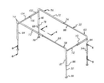
Figure 3 is an isometric view of the frame of the present invention.
Figure 4 is a cut-away view of the present invention taken along line 4-4
of Figure 3.
14
CA 02213681 1997-10-09
Figure 5 is a cut-away cross-sectional view of the present invention
taken along line 5-5 of Figure 3.
Figure 6 is a cross-sectional view of the foot of the vertical post of the
present invention taken along line 6-6 of Figure 3.
The same reference numerals refer to the same parts through the various
Figures.
CA 02213681 1997-10-09
DESCRIPTION OF THE PREFFERRED EMlBODIMENT
With reference now to the drawings, and in particular to Figure 1
thereof, the preferred embodiment of the new and improved Adjustable bed
canopy and curtain system embodying the principles and concepts of the
present invention and generally designated by the reference numeral 10 will be
described.
The present invention, the Adjustable bed canopy and curtain system 10
is comprised of a plurality of components. Such components in their broadest
context include a frame and a sheet of fabric. Such components are
individually configured and correlated with respect to each other so as to attain
the desired objective.
Specifically, the present invention includes a generally rectangular sheet
of fabric 14. The sheet has a top portion 16 with a pair of short side portions
18 and a pair of long side portions 20. The short side portions and the long
side portions, as seen in Figure I, extend from the top portion. One of each
short side portion is contiguous with each of the pair of long side portions.
Each short side portion has a slit 22. Each
16
CA 02213681 1997-10-09
long side portion has a slit 24. Slits in the pair of short side portions and the
pair of long side portions allow for the formation of corner panels 26.
As best illustrated in figure 3, at least four vertical post 32 are included.
Each vertical post has an upper end 34 and a lower end 36 with a foot portion
38. Each vertical post, as seen in Figure 5, has a locking protrusion 42. The
locking protrusion of each vertical post projects outwardly from the vertical
post. The locking protrusion of each vertical post has a leaf spring 44 that is
fixedly attached to an interior surface 46 of the vertical post. The leaf spring of
each vertical post will allow the locking protrusion to be pressed and removed
from the projected position to a position flush with an exterior surface 48 of the
respective vertical post.
Also, a frame member 50 is provided. The frame member has a first
pair of "L" shaped tubular members 54 and 56, and a second par of "L" shaped
tabular members 58 and 60. Each of the first pair of "L" shaped tubular
members have a lower elongated portion 64 and 66 with a bottom edge 68.
Each of the first pair of "L" shaped tubular members have an upper elongated
portion 72
CA 02213681 1997-10-09
with a top edge 74. The lower elongated portion and the upper elongated
portion of the first pair of tubular members have a uniform diameter. The
lower elongated portion and the upper elongated portion of the first pair of
tubular members each have a plurality of apertures 78. The apertures of the
lower elongated portions of the first pair of tubular members are
proportionately spaced from the bottom edge 68. The apertures of the upper
elongated portions of the first pair of tubular members are proportionately
spaced from the top edge 74.
Additionally, each of the second pair of "L" shaped tubular members
have a lower elongated portion 82 and 84 with a bottom edge 86. Each of the
second pair of "L" shaped tubular members have an upper elongated portion 88
with a top edge 92. The lower elongated portions of the second pair of tubular
members have a diameter. The upper elongated portions of the first pair of
tubular members have a diameter less than the diameter of the lower elongated
portions of the second pair of tubular members.
The lower elongated portions and the upper elongated portions of the
second pair of tubular members each have a
CA 02213681 1997-10-09
plurality of apertures 94. The apertures of the lower elongated portions of the
second pair of tubular members are proportionately spaced from that bottom
edge 86. The apertures of the upper elongated portions of the second pair of
tubular members are proportionately spaced from the top edge 92. Each of the
upper elongated portions of the second pair of tubular members have a locking
protrusion 98, as seen in Figure 4. The locking protrusion 98 of the upper
elongated portions of the second pair of tubular members function identical to
the locking protrusion 42 of Figure 5 and described above.
It can be seen in Figure 3 that one of the first pair of "L" shaped tubular
members 56 has a horizontal bar 102 projecting outwardly. Another ofthe first
pair of "L" shaped tubular members 54 has a horizontal bar 104 projecting
outwardly. The horizontal bar of the other of the pair of "L" shaped tubular
members is sized to portioned within the horizontal bar 102 of the one first pair
of tubular members 56. The two horizontal bars are locked in position with a
locking protrusion 106 like the one depicted in Figure 5. One of the second
pair of "L" shaped tubular members 60 has a horizontal 110 bar projecting
outwardly. Another of the second pair of "L" shaped tubular
19
CA 02213681 1997-10-09
members 59 has a horizontal bar 112 projecting outwardly. The horizontal bar
1 12 is sized to be positioned and locked within the horizontal bar 1 10 of the one
second pair of tubular members 60.
Furthermore, The diameter of each of the upper elongated portions 88 of
each first pair tubular members is sized to received one of the upper elongated
portions of the second tubular members and couples of the first tubular member
and the second tubular member. Each of the lower elongated portions of the
each of the first pair of tubular members and each of the lower elongated
portions of each of the second pair of tubular members are positioned over one
of the four vertical post when the post and second tubular members are
coupled. When the lower elongated portions of the frame are coupled to the
vertical post the foot portions allows the frame to be positioned upright around
a bed 1 18. The foot portions each have a non-slip pad 120 to increase the
stability of the frame by preventing excess movement of the frame.
Lastly, the top portion 16 of the rectangular sheet of fabric is positioned
over the coupled first and second pair of
CA 02213681 1997-10-09
tubular members of the frame 50. The corner panels of the sheet of fabric are
gathered, when adjacent the lower elongated portions of the coupled first and
second pair of tubular members, to form a plurality of canopy corner panels
122. The plurality of canopy corner panels cover the lower elongated portions
of the coupled first and second pair of tubular members. This positioning of
the sheet 14 is done when the lower elongated portions are positioned over the
four vertical post. Finally, the frame with the sheet of fabric over it is placed
around the bed.
The present invention is an adjustable bed canopy and curtain system
that provides a simple and easy way to turn any standard bed into a canopy
bed. The frame of the invention is structured from metal or plastic tubing. The
vertical post that support the frame are constructed of the same material used to
make the frame. The frame used interlocking tubing and allows the height,
length and width of the frame to be adjusted to match the bed size. The tubing
may be made available so as to fit beds ranging to a toddler's bed to a king size
bed. The foot portion of each vertical post is covered with a non-slip material,
preferably rubber. The non-slip material helps to stabilize the
CA 02213681 1997-10-09
frame when it is positioned around the bed and will prevent damage to flooring
or carpeting. The sheet of fabric used with the frame is any material of choice.
Once the fabric is draped over the frame member the corner panels are gathered
and held in place by a tie.
As to the manner of usage and operation of the present invention, the
same should be apparent from the above description. Accordingly, no further
discussion relating to the manner of usage and operation will be provided.
With respect to the above description then, it is to be realized that the
optimum dimensional relationships for the parts of the invention, to included
variations in size, materials, shape, form, ffinction and manner of operation,
assembly and use, are deemed readily apparent and obicous to one skilled in the
art, and all equivalent relationships to those illustrated in the drawings and
described tin the specification are intended to be encompassed by the present
invention.
Therefore, the foregoing is considered as illustrative only of the
principles of the invention. Further, since numerous
CA 02213681 1997-10-09
modifications and changes will readily occur to those skilled in the art, it is not
desired to limit the invention to the exact construction and operation shown and
described, and accordingly, all suitable modifications and equivalents may be
resorted to, falling within the scope of the invention.