Note: Descriptions are shown in the official language in which they were submitted.
CA 02214003 1997-08-27
Y
1
a .
1
.. .,
-,a ~ --.., ..
TflA:v~L,f~TIGt~
Process for the Manufacture of a Std aterial
The invention relates to a process for the manutacture of a strip material in
which
tin at least one side of a support a plastics layer is formed from a mixture
of plastics
material and particulate soluble corpuscles, the soluble corpuscles being
teachable
- S by a solvent to which the plastics material is stable anti that thereafter
the soluble
corpuscles are at least in part leached out of the plastics layer with the
formation of
throughtlow passages.
A strip material of the aforesaid type for employment in a paper machine is
described in EP-B-0 196 045. It comprises a support in the form of a liquid
pervious fabric onto which a layer, 1,3 to S mm thick, of an elastomeric
polymer
resin has been applied. The plastics layer comprises throughflow passages
which
pass from the otherwise smooth and plane outside down to the support and
which,
in the paper machine, serve as de-watering passages.
The production of the throughflow passages is brought about in that textile
fibres
are homogeneously dispersed in the polymer resin, prior to the mixture of
textile
fibres and polymer resin being applied onto the support. As an alternative to
the
aforegoing, a fibre fleece may first be applied onto the support, whereafter
the
coating of polymer resin is applied. In both cases the textile fibres are
composed of
an organic material which can be dissolved by the application of a solvent,
the
CA 02214003 1997-08-27
r
2
plastics layer being resistant to this solvent. The leaching out of the
textile fibres is
carried out after the application of the polymer resin by the application of
the
solvent such that the throughflow passages are formed the configuration and
orientation of which corresponds to the leached out textile fibres.
In a less preferred embodiment particulate corpuscles are proposed instead of
the
textile fibres which are distributed homogeneously in the polymer resin.
Inorganic
salts or their hydrates or oxides are proposed as the material for those
corpuscles.
By appropriate solvents they can be leached out of the polymer resin in the
same
manner as the textile fibres and in the course thereof leave behind pore
cavities.
In the manufacture of the above described paper machine belt difficulties are
experienced with the uniform distribution of the soluble components - either
fibres
or particulate corpuscles - in the polymer resin and with the maintenance of
this
distribution when applying the mixture. The reason is that during the
processing of
the mixture of polymer resin and soluble components demixing takes place so
that
15 there can be no certainty that throughtlow passages are formed by the
leaching out
of the particles. For that reason it is also not possible to produce
distributions of the
soluble components which vary over the cross-section.
Apart from that polymer resins have a tendency after curing to form a closed
surface which inhibits the dissolving out of the soluble textile fibres or
corpuscles
20 contained in the polymer resin. In order to solve this problem, it has been
proposed
in . EP-B-EPO 273 613 to so grind down the surface of the plastics layer, that
a
communication is formed to the soluble fibres and in addition a smooth surface
is
generated. Such a grinding procedure, however, is very time consuming.
Moreover, it is first necessary to apply an appropriate excess of plastics
material
25 and during the grinding procedure dust is formed which must be sucked off
and be
either disposed of or be processed for reuse. Moreover, a smooth surface is
formed
which inhibits a release of the paper strip from the paper machine belt. The
reason
' is that paper strips are inclined to become firmly drawn against smooth
surfaces.
CA 02214003 1997-08-27
3
Apart from the aforegoing disadvantages, paper machine belts of this genus are
claimed to have a number of advantages as compared with known felt materials,
according to_the batt-on-base principle, more particularly an increased
resistance
against permanent deformation and thereby a longer operating life and
resulting
therefrom reduced maintenance costs, improved abrasion resistance and higher
structural strength, lower affinity for contaminating substances as well as
more
uniform pressure distribution and thus improved de-watering characteristics.
The aforedescribed development was preceded by a proposal to embed in the
fibres
of a paper machine felt fibres or particles which can be leached out by means
of a
solvent in relation to which the remaining fibres and the support of the paper
machine belt are solvent resistant, i.e. stable (DE-C-34 19 7 or 8). The
manufacture proceeds such that a non-woven fibre web of insoluble fibres and
soluble components is formed and is needle-bonded onto the support and that
thereafter the paper machine belt is compacted with pressure and heat. In the
25 course thereof the soluble components may melt together. Due to the
resolution of
the soluble components, pore cavities are formed which, in spite of the
previous
compression and the thereby generated high density, provide the paper machine
belt
with the void volume required for de-watering.
It is a disadvantage of this solution that, in spite of the compression, the
durability
is considerably less than with plastics coated supports. Moreover, the
conventional
machines for this purpose, in particular weaving looms and needling machines
cannot be dispensed with.
There has been no lack of attempts to manufacture the paper machine belts
comprising a plastics layer with a support and throughflow passages passing
there
through in a different manner. Thus in EP-B-0 037 387 a strip material is
proposed in which the throughflow passages are produced by perforating a
previously applied plastics foil by means of a laser apparatus. Apart from the
fact
that the throughflow passages do not intercommunicate for which reason a gas
or
water permeation transversely to the plane of the strip material cannot take
place,
CA 02214003 1997-08-27
. - . 4
the manufacture of such strip is moreover exceedingly expensive, in particular
if
major surface areas have to be processed by means of a laser device, as is the
case
with paper machine belts. Moreover, foils of the required , width and having
adequate uniformity cannot be produced.
It is proposed in WO 91/14558 to produce the throughflow passages in that onto
the
non-cured plastics layer a perforated mask is applied which is then radiated.
Due to
this radiation, the plastics material is cured fully in the region of the
perforations of
the mask. After removing the perforated mask the plastics material which then
has
not yet been cured is removed by compressed air. This process as well is
expensive
and leaves behind relatively large tree surface areas and Cor that reason
cannot be
applied universally. Moreover, here as well waste material which has to be
disposed of or recycled is formed.
A different concept was adopted in accordance with the proposal according to
EP-B-0 187 967. In this case, in the context of a paper machine belt, a porous
- 15 plastics layer on a support is created in that loose particles of a
synthetic polymeric
polymer resin of the order of magnitude of 0,15 to 5 mm are distributed on the
surface of a support web and are then subjected to thermal treatment in which
the
polymer resin particles are heated above the softening point whereby they are
fused
together and to the support fabric at their contact localities. Instead or in
combination therewith it is also possible to provide for the application of a
resin-like binder. Instead of the particles, it is also possible to distribute
loose
fibres on the support fabric. After the adhesion of the particles or fibres to
one
another and to the support fabric, cavities remain which render the plastics
layer
liquid pervious.
2 5 Something similar is proposed in accordance with EP-A 0 653 512 except
that in
this case the material strip is initially produced exclusively from polymer
particles
which, by heat action, are inter-bonded at their contact localities. If
required, a
' strengthening structure in the form of a reinforcing may be totally embedded
in the
belt thus formed. This may take the form of a pure fibre product or a fabric.
The
CA 02214003 1999-11-17
particles may also have different diameters in order to generate
a permeability which increases towards the other side.
The disadvantage of strip materials produced according
to this principle resides in that it is very difficult to
5 produce them in a reproducible manner, in particular as regards
permeability. Moreover, their surface is very uneven for which
reason the simultaneous application of pressure and heat -
wherever the particles are formed of fine fibres (EP-B-0 187
967) - or a grinding procedure (EP-A-0 653 512) are proposed for
the purpose of rendering the surface even.
According to WO 95/21285 a polymer coating is applied
by means of a transfer foil with the simultaneous application of
heat and pressure onto a support in which context the polymer
film due to the heat action is transformed on the transfer foil
to coherent droplets with free spaces formed inbetween, as a
result of which the plastics layer applied onto the support is
porous. In this process as well, it is difficult to adjust the
permeability of the plastics layer in a reproducible manner and
to adapt it to whatever requirements are needed. Moreover,
foils of the width required for that purpose are not available
and would also not be producible with adequate uniformity.
The invention is based on the aim to provide a process
for the manufacture of a strip material of the type aforesaid by
means of which a desired distribution of the soluble corpuscles
within the plastics layer can be attained. A further aim
CA 02214003 1999-11-17
5a
resides in so designing the process that the soluble corpuscles
may be leached out of the plastics layer in a simple manner.
This aim is attained according to the invention in
that as the plastics material a plastics powder is prepared
which is mixed with the soluble corpuscles and applied onto the
support and that by heat and pressure treatment from the mixture
of plastics powder and soluble corpuscles a plastics layer with
the soluble corpuscles contained therein is produced before the
soluble corpuscles are at least partly leached out of the
plastics layer.
The invention provides process for the manufacture of
a permeable strip material, in which on at least one side of a
support a plastic layer is produced from a mixture of plastic
material and particulate soluble corpuscles, wherein the soluble
corpuscles are leachable by a solvent to which the plastic
material is stable and that thereafter the soluble corpuscles
are leached out form the plastic layer at least in part, with
the formation of throughflow passages from one side to the other
of the plastic layer sufficient to permit dewatering to occur
characterised in that the plastic material is prepared in the
form of a plastic powder which is mixed with the soluble
corpuscles and applied onto the support and that by heat and
pressure treatment a plastic layer is formed from the mixture of
plastic powder and soluble corpuscles with the soluble
CA 02214003 1999-11-17
5b
corpuscles being contained therein, prior to the soluble
corpuscles at least in part being leached out of the plastic
layer.
CA 02214003 1997-08-27
' 6
By first producing a pulverulent mixture an extraordinarily uniform
distribution of
the soluble particles within the plastics material may be attained. This
distribution
does not change either during or after the application of the powder. The
reason is
that the plastics powder becomes electrostatically charged in such a manner
that the
mixed powder corpuscles of plastics and soluble corpuscles adhere to one
another
and therefore do not change in position. Accordingly, demixing problems do not
arise. The subsequent thermal treatment (sintering) causes a continuous
plastics
layer to be formed from the powder layer. In the course thereof the plastics
powder
is plastified to such an extent that a homogeneous plastics layer is formed,
i.e. a
plastics layer which apart from the soluble corpuscles is substantially non-
porous
and which adheres to the support. This effect is supported by the pressure
treatment
which moreover takes care of a plane exposed surface. This thermal treatment
may
take place in a heating oven or under infrared radiators. The pressure
treatment may
subsequently be carried out in a calender or the like.
The particle size of the corpuscles of the plastics powder and also that of
the soluble
corpuscles as well as their mixing ratio may be adjusted within wide limits
depending on requirements for a desired structure of the plastics layer to
result, in
particular as regards the cavities ~f the throughflow passages resulting from
the
leaching of the soluble corpuscles. Preferably the soluble corpuscles should
have a
mean diameter of 30 to 500 ~cm. the mean particle size of the plastics powder
should be less than that of the soluble corpuscles, for example amounting to
only
one half to one third that of the soluble corpuscles and in no circumstances
more
than 100 ~cm. In this manner, the soluble corpuscles are virtually jacketed by
a
plurality and possibly even a multitude of corpuscles of the plastics powder
and a
comparatively dense packing result.
The volume ratio between the plastics powder and the soluble corpuscles
advantageously is to be so adjusted that the soluble corpuscles are at least
partly in
' contact with one another not only in the direction transversely to the plane
of the
plastics layer but also within the plane of the plastics layer so that also
within the
CA 02214003 1999-11-17
7
plane of the plastics layer open pores and thereby de-watering
volumes are made available and thereby the water carrying
capacity is improved.
The volume ratio between the plastics powder and the
soluble corpuscles is advantageously within the range of from
1/4:3/4 to 1/2:1/2, preferably in the region of 2/3:1/3.
The plastics powder and the soluble corpuscles may
also be applied in layers, there optionally being provided for
the individual layers different particle sizes, materials and
mixing ratios in order to allow for prevailing requirements.
Thus the soluble corpuscles may increase in size in successive
layers towards the support. Alternatively, or in combination
with the aforegoing, it is also possible for the number of
soluble corpuscles to increase in the direction towards the
support from one layer to the next layer. Both expedients serve
to increase the permeability in the direction towards the
support, which is particularly desirable when using the material
strip in the forming and pressing region of a paper machine.
According to the invention, it is further proposed
that during or after the production of the plastics layer
soluble particles are applied onto the outside of the plastics
layer and are then pressed into the plastics layer, these
soluble particles being leachable by a solvent of a type in
relation to which the plastics material is stable and that
thereafter these soluble particles are leached out. By this
CA 02214003 1999-11-17
7a
procedure embossments are created on the outside of the plastics
layer increasing the roughness thereof, which is of particular
advantage when employing the strip material as a paper machine
belt. The reason is that thereby the tendency of the paper
strip to adhere too strongly to the paper machine belt is
counteracted without causing markings. The paper belt is
released substantially more readily from the paper machine belt
than in the case of previously known embodiments of the same
genus as were known from EP-B-0 196 045 and EP-B-0 273 613. The
indentations due to their distribution in relation to the
orifices of the throughflow passages are of such small size that
an adequate contact area with the paper strip remains in order
to permit a uniform support and pressure transfer. The
throughflow passages and the
. _ CA 02214003 1997-08-27
8
embossments result in a low remoistening of the paper strip.
The advantages of the surface of the plastics layer being roughened in
accordance
with the invention, is not, however, limited to the employment in paper
machines.
In filter media as well a surface which is too smooth can result in the
adhesion of
the separated material being too strong whereby its stripping off is rendered
difficult.
A further advantage of this manner of procedure also resides in that by the
pressing
in of the soluble particles, where the soluble corpuscles are present close to
the
surface on the outside, an intercommunication with these is brought about.
After the
leaching out of the soluble particles, the solvent has access to the soluble
corpuscles
which initially were trapped inside the plastics layer and as a result can
cause these
as well to be completely dissolved and removed. To that extent the embossments
subsequently serve as the orifices of the throughtlow passages. Accordingly,
the
process replaces the grinding down treatment in accordance with EP-B-O 273
613.
It is particularly advantageous if the soluble particles are applied in such a
density
onto the plastics layer that the embossments remaining after their dissolution
at least
partly intercommunicate and communicate with the throughl7ow passages. This
feature produces a favourable effect on the de-watering characteristics,
particularly
in the employment as a paper machine belt.
Preferably, the soluble particles should be pressed into the plastics layer at
a
temperature thereof at which the plastics layer has been softened as compared
with
its condition at room temperature. This may be brought about in that the
soluble
particles are applied and pressed in succession to the formation of the
plastics layer
whilst its temperature is still elevated. The impression can be produced by a
calender treatment. Preferably the soluble particles should have a mean
diameter of
from 5 to 100 ~cm.
9
In order to simplify the process of leaching out the soluble corpuscles and
the
CA 02214003 1997-08-27
9
soluble particles, both should be made of the same material so that the
leaching out
- can proceed in a single process step using a single solvent. Regarding the
soluble
corpuscles contained in the plastics layer substances should be selected
which, when
subjected to heating during the formation of the plastics layer, substantially
retain
their shape. For this purpose polymer corpuscles can be used having a higher
heat
resistance than the plastics matrix into which the soluble corpuscles have
been
embedded. Advantageously these conditions should also apply in respect of the
soluble particles pressed into the exposed surface of the plastics layer.
However,
particularly suitable for this purpose are inorganic substances and more
particularly
water-soluble salts such as NaCI, KCl and/or CaCO; as well as chlorides,
carbonates and/or soluble sulphates of the alkaline or alkaline earth elements
or
metals as well as those other salts which are apparent from DE-C-34 19 70fi.
Such
soluble particles or corpuscles are not impaired by the heat treatment
necessary for
the formation of the plastics Iayer and are readily free-flowing and therefore
suitable for sprinkling. Also suitable are organic substances, Cor example
carbohydrates (sugar) or salts of organic acids such as citric acid. ascorbic
acid etc.
' In addition an anti-oxidant should be added to the plastics powder.
A further aspect of the invention teaches that soluble corpuscles of at least
two
substances are used of which in each case one substance is teachable by a
particular
solvent to which the respective other substances) is/are resistant. This opens
the
possibility to initially leach out only one part of the soluble corpuscles and
then
after having installed the material strip and after a certain period of
operation to
leach out once or more times a group of further soluble corpuscles in order to
restore the initial permeability of the material strip once the permeability
has
decreased in operation by choking up ete._ This concept is already disclosed
in
principle in EP-A 0 303 798 and in EP -A -0 320 559 in which the employment of
soluble fibres within a felt has been proposed. It stands to reason that these
soluble
corpuscles must be stable under the conditions of employment for which the
strip
material is intended, i.e. in the event of being employed as a paper machine
belt,
' 30 against the liquors or vapours derived from the paper strip. As an
alternative to the
aforegoing, it is also possible that the soluble corpuscles can be dissolved
from the
CA 02214003 1997-08-27
matrix only in a retarded manner and successively.
The invention further provides that on the opposite side of the support a
second
plastics layer is formed having throughflow passages in the same manner as
were
formed on the first side. In this context the number and/or size of the
soluble
5 corpuscles in the second plastics layer should increase in the direction
facing away
from the support, and the number and/or size of the soluble corpuscles in the
regions of both plastics layers where they adjoin the support, should be of
equal
magnitude. It stands to reason that different distributions are also possible
if this
should be appropriate for the intended employment. It stands to reason that
the
10 outside of the second plastics layer may likewise be provided with
embossments
produced by the pressing in of soluble particles in the above described
manner.
The support of the material strip according to the invention has the object to
lend
configurational and structural strength to the material strip essentially
alone, and,
where applicable, to absorb longitudinal and transverse forces. In addition it
is to
be liquid pervious. F'or this purpose textile supports formed from filaments,
for
example non-woven filament webs, knitted, worsted or woven structures or
combinations of such textile supports are particularly suitable. Depending on
the
field of employment and strength requirements, the support may be of single or
multiple layer structure. In the case of a support fabric any type of fabric
can be
considered, in particular those of a type known per se in the field of paper
machine
belts. Mono-filaments as well as multiple filaments of preferably
thermoplastic
synthetic resin materials can be employed for the filaments. The support may
in the
alternative or in combination with the aforegoing also comprise a spun-bonded
fibre
fleece and/or a stamped or extruded reticulated structure. It may in addition
be
provided with a fibre fleece so that it has felt-like characteristics. ,
Synthetic resins as known in particular from the field of paper machine belts
and as
referred to in the above mentioned documents are suitable as materials for the
support. The selection of the synthetic resins may be adapted to the
particular field
of employment and the conditions there prevailing. In particular, synthetic
resins
CA 02214003 1997-08-27
11
should be selected which do not suffer deterioration in the manufacture of the
resin
. layer and the thermal exposure connected therewith.
Suitable for the plastics layer are polyamides such as polyamide 4.6, 6, 6.6,
6.10,
6.12, 11 and 12, polyesters, polyphenylsulphite, polyetheretherketone,
polyurethane, polysulfone, thermoplastic aromatic polyamides, polyphthalamides
as
well as polypropylene. However, other polymers and elastomeric plastics such
as
disclosed, for example in EP-B-0 196 045 and EP-B-0 273 613 may also be used.
Mixtures of different synthetic resins may also be used, for example having
different elasticities in which case the plastics layer may also be formed of
layers
composed of plastics having different elasticities. In this respect as well
the
~~ selection of the synthetic resins and their elastic properties may be
adapted to the
particular field of employment.
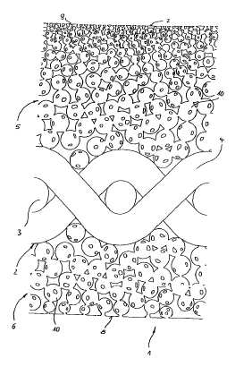
In the drawing the invention is further illustrated by way of a working
example
shown on a highly enlarged scale. It shows in cross-section a portion of a
material
strip 1. The material strip 1 comprises a support 2 in the form of a fabric
having
longitudinal filaments 3 and transverse filaments 4. On each of the upper and
the
underside of the support 2 a plastics layer 5, 6 is provided.
The first plastics layer S has been produced in accordance with the process of
the
invention in that a mixture of a plastics powder and soluble corpuscles has
been
sprinkled onto the support 2 and both jointly have been subjected to a thermal
and
pressure treatment. Due to this a homogeneous plastics layer 5 including
soluble
corpuscles substantially uniformly distributed therein has been produced, the
pressure treatment having resulted in a plane outer surface. Further soluble
particles were then sprinkled onto the still heated and therefore plastically
readily
deformable exposed side 7 of the plastics layer 5 and subsequently pressed by
means of pressure rollers or the like into the plastics layer S. The lower
plastics
layer 6 was dealt with in an analogous Fashion, in particular with regard to
the
' treatment of its outside 8.
CA 02214003 1999-11-17
12
Thereafter, the material strip 1 was subjected to a
treatment with a solvent for the soluble particles and
corpuscles. During this treatment the soluble particles pressed
into the exposed sides 7, 8 of the plastics layers 5, 6 were
first leached out, leaving behind embossments - for example
indicated by 9. These embossments 9, at least in part not only
communicate with one another but also with the soluble
corpuscles close to the outsides 7, 8 of the plastics layers 5,
6, so that the solvent can also reach those corpuscles and
dissolve them. The dissolution results in the formation of pore
cavities - as exemplified by 10 - in the plastics layers 5, 6,
having the configuration of the respectively leached out
corpuscles and inter-communicating with one another. This
provides a communication not only in a vertical direction but
because of the uniform distribution of the soluble corpuscles,
also in the horizontal direction. This provides a pore
structure similar to an open pore plastics foam, the pore
cavities coacting to form throughflow passages.
The pore cavities 10 of the plastics layer 5 on the
upper side now increase in size from the region of the exposed
side 7 towards the support 2. This may be brought about in that
initially a mixture of plastics particles and relatively large
soluble corpuscles and thereafter a further mixture of plastics
powder and by comparison smaller soluble corpuscles is applied.
CA 02214003 1999-11-17
12a
In the case of the plastics layer 6 on the underside a
plastics powder including even larger soluble corpuscles has
been used so that the pore cavities 10 are larger than those of
the plastics layer 5 on the upper side.