Language selection

Search

Patent 2214039 Summary

Third-party information liability

Some of the information on this Web page has been provided by external sources. The Government of Canada is not responsible for the accuracy, reliability or currency of the information supplied by external sources. Users wishing to rely upon this information should consult directly with the source of the information. Content provided by external sources is not subject to official languages, privacy and accessibility requirements.

Claims and Abstract availability

Any discrepancies in the text and image of the Claims and Abstract are due to differing posting times. Text of the Claims and Abstract are posted:

  • At the time the application is open to public inspection;
  • At the time of issue of the patent (grant).
(12) Patent: (11) CA 2214039
(54) English Title: ORCHARD BIN CORNERS AND JOINING BRACKETS
(54) French Title: COINS ET VERROUS D'ACCROCHAGE POUR CAISSES DE PRODUITS DE VERGER
Status: Expired
Bibliographic Data
(51) International Patent Classification (IPC):
  • B65D 6/26 (2006.01)
  • B65D 6/24 (2006.01)
(72) Inventors :
  • SCELSA, JOSEPH (Canada)
(73) Owners :
  • ADVANCE WIRE PRODUCTS LTD. (Canada)
(71) Applicants :
  • ADVANCE WIRE PRODUCTS LTD. (Canada)
(74) Agent: FETHERSTONHAUGH & CO.
(74) Associate agent:
(45) Issued: 2005-01-04
(22) Filed Date: 1997-08-27
(41) Open to Public Inspection: 1999-02-27
Examination requested: 2002-04-24
Availability of licence: N/A
(25) Language of filing: English

Patent Cooperation Treaty (PCT): No

(30) Application Priority Data: None

Abstracts

English Abstract

Orchard bins for the retail food sales industry have special corner members and joining brackets that allow assembly without the use of tools, and also permit disassembly for storage. The connector system for interconnecting two panels together has a connector member with a first surface for positioning on one panel vertical strip and a second surface for positioning on a second panel vertical strip. The first surface and the second surface of the connector member each have at least one cleat aperture thereon, and at least one cleat is provided for attachment to the first panel vertical strip and at least a further cleat for attachment to the second panel vertical strip, the cleats positioned to engage the cleat apertures in the first and second surfaces of the connector member.


French Abstract

Des caisses de produits de verger, destinées au secteur de la vente d'aliments au détail, comportent des éléments de coins et verrous d'accrochage spéciaux qui permettent un montage sans outil et un démontage à des fins de stockage. Le système de raccord servant à interconnecter deux panneaux ensemble comporte un élément de raccord avec une première surface servant à positionner une bande verticale de panneau et une deuxième surface servant à positionner une deuxième bande verticale de panneau. La première surface et la deuxième surface de l'élément de raccord ont chacune au moins une ouverture de crochet, et au moins un crochet sert à accrocher la première bande verticale de panneau et au moins un autre crochet sert à accrocher la deuxième bande verticale de panneau, les crochets étant positionnés de sorte à entrer en prise avec les ouvertures de crochet dans les première et deuxième surfaces de l'élément de raccord.

Claims

Note: Claims are shown in the official language in which they were submitted.


-9-


I CLAIM:

1. A connector system for interconnecting a first
panel and a second panel comprising:
a connector member having a first surface for
positioning on a first panel vertical strip and a
second surface for positioning on a second panel
vertical strip, the first surface and the second
surface of the connector member each having at least
one cleat aperture therein, and
at least one cleat for attachment to the first
panel vertical strip and at least a further cleat
for attachment to the second panel vertical strip,
the one cleat and the further cleat positioned to
engage the cleat aperture in the first surface and
the cleat aperture in the second surface of the
connector member.
2. The connector system according to claim 1
wherein the cleat includes a cleat base with
attachments to the first panel vertical strip or the
second panel vertical strip, a hook portion
extending from the cleat base for engagement in the
cleat aperture of the elongate connector member.


-10-
3. The connector system according to claim 2
wherein the hook portion includes a spaced portion
extending perpendicular from the cleat base joined
to a retaining portion substantially parallel to the
cleat base, the retaining portion having a tapered
distal end piece sloped away from the cleat base.
4. The connector system according to claim 1
wherein the connector member is an elongate corner
member with a first surface at an angle to the
second surface, and having a length approximately
the same height as the panel, the elongate corner
member having two cleat apertures therein to match
cleats at the top and bottom of the first panel
vertical strip and the second panel vertical strip.
5. The connector system according to claim 4
wherein the corner member has a generally V-shaped
cross-section with a first arm having the first
surface thereon and a second arm having the second
surface thereon, the first arm and the second arm
joining at a vertex and wherein a spine member
having a substantially Y-shaped cross-section
extends back from the vertex bisecting an angle
between the first arm and the second arm.


-11-
6. The connector system according to claim 5
wherein the angle between the first arm and the
second arm is 90°.
7. The connector system according to claim 5
wherein the corner member is formed of an aluminum
extrusion.
8. The connector system according to claim 2
wherein the cleat is formed of sheet steel.
9. The connector system according to claim 1
wherein the connector member is a joining bracket
with the first surface and the second surface
coplanar so the first panel and the second panel are
assembled substantially in line.
10. The connector system according to claim 9
wherein the cleat aperture of the joining bracket is
in the first surface and the second surface and
includes a notch with tapered edges to engage the
cleat.
11. The connector system according to claim 10
wherein the joining bracket is formed of sheet
steel.


-12-
12. The connector system according to claim 10
wherein the joining bracket has a channel-shaped
section extending generally perpendicular from the
bracket between the first surface and the second
surface, the channel-shaped section to receive a
crossbar.
13. A combination of a connector joining two panels
together comprising:
a first panel having a first vertical strip
adjacent a first panel side edge;
a second panel having a second vertical strip
adjacent a second panel side edge;
a connector member having a first surface
positioned on the first vertical strip of the first
panel and a second surface positioned on the second
vertical strip of the second panel, the first
surface and the second surface of the connector
member each having at least one cleat aperture
therein, and
at least one cleat attached to the first
vertical strip of the first panel and at least a
further cleat attached to the second vertical strip
of the second panel at a location such that the one


-13-
cleat and the further cleat each engage in the cleat
aperture to hold the first panel and the second
panel together with the connector member.
14. The combination according to claim 13 wherein
the cleat includes a cleat base with attachments to
the first panel vertical strip and the second panel
vertical strip, a hook portion extending from the
cleat base engaging in the cleat aperture of the
elongate connector member.
15. The combination according to claim 14 wherein
the hook portion includes a spaced portion extending
perpendicular from the cleat base joined to a
retaining portion substantially parallel to the
cleat base, the retaining portion having a tapered
distal end piece sloped away from the cleat base.
16. The combination according to claim 13 wherein
the connector member is an elongate corner member
with a first surface at an angle to the second
surface, and having a length approximately the same
height as the panel, the elongate corner member
having two cleat apertures therein connected to two
cleats in each of the first vertical strip of the
first panel and the second vertical strip of the
second panel.


-14-
17. The combination according to claim 16 wherein
the corner member has a generally V-shaped cross-
section with a first arm having the first surface
thereon and a second arm having the second surface
thereon, the first arm and the second arm joining at
a vertex and a spine member having a substantially
Y-shaped cross-sectional extends back from the
vertex bisecting an angle between the first arm and
the second arm.
18. The combination according to claim 13 wherein
the connector member is a joining bracket with the
first surface and the second surface coplanar so the
first panel and the second panel are substantially
in line.
19. The combination according to claim 18 wherein
the cleat aperture of the joining bracket is in the
first surface and the second surface and includes a
notch with tapered edges to engage the cleat.
20. The combination according to claim 19 wherein
the joining bracket has a channel-shaped section
extending generally perpendicular from the bracket
between the first surface and the second surface,
the channel-shaped section to receive a crossbar.

Description

Note: Descriptions are shown in the official language in which they were submitted.


CA 02214039 1997-08-27
ORCHARD BIN CORNERS AND JOINING BRACKETS
The present invention relates to bins and more
specifically to bins that can be assembled using corner
members and joining brackets with standard sized panels.
Quick connection cleats on the panels attach to the
corner members and joining brackets.
In the retail food sales industry there is a need
for bins to store and display produce. Most bins are
made so that they can be assembled and disassembled, thus
they can be used at different store locations and at
different times of the year. When the bins are not
needed, the components can be stored. Present designs
for orchard bins generally use removable brackets with
panels. Tools are required to attach and detach the
brackets to the panels which can be time consuming if a
particular tool is missing. Some designs overcome the
use of tools by using metal straps with hand-locking
bolts to secure the panels together. Such bins are still
time consuming to assemble and disassemble and
furthermore the panels cannot generally be joined
together in an infinite number of ways to provide larger
or smaller bins. There is a need for a system of
connecting standard sized panels to form bins of varying
sizes that is both relatively quick and easy to assemble


CA 02214039 1997-08-27
- 2 -
and disassemble and does not require the use of special
tools.
It is an aim of the present invention to provide
orchard bin corner members and joining brackets that can
be used with substantially standard sized panels to
assemble different sizes of bins. Both the corner
members and the joining brackets have cleat apertures
therein and cleats are attached to inside faces of the
panels which engage in the apertures either in the corner
members or in the joining brackets to join the panels
together and form a bin.
The present invention provides a connector system
for interconnecting a first panel and a second panel
comprising a connector member having a first surface for
positioning on a first panel vertical strip and a second
surface for positioning on a second panel vertical strip,
the first surface and the second surface of the connector
member each having at least one cleat aperture therein,
and at least one cleat for attachment to the first panel
vertical strip and at least a further cleat for
attachment to the second panel vertical strip, the one
cleat and the further cleat positioned to engage the
cleat aperture in the first surface and the cleat
aperture in the second surface of the connector member.


CA 02214039 1997-08-27
- 3 -
The present invention also provides a combination of
a connector joining two panels together comprising a
first panel having a first vertical strip adjacent a
first panel side edge, a second panel having a second
vertical strip adjacent a second panel side edge, a
connector member having a first surface positioned on the
first vertical strip of the first panel and a second
surface positioned on the second vertical strip of the
second panel, the first surface and the second surface of
the connector member each having at least one cleat
aperture therein, and at least one cleat attached to the
first vertical strip of the first panel and at least a
further cleat attached to the second vertical strip of
the second panel at a location such that the one cleat
and the further cleat each engage in the cleat aperture
to hold the first panel and the second panel together
with the connector member.
In drawings which illustrate embodiments of the
present invention,
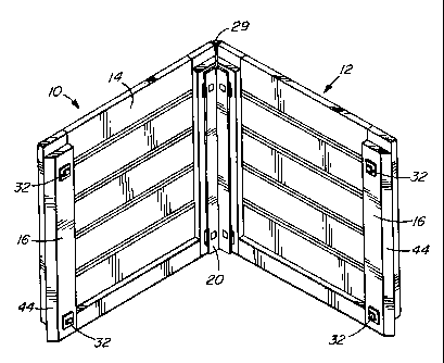
Figure 1 is an isometric view showing two panels
joined with a corner member according to one embodiment
of the present invention,
Figure 2 is a cross-sectional view showing the
corner member of Figure l,


CA 02214039 1997-08-27
- 4 -
Figure 3 is an isometric view showing the corner
member of Figure 1,
Figure 4 is a side view showing a cleat according to
one embodiment of the present invention,
Figure 5 is an elevational view showing the cleat of
Figure 4,
Figure 6 is an isometric view showing the joining
bracket for connecting panels together in line according
to another embodiment of the present invention,
Figure 7 is an elevational view showing the joining
bracket of Figure 6.
Orchard bins are generally made of a series of
identical sized panels that are joined together by the
connectors of the present invention. As shown in Figure
l, a first panel 10 and a second panel 12 each have a
series of horizontal boards 14 with vertical side strips
16 on each side. In the embodiments shown, the side
strips 16 act as reinforcing for the horizontal boards 14
to form the panel 10. The construction of these panels
does not form part of the present invention.
Figure 1 illustrates an elongate corner member 20
shown in more detail in Figures 2 and 3. The corner


CA 02214039 1997-08-27
_ 5 _
member 20 is preferably formed of an aluminum extrusion
and has two arms 22 arranged in a V-shape extending from
a vertex 24. A Y-shaped brace member 26 extends back
from the vertex 24 away from the two arms 22 bisecting
the angle between the arms 22. As shown in Figure 3, a
small angle 28 at the end of the brace member 26 extends
up above the top of the corner member 20. In effect the
small angle 28 extends to the top of the panels 10,12 as
shown in Figure 1. As can be seen in Figure 1, the
vertical side strips 16 do not extend up to the top of
the panels 10,12 and thus the corner member 20 terminates
just prior to the top of these vertical side strips 16.
The elongate corner member 20 has two cleat
apertures 30 in both arms 22. These cleat apertures 30
are positioned to engage with cleats 32 as attached to
the panels 10,12 shown in Figure 1. The cleats 30 are
attached directly to the vertical side strips 16 of the
panels. The cleats 30 are all positioned at the same
position on the vertical side strips 16 for all the
panels 10. Thus all corner members 20 can be locked to
all panels 10. Details of the cleats 32 are shown in
Figures 4 and 5. The cleat 32 comprises a base plate 34
which is substantially rectangular and has four
attachment holes 36 in the corners for attachment to the
vertical side strips 16 of the panels 10. Screws, bolts
or other attachment devices may be used for connecting
the cleats 32 to the vertical side strips 16 of the


CA 02214039 1997-08-27
- 6 -
panels 10. In another embodiment the base plates 34 can
be attached by adhesive or other suitable fastening
devices.
The cleat 32 has a hook member which has a
perpendicular portion 38 extending out from the base
plate 34 of the cleat 32 and a flat vertical portion 40
parallel to the base plate 34 which extends up and has
tapered ends and a distal end piece 42 sloped away from
the base plate 34 to provide a guide for guiding the
cleat 32 to engage in the arm 22 of the corner member 20
through the cleat aperture 30.
The panels 10 are arranged to have the cleats 32
attached to the vertical side strips 16 on both sides
and, thus the cleats 32 become an integral part of each
panel 10. In order to join the panels 10 together in a
corner configuration, as shown in Figure 1, the panels 10
are first all placed together and the corner member 20 is
then pushed into place between the ends of the two panels
10. In the embodiment shown the vertical side strips 16
have bevelled edges 44 which fit against the surface of
the corner brace member 26. The small angle 28 holds a
rounded plastic corner piece 29 for a rounded flush
exterior corner. As the corner member 20 is pushed down
between the panels 10, the cleat apertures 30 in the
corner members 20 pass over the cleats 32, the cleats 32
then pass through the cleat apertures 30 and as the


CA 02214039 1997-08-27
corner member 20 is pushed downwards the cleats 30 engage
the arms 22 directly above the cleat apertures 30 and the
panels are held in a corner configuration as shown in
Figure 1.
If it is a matter of making a bin with four panels,
then four corner members 20 are provided for each of the
four corners and the bin is assembled by installing the
four corner members 20.
In another embodiment it may be necessary to make a
bin which has two or three panels per side in which case
it is necessary to join the panels 10 together so that
they are coplanar. In order to do this a joining bracket
46, as shown in Figures 6 and 7, is provided. The
joining bracket 46 is made of a flat steel plate 48
having sufficient length to span between two panels 10
when placed side-by-side in coplanar relationship. The
plate 48 has notches 50 at each side with tapered
openings 52 as shown in Figure 7. These notches 52
represent the cleat openings and, as shown in Figure 6,
engage with the two cleats 32 positioned on adjacent
panel vertical side strips 16. As the panels 10 have
cleats 32 at both the top and bottom of the vertical side
strips 16, then two joining brackets 46 are provided to
join panels 10 together in a coplanar arrangement.


CA 02214039 1997-08-27
_ g _
In the center of the plate 48 of the joining bracket
46 is attached a channel section 54, preferably welded to
the plate 48 and extending out away from the panels 10.
The channel section 54 holds a crossbar 56 which is
preferably wood, steel or the like. Holes 58 in the
channel section 54 are provided for screws, welds, rivets
or the like to attach the crossbar 56 in the channel
section 54.
The corner member 20 is preferably extruded
aluminum. The other members, the cleat 32 and the
joining bracket 46, are preferably made of sheet steel,
although other materials such as aluminum, plastic and
the like may be used. It will be understood that by
using the joining brackets 46 several panels 10 may be
assembled side-by-side in both directions. Crossbars 56
extend across the top of the panels and are held to the
joining brackets 46. The crossbars 56 have the same
length representing the number of panels that are in the
side parallel to the crossbars 56. The bin may be made
square or rectangular as desired.
Various changes may be made to the embodiments shown
herein without departing from the scope of the present
invention which is limited only by the following claims.

Representative Drawing
A single figure which represents the drawing illustrating the invention.
Administrative Status

For a clearer understanding of the status of the application/patent presented on this page, the site Disclaimer , as well as the definitions for Patent , Administrative Status , Maintenance Fee  and Payment History  should be consulted.

Administrative Status

Title Date
Forecasted Issue Date 2005-01-04
(22) Filed 1997-08-27
(41) Open to Public Inspection 1999-02-27
Examination Requested 2002-04-24
(45) Issued 2005-01-04
Expired 2017-08-28

Abandonment History

There is no abandonment history.

Payment History

Fee Type Anniversary Year Due Date Amount Paid Paid Date
Registration of a document - section 124 $100.00 1997-08-27
Application Fee $150.00 1997-08-27
Maintenance Fee - Application - New Act 2 1999-08-27 $50.00 1999-07-12
Maintenance Fee - Application - New Act 3 2000-08-28 $50.00 2000-08-10
Maintenance Fee - Application - New Act 4 2001-08-27 $50.00 2001-08-17
Maintenance Fee - Application - New Act 5 2002-08-27 $150.00 2002-04-03
Request for Examination $400.00 2002-04-24
Maintenance Fee - Application - New Act 6 2003-08-27 $150.00 2003-06-02
Maintenance Fee - Application - New Act 7 2004-08-27 $200.00 2004-04-30
Final Fee $300.00 2004-10-21
Maintenance Fee - Patent - New Act 8 2005-08-29 $200.00 2005-04-15
Maintenance Fee - Patent - New Act 9 2006-08-28 $200.00 2006-04-03
Expired 2019 - Corrective payment/Section 78.6 $300.00 2007-01-18
Maintenance Fee - Patent - New Act 10 2007-08-27 $250.00 2007-05-11
Maintenance Fee - Patent - New Act 11 2008-08-27 $250.00 2008-07-30
Maintenance Fee - Patent - New Act 12 2009-08-27 $250.00 2009-07-27
Maintenance Fee - Patent - New Act 13 2010-08-27 $250.00 2010-05-04
Maintenance Fee - Patent - New Act 14 2011-08-29 $250.00 2011-03-22
Maintenance Fee - Patent - New Act 15 2012-08-27 $450.00 2012-03-23
Maintenance Fee - Patent - New Act 16 2013-08-27 $450.00 2013-06-20
Maintenance Fee - Patent - New Act 17 2014-08-27 $450.00 2014-08-22
Maintenance Fee - Patent - New Act 18 2015-08-27 $450.00 2015-05-28
Maintenance Fee - Patent - New Act 19 2016-08-29 $450.00 2016-06-01
Owners on Record

Note: Records showing the ownership history in alphabetical order.

Current Owners on Record
ADVANCE WIRE PRODUCTS LTD.
Past Owners on Record
SCELSA, JOSEPH
Past Owners that do not appear in the "Owners on Record" listing will appear in other documentation within the application.
Documents

To view selected files, please enter reCAPTCHA code :


To view images, click a link in the Document Description column. To download the documents, select one or more checkboxes in the first column and then click the "Download Selected in PDF format (Zip Archive)" or the "Download Selected as Single PDF" button.

List of published and non-published patent-specific documents on the CPD .

If you have any difficulty accessing content, you can call the Client Service Centre at 1-866-997-1936 or send them an e-mail at CIPO Client Service Centre.


Document
Description 
Date
(yyyy-mm-dd) 
Number of pages   Size of Image (KB) 
Representative Drawing 1999-03-22 1 11
Claims 1997-08-27 6 158
Description 1997-08-27 8 249
Drawings 1997-08-27 4 98
Abstract 1997-08-27 1 22
Cover Page 1999-03-22 1 57
Drawings 2002-04-24 3 65
Representative Drawing 2004-12-01 1 22
Cover Page 2004-12-01 1 50
Assignment 1997-08-27 4 145
Correspondence 2001-08-17 1 30
Prosecution-Amendment 2002-04-24 1 30
Prosecution-Amendment 2002-04-24 5 111
Fees 2003-06-02 1 37
Fees 2000-08-10 2 73
Correspondence 2004-10-21 1 27
Fees 2005-04-15 1 36
Fees 2002-04-03 1 39
Fees 2006-04-03 1 36
Fees 2004-04-30 1 38
Prosecution-Amendment 2007-01-18 2 62
Correspondence 2007-01-26 1 15
Fees 2007-05-11 1 36
Fees 2010-05-04 1 38
Fees 2011-03-22 1 36
Fees 2012-03-23 1 67
Fees 2013-06-20 2 77
Fees 2014-08-22 2 85
Maintenance Fee Payment 2016-06-01 2 80