Note: Descriptions are shown in the official language in which they were submitted.
CA 02214047 1997-08-27
WO 96/27072 PCT/L1S96/02707
- 1 -
Description
Method of Cutting and Cutting Rotative Bit
Technical Field
The present invention generally relates to a
method and design of cutting and cutting rotative
bits, which can be used for excavation, planing and
drilling of rock and soil and other non-metallic
brittle materials, for destruction, production and
treatment of construction materials, and which can
l0 be mounted on corresponding equipment, intended for
cutting and crushing of the above mentioned
materials.
Background Art
Generally, the cutting process mechanism is as
shown in FIG. 1. Cutting of a material, like rock,
is carried out due to thrust force T and normal
component C" of the cutting force, generated by an
equipment drive. Under the action of these forces,
the tool simultaneously moves in horizontal and
vertical directions generating complicated stresses
that overwhelm rock resistance.
Under the action ~of the force C", distributed
over the bit front face, compressive stresses are
formed in the rock which are not large enough for
destruction but preload the rock to resist further
strain.
Under the action of the force T, shear stress
is produced in the rock due to the high level of
load concentration generated by the bit's cutting
edge. This shear stress provides generation and
development of destructive cracks in the brittle
material.
sugs-r~~-r~ sH~~ (RU-t~ 2s~
CA 02214047 1997-08-27
WO 96/27072 PCT/IJS96/02707
- 2 -
1 At the same time, both forces C~ and T
generate a confined zone of superpressurized rock,
located next to the bit cutting edge. This so-
called kernal is an accumulator of energy which can
discharge in an explosive way when accumulated
energy exceeds ultimate rock resistance.
Because the previously mentioned destructive
cracks propagate from the cutting edge in the
direction of lowest resistance, they initially tend
toward the open surface of the rock. However,
these cracks cannot bypass the enhanced resistance
of the volume of the rock compressed by
Consequently, the destructive cracks pass around
the compressed rock and reach the open surface at
a distance L from the bit front face, isolating the
stressed volume of rock and separating this chip
from the entire rock massif.
Under continuous, combined action of
compressive and shear stresses, successive rock
chips are separated from the rock mass in a whole
or nearly whole condition chiefly due to long,
active destructive cracks and kernal explosion
after sufficient energy is accumulated to overcome
the crack shortfall.
Therefore, in an effective rock cutting
process, it is necessary to maintain a significant
load concentration at the bit cutting edge. This
is provided by a positive relief angle 6 of the bit
so that normal force, T, acts only on a thin line
of contact between rock and bit cutting edge. This
line contact is critical since cutting ability
degrades rapidly with relatively small wear in this
area. A sizeable width to this contact area
greatly decreases stress concentration in the rock
and greatly inhibits long crack generation.
CA 02214047 1997-08-27
WO 96/27072 PCTIUS96/02707
- 3 -
1 The effective cutting bit must have an optimal
A
combination of high cutting ability and high
durability of the cutting element, reliable
protection from overloading, preservation of the
bit positive relief angle, and maintenance of other
initial parameters throughout the lifetime of the
cutting bit.
A plurality of tools have been developed with
the objective of achieving some of the above
mentioned qualities.
The first group of rock-destructing tools is
comprised of cutting bits with non-rotatable
cutting elements. U.S. Patent 1,174,433 discloses
a non-rotating cutter which has a convex front
face. But it has a positive rake angle; the angle
between its longitudinal axis and the cut (treated)
surface behind a bit (defined as attack angle) is
less than 90°. It has a short cutting edge,
positive rake angle and small included angle.
Compared to the present invention, this bit has low
durability and wear resistance and it only can be
used for destruction of the soft and not abrasive
rock.
U.S. Patents 4,538,691 and 4,678,237 disclose
non-rotating cutting tools having rock-destructing
elements with a flat front face and substantial
negative rake angle, providing protection of the
bit from overloading due to operation of a lifting
force. However, the described bit has a low
cutting ability and requires significant thrust
force for penetration into rock. Its attack angle
does not exceed 90°.
U.S. Patent 4,538,690; 4,558,753 and 4,593,777
disclose non-rotating cutting bits, having a rock-
destructing element with a concave front face,
CA 02214047 1997-08-27
WO 96/27072 PCT/US96102707
- 4 -
1 oriented at a large negative rake angle, which is
used to increase bit durability (including
protection against overload). However, this bit ,
also has low cutting and penetration ability. The
bit is oriented at an attack angle that is less
than 90°.
The second group of patented rock-destructing
tools is comprised of round bits with symmetrical
cutting elements, which can rotate around its own
longitudinal axes.
In the first sub-group of these rotating
tools, the bits' rock-destructing elements have a
conical shape (direct cone) and destroy rock by
their convex-shaped back faces, as disclosed, for
example, in U.S. Patent 3,650,656 3,807,804 and
4,804,231. Russian Patent 1,671,850-A1 discloses
the same so-called conical bit type, which has
limited contact area, dependent on attack angle,
that can be changed from 0 to 90°. Described bits
are of a crushing type that operate without
generation of long destructive cracks. The bits
are oriented at an attack angle which does not
exceed 90° . They have convex front and back faces;
zero or negative relief angle and positive rake
angle. Their self-rotation is not reliable.
Therefore they cannot self-sharpen. These bits
have significantly higher specific energy
requirements for rock destruction compared to the
present invention.
The second sub-group of the rotatable tools
includes bits, which destroy rock by their front
faces, as disclosed, for example, in U.S. Patent
5,078,219. This bit has a convex back face,
positive relief angle and an attack angle close to
zero. The bit is a cutting tool when its cutting
CA 02214047 1997-08-27
WO 96/27072 PCT/US96/02707
- 5 -
1 edge is a sharp one. However, the bit design does
not protect it against fast dulling. Bit self-
sharpening is impossible since there is no
correction of the bit's worn area. As discussed
4 previously, a sizeable width of this contact area
for normal force, T, greatly reduces cutting
ability.
The third sub-group of the rotatable tools is
represented by chisel bits, as disclosed, for
example, in German patents 3,336,154-Al and
3,234,521-A1. These bits have a replaceable
cutting sleeve of a tubular chisel shape with a
sharpened front end. The bits have a rather small
included angle, a sizeable positive rake angle and
a small relief angle. Therefore, these bits have
low durability and wear resistance and they can
only be applied for destruction of soft, not
abrasive rock. Compared to the present invention,
the bits have an attack angle much less than 90,
a front face which is concave, a back face which
is
convex, and the bit cannot self-sharpen.
Disclosure of Invention
Accordingly, it is an object of the present
invention to provide a method of cutting and a
cutting rotative bit, which avoids the
disadvantages of the prior art.
More particularly, it is an object of the
present invention to provide a method of cutting
and a cutting rotative bit which ensures high
durability and maintenance of the bit's high
initial cutting ability for the entire service
life, independent of normal bit wear along
engagement surfaces.
In keeping with these objects and with others
which will become apparent hereinafter, one feature
CA 02214047 1997-08-27
WO 96/27072 PCT/US96/02707
- 6 -
1 of the present invention resides, briefly stated,
in a method of cutting in accordance with which a
cutting rotative bit is used with a body and a
generally circular cutting element or multiple
elements, connected with the body wherein the
cutting element has a convex front face, and in the
inventive method the cutting rotative bit is
oriented so that an attack angle of the bit's
cutting element exceeds 90°. (Attack angle is the
angle between the longitudinal axis of the bit and
the cut surface behind the bit).
When the method is performed and the tool is
designed in accordance with the present invention,
the following advantages are provided:
- Significant cutting ability of the bit,
which provides highly efficient
destruction of the rock and other
similar material;
- Continuous, forced self-rotation of the
bit around its own longitudinal axis,
which provides increased bit cutting
edge length and uniform wear along its
back face:
- Continuous, forced self-sharpening of
the bit, that maintains the initial
positive relief angle, of the bit along
its whole cutting edge by grinding away
interfering cutting element material
along its back face:
- Increased durability of the bit
resulting in high bit reliability and
longevity and increased range of working
material that may be engaged because of
highly rational force transmission
through the cutting element of the bit.
CA 02214047 1997-08-27
WO 96/27072 PCT/US96/02707
_ 7
1 Stress in the brittle cutting element is
almost entirely compressive;
- Effective operation of the bit until a
large proportion of the cutting element
is consumed by normal wear providing
long bit service life.
The novel features which are considered as
characteristic for the invention are set forth in
particular in the appended claims. The invention
itself, however, both as to its construction and
its method of operation, together with additional
objects and advantages thereof, will be best
understood from the following description of
specific embodiments when read in connection with
the accompanying drawings.
Brief Decription of the Drawincts
FIG. 1 is a view schematically showing the
mechanism of rock destruction;
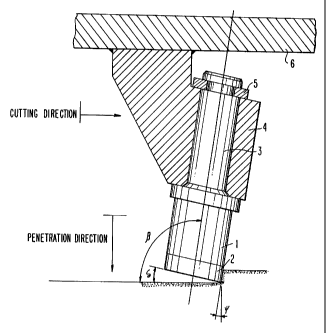
FIG. 2 is a view, showing a cutting device
provided with the cutting rotative bit in
accordance with the present invention;
FIG. 3a is a view, showing the inventive
cutting rotative bit with cutting element, having
the front face of a cylindrical shape and back face
of a flat shape;
FIG. 3b is a view, showing the inventive
cutting rotative bit with cutting element, having
the front face of an inverse conical shape and back
face of a flat shape;
FIG. 3c is a view, showing the inventive
cutting rotative bit with cutting element, having
the front face of a direct conical shape and a back
face of a flat shape;
FIG. 3d is a view, showing the inventive
cutting rotative bit with cutting element, having
CA 02214047 1997-08-27
WO 96/27072 PCT/US96/02707
- g -
1 the front face
of a cylindrical
shape and a back
face of a concave
shape;
FIG. 3e is a view, showing the inventive
cutting rotative bit with cutting element, having
the front face
of a cylindrical
shape and a back
face of a convex shape;
FIG. 4a is a view, showing the inventive
cutting rotative bit with a simple cutting element
on a cylindrical bit body;
FIG. 4b is a view, showing the inventive
cutting rotative bit with multiple cutting elements
on a stepped cylindrical
body;
FIG. 4c is a view, showing the inventive
cutting rotative bit with cutting element, having
the round smooth shape in cross-section;
FIG. 4d is a view, showing the inventive
cutting rotative bit with cutting element, having
the polygonal
shape in cross-section;
FIG. 4e is a view,
showing the inventive
cutting rotative bit with cutting element, having
a daisy shape cross-section;
in
FIG. 5a is a plan view of the inventive
cutting rotative bit, showing skew angle;
FIG. 5b is a view,
showing the main
longitudinal section
of the cutting
rotative bit
and all vertical plane angles in accordance with
the present invention;
FIG. 5c is a view, showing cross-section of
the inventive
cutting rotative
bit; and
FIG. 6 is a perspective view of the inventive '
cutting rotative bit while cutting.
Best Mode of Carrying Out the Invention
A cutting tool (FIGS. 2, 3 and 4) in
accordance with the present invention has a body
which is identified with reference numeral 1 and a
CA 02214047 1997-08-27
WO 96/27072 PCT/US96/02707
_ g _
1 cutting element or an insert which is identified
with reference numeral 2. The body is further
provided with a tail part 3 which contributes to
rotation of the bit about its longitudinal axis and
can be used to hold the cutting tool.
As can be seen from FIG. 2, the tail part of
the bit is arranged in a tool holder 4 and retained
by a retainer 5. The tool holder or a plurality of
tool holders are aligned with respect to each other
and attached to a cutter support 6. The main
angles, providing the spatial orientation of each
cutting rotative bit, are determined by mounting of
the tool holder to the cutter support as will be
discussed hereinbelow. The tail portion 3 of the
bit and therefore the cutting rotative bit are held
in the tool holder rotatably around its
longitudinal axis and fixed in the axial direction.
The cylindrical or conical body is made, as a
rule, from alloyed steel, which has a substantial
elasticity and strength.
The insert 2 (FIG. 3) is ring-shaped and can
be formed as a solid ring or a composite ring,
composed of individual segments. The inner opening
of the ring can be cylindrical or conical while its
surface, which is in contact with the body, may be
flat or curved. In other embodiments of this'
invention, the entire bit can be exclusively made
of one material.
The upper surface of the insert can be flat,
as shown in FIGS. 3a, 3b, 3c. It can also be
concave, as shown in FIG. 3d or convex " as shown
in FIG. 3e. The outer surface of the ring which is
the front face of the bit always has a convex shape
formed by a generatrix of a cylinder, as shown in
FIGS. 3a, 3d, and 3e, or direct cone, as shown in
CA 02214047 1997-08-27
WO 96/27072 PCT/LTS96/02707
- 10 -
1 FIG. 3c or inverse cone, as shown in FIG. 3b.
Outer contour of the cutting element can be
straight one, as shown in FIG. 4a, or stepped one, .
as shown in FIG. 4b.
Shape of the cutting element in cross-section
can be round, as shown, in FIG. 4c, or polygonal,
as shown in FIG. 4d, or daisy-shaped, as shown in
FIG. 4e.
The insert, as a rule, is made of hard wear
resistant materials, preferably sintered hard
alloys of the tungsten carbide group. The convex
shape of the front face ofthe insert is preferable,
since the cutting forces are directed toward the
center of the ring and are resolved into mainly
safe compressive stresses, instead of tensile
stresses which are very dangerous for brittle
materials like the hard alloys the insert is
composed of.
The convex shape of the front face of the bit
also contributes to more efficient removal of the
destroyed rock from the cutting zone due to
dispersing of cuttings to both sides of the bit.
The connection of the insert to the body can
be performed by brazing, in particular for the
composite ring, with use of high temperature
brazing filler metal, or performed with
interference for press fit. The ring-shaped insert
provides semi-closed containment of brazing
materials to ensure durable and reliable j oining of
the body and insert which is particularly important '
in condition of dynamic loads. The press fitting
on the other hand, eliminates residual thermal
stresses which are characteristic of high
temperature brazing due to different expansion
coefficients of the joined elements.
CA 02214047 1997-08-27
WO 96/27072 PCTIUS96102707
- 11 -
1 The solid bits which are not subdivided into
the body and insert are recommended for cutting of
non-abrasive materials. It must be subjected to a
special thermal treatment, for example, isothermic
quenching to provide different hardness of the body
portion and cutting element portion of the bit.
The main new feature of the present invention
is that the inventive method is performed so that
the cutting rotative bit is oriented to the surface
of the rock to be cut at an attack angle Q which
exceeds 90°, a shown in FIGS. 2 and 5b.
Skew angle a shown in FIGS. 5a and 5c, is
measured in the plane of the cut rock surface and
is the angle between the projection of the bit
longitudinal axis and the direction of bit motion.
The skew angle determines a cutting force C,
providing the rock cutting (C - Q cos a) and
rotating (crushing) force Q,,ot, promoting rotation
of the bit around its own longitudinal axis
2 0 Q~ot - Q s in a ) .
The tool attack angle Q, in combination with
tool skew angle a provides favorable conditions for
optimization of the main parameters of the tool
(including a rake angle ~r and a relief angle d of
the bit cutting edge).
The spatial orientation of the tool which is
determined by attack angle /3 and skew angle cx
imparts the following properties:
- The front face of the bit is the convex
surface of the insert, while the back
face of the tool is the end surface of
the insert;
- The rotation of the tool around its
longitudinal axis (FIGS. 5b and 5c)
occurs due to rolling of the bit cutting
CA 02214047 1997-08-27
WO 96/27072 PCT/US96/02707
- 12 -
1 edge along the corresponding surface of
the rock under the action of the rotary
moment Moot ~ Mr.ot is the couple of the .
frictional force generated by force Q~ot
(and thrust force) and tangential force Q.
- The direction of the rectilinear motion
of the tool does not coincide with the
direction of cutting (breaking) of the
rock, which is different for each point
of the cutting edge of the tool, as
shown in FIG. 5c.
- Instantaneous values of rake angle Sri and
a relief angle 6i vary contiously from
point to point along bit cutting edge
(arc AE, FIG. 5c).
At the point B (FIG. 5c) the relief angle 6b
has its maximum positive value. Moving away from
the point B to the right and to the left, this
angle reduces (sin 6i = sin Sb cos Ei) and assumes
its zero value at point D and a negative value at
point E. The geometrical correction of the relief
angle of the tool by introducing the positive angle
06 (FIG. 5b: D6 = cos R sin a) provides a positive
relief angle along the whole cutting edge of the
bit (the arc AE in FIG. 5c). Therefore, this
condition, necessary for high rock stress
concentration at the cutting edge, is maintained.
Under the condition ~ DS ~ - ~ 6e ~ , the relief
angle of the tool at the point E is zero.
Therefore, on the radial line at E, self-sharpening -
occurs because of continuous removal of back face
material that would interfere with maintaining the '
positive relief angle along the entire cutting
edge. Self-sharpening proceeds around point E at
the same time as wear occurs along the remainder of
SUBSTITUTE SHEET (RULE 26~
CA 02214047 1997-08-27
WO 96/27072 PCT/US96/02707
- 13 -
1 the cutting edge.
At the point B in FIG. 5c, the rake angle orb
has its maximum negative value. Moving from point
B to the right or to the left increases this angle
so as to assume its zero value at the point D and
its positive value at the point E. Therefore, at
the point E the thrust force per unit length will
be maximal, when compared with remaining points of
the cutting edge of the tool over the arc AE in
FIG. 5c. Therefore, the intensity of friction and
wear is maximum at E and, in combination with the
zero value of the relief angle, provides conditions
which are close to machine tool sharpening. With
the introduction of the positive angle of
correction O~r, FIG. 5b, the effect of self-
sharpening is further increased.
The negative rake angle of the tool, which is
maximal in central part of the cutting edge,
contributes to the self-protection against
overloading. A negative rake angle generates a
lifting force which lifts the tool from the rock.
Such overloading is usually caused by the increase
of the hardness of the rock to be broken.
The continuous rotation of the tool around its
longitudinal axis is reliable due to the following
factors
Absence of substantial resistance to the
rotation along the back face of the tool
due to the positive relief angle; and
- Use of substantial cutting force C (as
compared with the thrust force), which
is produced by the drive of the cutting
equipment to form the significant Q,.ot
The nature and the axial direction of wear of
the tool along the back face in combination with
~uesTi-rt~~-~ s~~~r c~t~~ ~~~
CA 02214047 1997-08-27
WO 96!27072 PCTlUS96/02707
- 14 -
1 the continuous renewal by self-sharpening to
initial values of the relief angle along the whole
cutting edge of the tool provides for efficient
operation of the tool in the cutting mode until the
wear substantially consumes the insert.
The attack angle in accordance with the
present invention can be within the range of 90 ° to
120°. The skew angle can be within the range of 5°
to 40°. The rake angle can be within the range of
plus 15° to minus 15°. The relief angle can be
within the range from 0 to 20 ° . The included angle
can be within the range of 50° to 100°.
While the invention has been illustrated and
described as embodied in a method of cutting and a
cutting rotative bit, it is not intended to be
limited to the details shown, since various
modifications and structural changes may be made
without departing in any way from the spirit of the
present invention.