Note: Descriptions are shown in the official language in which they were submitted.
CA 02214166 1997-08-27
A VEHICULAR LAMP AND METHOD
BACKGROiJND OF THE INVENTIOI~I
Field of the Invention
The present invention relates to a light fixture
for a vehicle and conversion method.
Description of Conventional Art
As illustrated in FIG. 1, conventional multi-
compartment vehicular lamps generally include a lens
assembly 1 which covers a housing member 2. The lamp
housing 2 typically supports a back-up function
incandescent lamp 3 (for indicating that the vehicle is
backing up) and a stop/tail/directional function
incandescent lamp 4 which are inserted in sockets 5 and
6, respectively (a stop function for indicating that
said vehicle has stopped, a tail function for
illuminating the back of said vehicle, and a
directional function for indicating which direction
said vehicle is turning). The sockets 5 and 6 are
connected by wires 7 and 8, respectively, to a power
source within the vehicle (not shown) to provide
illumination for a vehicle, as necessary. A suitable
connecting means may be employed for connecting housing
member 2 to a vehicle, and an electrical connecting
member electrically connects the vehicular lamp to an
electrical system of a vehicle. Conventional vehicular
rear lamps also may include a license plate
illuminating lamp, and the face of the lamp may include
a reflective surface portion for providing a reflex
rear reflector (not shown).
The lens assembly 1 typically includes a back-up
function lens 9 which covers the back-up function lamp
3 and a stop/tail/directional function lens 10 which
covers the stop/tail/directional function lamp 4. Of
course, the position of the lamps may vary, and the
number of functions (stop, tail, directional, back-up,
CA 02214166 1997-08-27
2
license plate) per lens or lamp may vary depending on
the type of vehicle.
Shortcomings of this conventional lamp assembly
include the short life of the multi-function
incandescent bulb, and a somewhat high power
consumption with resultant voltage drop.
There remains a need in the art for longer-lived
vehicular light fixtures, and methods for converting
conventional fixtures to longer-lived fixtures.
SIINIIKARY OF THE INVENTION
A light fixture for a vehicle comprises a housing
with a light-transmitting face divided into two
adjacent light-transmitting face portions, which
adjacent face portions are separate and discrete first
and second face portions. A light-emitting diode (LED)
array is positioned in the housing so as to emit light
from the first face portion, the LED array including a
plurality of adjacent rows of LEDs, each row of LEDs
including a plurality of adjacent LEDs. A first
electrical connector is provided for connecting the LED
array to an electrical system of the vehicle.so as to
transmit light from the LED array when the vehicle
running lights are on and when the vehicle is braking.
A light source is positioned in the housing so as to
emit light from the second face portion, and a second
electrical connector is provided for connecting the
light source to the electrical system of the vehicle so
- as to transmit light from the incandescent source when
the vehicle is backing up.
The invention is also applicable to conversion of
a conventional light fixture for a vehicle into a light
fixture as described above.
CA 02214166 1997-08-27
3
BRIEF DESCRIPTION OF THE DRAWINGS
FIG. 1 is a schematic front view of components of
a conventional vehicular lamp.
FIG. 2 shows a schematic front view of the first
step in producing a preferred embodiment of the present
invention, with a conventional lens used for
stop/tail/directional functions removed and the
corresponding incandescent lamp removed from its
socket.
FIG. 3 shows a schematic front view of how, in
accordance with a preferred embodiment of the present
invention, the lens assembly is changed from having a
conventional stop/tail/directional lens 10 as shown in
FIG. 3(a), to the conventional lens 10 being removed as
shown in FIG. 3(b), and finally, to a lens 210 being
placed into lens 1 as shown in FIG. 3(c).
FIG. 4 shows a schematic front view of how, in
accordance with a preferred embodiment of the present
invention, an LED stop/tail/directional lamp is
connected to the lamp housing.
FIG. 5 shows a schematic view opposite that of
FIG. 4 of the LED lamp being connected to the lamp
housing according to one embodiment of the present
invention.
FIG. 6 shows a schematic front view of one
embodiment of the present invention as fully assembled
with the lens assembly connected to the lamp housing.
FIG. 7 shows a schematic side view of one
embodiment of the present invention with the lens
assembly connected to the lamp housing.
FIG. 8 shows a schematic front view of another
embodiment.
FIG. 9 shows a schematic front view of a further
embodiment.
FIG. 10 shows a schematic view of electrical
wiring used in one embodiment of the present invention.
CA 02214166 1997-08-27
4
DETAILED DESCRIPTION OF THE PREFERRED EMBODIMENTS
In accordance with a method of the present
invention, a conventional light fixture for a vehicle
having only incandescent light sources can be converted
into a vehicular light fixture having an LED light
source.
With reference to FIG. 1, this method involves
modifying a first light fixture for a vehicle having a
housing 2 with a first light-transmitting face 1. Face
1 includes a first lens 10 for transmitting
incandescent light, and a first socket 6 for a first
incandescent lamp 4 in the housing 2 for connecting the
first lamp to an electrical system of the vehicle.
Lamp 4 transmits light when the vehicle running lights
are on, when the vehicle is braking, and for signaling
a vehicle turn. The first light-transmitting face 1 of
the conventional lighting fixture has a second lens 9
for transmitting incandescent light, a second socket 5
for a second incandescent lamp 3 in the housing 2, for
connecting the second lamp 3 to the electrical system
of the vehicle, to transmit light when the vehicle is
backing up.
The first socket 6 and first light-transmitting
face 1 are replaced with a second light-transmitting
face 1A and a light-emitting diode (LED) array 211,
shown in FIG. 6. The second light-transmitting face 1A
is divided into only two adjacent light-transmitting
face portions, which adjacent face portions are
separate and discrete first and second face portions
210 and 414, respectively. The second light-
transmitting'face 1A is connected to housing 2, as
shown in FIG. 7. The LED array 211 is positioned in
housing 2 so as to emit light from the first face
portion 210, the LED array including a plurality of
adjacent rows of LEDs 410, each row of LEDs including a
plurality of adjacent LEDs 412, as shown in FIG. 6. A
CA 02214166 2006-10-20
first electrical connector 209 is provided for
connecting the LED array to the electrical system of
the vehicle so as to transmit light from the LED array
lamp 204 when the vehicle running lights are on, when
5 the vehicle is braking, and for signalling a vehicle
turn. See FIG. 4. The second incandescent light source
3 emits light from the second face portion 414 when the
vehicle is backing up.
As shown in FIGS. 1 and 2, one method of producing
the present invention first involves removing the
conventional stop/tail/directional function lens 10,
the conventional stop/tail/directional function
incandescent lamp 4, and socket 6 from a conventional
vehicular lamp.
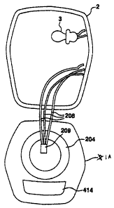
Next, as shown in FIG. 4, a stop/tail/directional
function LED lamp 204 is connected to wire 208 via an
interface electrical connector 209 and a
stop/tail/directional function LED lens 211 is inserted
into face 1A to cover the LED lamp 204. FIG. 5 shows
the same from the opposite side.
FIG. 3 shows a sequential front view of how, in
accordance with the preferred embodiment of the present
invention, face 1 is changed from having a conventional
stop/tail/directional function lens 10 as shown in FIG.
3(a), to the conventional lens 10 being removed to form
face 1' as shown in FIG. 3(b), and finally, to a
stop/tail/directional function LED lens 210 being
connected to face 1A as shown in FIG. 3(c).
FIG. 6 shows the present invention as fully
assembled with the face 1A for covering and connected
to the lamp housing 2, while FIG. 7 shows a side view
of the same.
The LED array shown in FIG. 6 is a substantially
circular array. In this embodiment, the LED array
includes a plurality of adjacent rows 410 of red LEDs,
each row 410 including a plurality of adjacent red LEDs
CA 02214166 1997-08-27
6
412. This embodiment further includes a partial row
411 of four red LEDs 413. In accordance with one
embodiment, all of LEDs 412 and 413 operate
continuously when the vehicle running lights are on,
but not always at the same intensity. In this
embodiment, partial row 411 of LEDs 413 operate at full
intensity continuously when the vehicle running lights
are on. The remaining LEDs 412 are connected with
the vehicle's electrical system so as to operate at
partial intensity when only the vehicle running lights
are on, and operate at full intensity only when the
vehicle is braking and/or signalling a turn. In
accordance with this embodiment, the turn signal
function of LED rows 411 override the stop function
when the vehicle is simultaneously signaling a turn and
braking. However, the LED configuration may vary with
lamp size or lens design in order to meet a desired
light output.
As shown in FIG. 6, the second face portion can be
a substantially linearly elongate area 414 for
transmitting substantially white light from the
incandescent light source when the vehicle is backing
up.
FIG. 7 shows an embodiment of the invention
wherein housing 2 contains a second light source 220
and an electrical connector 222 for connecting the
second light source to the electrical system of the
vehicle. Light source 220 operates at all times when
- the vehicle running lights are on and directs
illumination through a transparent window 224 in a
sidewall portion 226 of housing 2 so as to illuminate
an adjacent license plate of the vehicle. A reflector
228 is provided in housing 2 for directing the light
from source 220 through the side portion 226 of housing
CA 02214166 2006-10-20
7
2. In the embodiment shown, light source 220 is an
incandescent light source.
Another embodiment of the invention is shown in
FIG. 8, which includes an LED array 211 for
transmitting light when the vehicle running lights are
on, when the vehicle is braking and for signalling a
vehicle turn. According to this embodiment, a
substantially white LED array 230 is provided as the
light source for transmitting light when the vehicle is
backing up. FIG. 8 also shows an embodiment of the
invention wherein face 1B includes a reflective surface
232 for reflecting external light which impinges on the
reflective surface, thereby providing a reflex rear
reflector.
FIG. 9 shows still another embodiment of the
invention which includes a red LED array 234 for
transmitting light when the vehicle running lights are
on and when the vehicle is braking, a light source 236,
which can be an incandescent source or an LED source,
for transmitting light when the vehicle is backing up,
and a third face portion 238 comprising an amber LED
array for signalling a vehicle turn. FIG. 9
schematically shows a third electrical connector 240
for connecting the amber LED array 238 to the
electrical system of the vehicle for activation of the
amber LED array when signalling a vehicle turn.
FIG. 10 provides a schematic view of electrical
wiring which can be used to connect to a back-up light
source 3, 230, 236, license plate lamp 220, tail lamp
LEDs 410, and stop/turn LEDs 411, in accordance with
the present invention.
The present invention provides a light fixture for
a vehicle that incorporates a long-lived LED array for
the main vehicle rear light functions. The invention
also provides a method for converting a conventional
all-incandescent vehicle light fixture into a light
CA 02214166 1997-08-27
8
fixture including a long-lived LED array for the
vehicle's main rear light functions. Alternatively,
the inventive fixture can be assembled from all new
parts.
The invention having been thus described, it will
be apparent to those skilled in the art that the same
may be varied in many ways without departing from the
spirit and scope of the invention. Any and all such
modifications are intended to be included within the
scope of the following claims.