Language selection

Search

Patent 2214182 Summary

Third-party information liability

Some of the information on this Web page has been provided by external sources. The Government of Canada is not responsible for the accuracy, reliability or currency of the information supplied by external sources. Users wishing to rely upon this information should consult directly with the source of the information. Content provided by external sources is not subject to official languages, privacy and accessibility requirements.

Claims and Abstract availability

Any discrepancies in the text and image of the Claims and Abstract are due to differing posting times. Text of the Claims and Abstract are posted:

  • At the time the application is open to public inspection;
  • At the time of issue of the patent (grant).
(12) Patent: (11) CA 2214182
(54) English Title: IMPROVED BRAKE BEAM
(54) French Title: TRIANGLE DE FREIN AMELIORE
Status: Deemed expired
Bibliographic Data
(51) International Patent Classification (IPC):
  • B61H 13/36 (2006.01)
  • B61H 1/00 (2006.01)
  • F16D 65/06 (2006.01)
(72) Inventors :
  • SANDMANN, MICHAEL R. (United States of America)
  • BOBSEIN, LOUIS E. (United States of America)
(73) Owners :
  • MINER ENTERPRISES, INC. (United States of America)
(71) Applicants :
  • BUFFALO BRAKE BEAM COMPANY (United States of America)
(74) Agent: LAVERY, DE BILLY, LLP
(74) Associate agent:
(45) Issued: 2004-01-13
(22) Filed Date: 1997-08-28
(41) Open to Public Inspection: 1998-03-13
Examination requested: 2000-06-08
Availability of licence: N/A
(25) Language of filing: English

Patent Cooperation Treaty (PCT): No

(30) Application Priority Data:
Application No. Country/Territory Date
08/715,619 United States of America 1996-09-13

Abstracts

English Abstract

A brake beam assembly containing a compression member, a tension member, a strut connected to the tension member and the compression member, and two brake heads with recesses. The ends of the compression member and the tension member are disposed within the recesses of the brake heads together with two fasteners per recess; each of the fasteners is substantially perpendicular to the tension and compression members; and no other structural elements are present in the recesses.


French Abstract

Ensemble de triangle de frein contenant un organe de compression, un organe de tension, une jambe raccordée à l'organe de tension et à l'organe de compression, et deux porte-semelles de frein avec des évidements. Les extrémités de l'organe de compression et de l'organe de tension sont disposées au sein des évidements des porte-semelles de frein conjointement à deux fixations par évidement ; chacune des fixations est sensiblement perpendiculaire aux organes de tension et de compression ; et aucun autre élément structurel n'est présent dans les évidements.

Claims

Note: Claims are shown in the official language in which they were submitted.


We claim:

1. A brake beam assembly comprised of a compression member with a
first end and a second end, a tension member with a third end and a fourth
end, a strut connected to said tension member and said compression
member, a first brake head with a first recess, and a second brake head with
a second recess, wherein:

(a) said first end and said second end of said compression member
and said third end and said fourth end of said tension member are each
comprised of a first hole and a second hole extending completely through
each said end;

(b) said first end of said compression member and said third end of
said tension member are disposed within said first recess, and said second
end of said compression member and said fourth end of said tension member
are disposed within said second recess;

(c) disposed within each of said first hole is a first fastener, and
disposed within each of said second hole is a second fastener, wherein each
of said first fastener and said second fastener is disposed substantially
perpendicularly to said compression member and said tension member;

(d) disposed within said first recess is said third end of said tension
member, said first end of said compression member, a first fastener and a
second fastener;

(e) disposed within said second recess is said fourth end of said
tension member, said second end of said compression member, a first
fastener and a second fastener;
(f) said compression member comprises a first end surface and a
second end surface;

(g) said brake beam assembly is comprised of a first brake head
and a second brake head;
(h) said first brake head is contiguous with said first end surface of
said compression member; and

(i) said second brake head is contiguous with said second end
surface of said compression member.


5


2. The brake beam assembly as recited in claim 1, wherein said tension
member is comprised of a first parallel wall and a second parallel wall which
extend from a middle section to a first end section and a second end section,
provided that, when said first parallel wall and said second parallel wall
extend
past said section towards said first end section and said second end section,
said first parallel wall and said second parallel wall are substantially
straight
without any bends.

3. The brake beam assembly as recited in claim 1, wherein said assembly
is comprised of a first brake head and a second brake head, each of which is
under stress.

4. The brake assembly as recited in claim 1, wherein said strut is
contiguous with said tension member at a first point and a second point, and
wherein said strut is contiguous with said compression member at a third
point.

5. The brake assembly as recited in claim 2, wherein (a) said strut is
contiguous with said tension member at a first point and a second point, (b)
said strut is contiguous with said compression member at a third point, and
(c)
said first point and said second point are each located beyond said middle
section and on a substantially straight section.


6

Description

Note: Descriptions are shown in the official language in which they were submitted.


CA 02214182 2003-03-19
IMPROVED BRAKE BEAM
Field of the invention
A brake beam for use on railroad car trucks.
Background of the invention
Brake beams are well known to those in the art and have been
used with railroad car trucks for at least ninety years.
The prior art does not provide a brake beam structure which is
relatively light weight and, alsa, has relatively high static strength and
fatigue
resistance properties. It is an object of this invention to provide a
structure
with these properties and, additionally, having the properties of being
substan-
tially more durable and less likely to self-destruct during use.
Summan~ of the invention
A multi-piece brake beam assembly comprised of a rectilinear
compression member, a rectilinear tension member, strut means for
connecting the tension member and the compression member, a brake head
with a recess adapted so that the tension member and the compression
member may be partially located therein, and first and second fastening
means for fastening the tension rraember, the compression member, and the
brake head.
Although the preferred embodiment of this invention is illustrated
with regard to a hangerless brake beam, the invention is equally applicable to
a hanger type brake beam.
According to an aspect of the invention, a brake beam assembly
comprised of a compression member with a first end and a second end, a
tension member with a third end and a fourth end, a strut connected to the
tension member and the compression member, a first brake head with a first
recess, and a second brake head with a second recess, wherein:
(a) the first end and the second end of the compression
member and the third end and the fourth end of the tension
member are each comprised of a first hole and a second hole
extending completely through each said end;
1

CA 02214182 2003-03-19
(b) the first end of the compression member and the third end
of the tension member are disposed within the first recess, and
the second end of the Compression member and the fourth end
of the tension member are disposed within the second recess;
(c) disposed within each of the first hole is a first fastener, and
disposed within each of the second hole is a second fastener,
wherein each of the first fastener grad the second fastener is
disposed substantially perpendicularly to the compression
member and the tension member;
(d) disposed within the first recess is the third end of the
tension member, the first end of the compression member, a
first fastener and a second fastener;
(e) disposed within the second recess is the fourth end of the
tension member, the second end of the compression member, a
first fastener and a second fastener;
(f) the compression member comprises a first end surface
and a second end surface;
(g) the brake beam assembly is comprised of a first brake
head and a second brake head;
(h) the first brake head is contiguous with the first end
surface of the compression member; and
(i) the second brake head is contiguous with the second end
surface of the compression member.
Brief description of the drawings
The present invention will be more fully understood by reference
to the following detailed description thereof, wherein like reference numerals
refer to like elements, and wherein
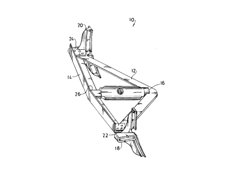
Figure 1 is first perspective view of one preferred embodiment
of the brake beam of this invention.
Figure 2 is a plan view of the brake beam unit of Figure 1.
Figures 3 and 4 are plan and side views, respectively, of tension
member 12.
1a

CA 02214182 1997-08-28
Figures 5, 6, and 7 are plan, front, and side views,
respectively, of compression member 14.
Figures 8 and 9 are side and top views, respectively,
of brake head 18.
Figure 10 is a perspective view of a brake beam strut.
Figure 11 is a plan view of the brake beam strut 16
disposed within the tension member 12.
Description of the preferred embodiments
Figure 1 is a perspective view of the brake beam unit
of this invention, which is comprised of a rectilinear tension
member 12, a rectilinear compression member 14, strut 16 joining
members 12 and 14, brake heads 18 and 20 with recesses (not shown)
within which members 12 and 14 partially nest, fasteners 22 and 24
which connect brake heads 18 and 20 to members 12 and 14, and a
fastener 26 (not clearly shown in Figure 1) connecting strut 16 to
compression member 14.
Figure 2 is a plan view of the brake beam unit 10. In this
embodiment, the unit has only two fasteners 23 per end.
Figure 3 is a plan view of tension member 12. In addi-
tion to having a constant width 96, tension member 12 preferably
is comprised of parallel walls 107 and 109, and 111 and 113 which,
when they extend past arcuate section 112 on either side, are sub-
stantially straight, without any bends.
Figure 4 is a side view of tension member 12. In the
embodiment depicted in Figures 3 and 4, tension member 12 has a
substantially "flat" cross-sectional shape. Upper surface 92 and
lower surface 94 are substantially parallel to each other, thereby
producing the desired flat structure 12 which consequently can be
within the recess (not shown) in brake head 18 and/or 20.
Walls 107 and 111 are cut to form notched sections 114
and 116. Tension member 12 is preferably symmetrical around its
midpoint 102, distance 102 is preferably at one-half of distance
100; and it is comprised of legs 108 and 110 which are integrally
2

CA 02214182 1997-08-28
connected to each other through arcuate section 112.
Figure 5 is a plan view of compression member 14, which
is preferably comprised of legs 126 and 128 (see Figure 7) which
extend through substantially its entire length 130. Legs 126 and
128 (see Figure 7) form a substantially ninety degree angle bet-
ween them. Referring again to Figure 5, compression member 14 is
preferably symmetrical around its midpoint 135, distance 133 is
preferably at one-half of distance 130. Compression member 14 is
comprised of end sections 132 and 134 which are partially disposed
within a recess (not shown) in each of brake heads 18 and 20(see
Figure 1). Referring to Figure 6, the end sections 132 and 134
preferably contain flat, substantially parallel surfaces 136,138
and 140,142 which are adapted to fit within such recess (not
shown). In the embodiment depicted, end compression member 14 is
comprised of a first section 146 and a second section 148. The
base leg 152 of section 146 is not coplanar with the base 154 leg
of section 148.
Referring to Figure 5, compression member 14 is prefer-
ably offset in two different directions which are orthogonal to
each other. Compression member 14 is comprised of upright leg 156
and upright leg 158, which are not coplanar with each other. Leg
158 has an offset (camber) 160 from leg 156.
Each of sections 146 and 148 are comprised of end walls 168
and 166 which are adapted to be substantially contiguous with cor-
responding surfaces (not shown) of brake heads 18 and 20.
Figures 8 and 9 are side and top views, respectively, of
brake head 18. Brake head 18 (and brake head 20) is comprised of
a recess defined by flat, parallel, inner surfaces 176 and 178
(Figure 8). Referring to Figure 9, tension member 12 is comprised
of linear surface 113 which, in part, abuts a portion of arcuate
surface 180. Because of the curved nature of surface 180, varying
the length of distance 72 of assembly 10 while keeping distance 88
constant (see Figure 2) will allow surface 180 to compensate for
such variation and to maintain substantially broad contact between
3

CA 02214182 1997-08-28
it linear surface 113. Surface 180 is also comprised of arc 182
which, when the assembly 10 under loaded conditions deflects, com-
pensates for such deflection.
Referring to Figures 8 and 9, brake head 18 is com-
prised of inner surface 184 which is adapted to receive surface
168 of compression member 14.
It will be seen from Figure 9 that fasteners 22 which
secure tension member 12 to brake head 20 are not colinear. Three
fasteners 22 are used in this assembly, although four or more fas-
teners also may be used. A welded joint (not shown) also may be
used.
Without wishing to be bound to any particular theory,
applicants believe that, under load, area 190 of compression mem-
ber 14 makes contact with the underside of area 192 of tension
member 12. Because of the nesting arrangement of members 12 and
14, this movement is limited.
Figure 10 is a perspective view of strut 16 which is
preferably comprised of slots 234, 236, 238, and 240, which are
adapted to engage the tension member 12 (see Figure 2). It will
also be seen that strut 16 is comprised of tail support 242 com-
prising legs 244 and 246 which are adapted to engage compression
member 14 (see Figure 2). Strut pin hole 80 is adapted to receive
a bushing (not shown). Figure 10 also illustrates the relative
positions of slot pairs 234/238 and 236/240 and legs 244 and 246.
Figure 11 is a plan view of strut 16 engaging tension
member 12. In the embodiment depicted, the perimeter 250 of strut
16 intersects tension member 12 at tangent points 252 and 254,
thus providing a substantial amount of stability and self-center-
ing. Contact surfaces 256, 258, 260, and 262 help provide such
stability. Contact surfaces 256 and 258 each have a pitch which is
smaller than the pitch of contact surfaces 260 and 262, thereby
insuring contact at points 252 and 254. As the assembly is load-
ed, contact will be made at the desired contact surfaces 256, 258,
260, and 262.
4

Representative Drawing
A single figure which represents the drawing illustrating the invention.
Administrative Status

For a clearer understanding of the status of the application/patent presented on this page, the site Disclaimer , as well as the definitions for Patent , Administrative Status , Maintenance Fee  and Payment History  should be consulted.

Administrative Status

Title Date
Forecasted Issue Date 2004-01-13
(22) Filed 1997-08-28
(41) Open to Public Inspection 1998-03-13
Examination Requested 2000-06-08
(45) Issued 2004-01-13
Deemed Expired 2016-08-29

Abandonment History

There is no abandonment history.

Payment History

Fee Type Anniversary Year Due Date Amount Paid Paid Date
Registration of a document - section 124 $100.00 1997-08-28
Application Fee $150.00 1997-08-28
Maintenance Fee - Application - New Act 2 1999-08-30 $50.00 1999-07-19
Request for Examination $200.00 2000-06-08
Maintenance Fee - Application - New Act 3 2000-08-28 $50.00 2000-07-24
Registration of a document - section 124 $100.00 2001-03-08
Maintenance Fee - Application - New Act 4 2001-08-28 $50.00 2001-06-11
Maintenance Fee - Application - New Act 5 2002-08-28 $75.00 2002-05-13
Maintenance Fee - Application - New Act 6 2003-08-28 $150.00 2003-05-12
Final Fee $300.00 2003-10-30
Maintenance Fee - Patent - New Act 7 2004-08-30 $200.00 2004-04-30
Maintenance Fee - Patent - New Act 8 2005-08-29 $200.00 2005-04-15
Maintenance Fee - Patent - New Act 9 2006-08-28 $200.00 2006-05-01
Expired 2019 - Corrective payment/Section 78.6 $575.00 2006-11-30
Maintenance Fee - Patent - New Act 10 2007-08-28 $250.00 2007-08-24
Maintenance Fee - Patent - New Act 11 2008-08-28 $250.00 2008-07-28
Maintenance Fee - Patent - New Act 12 2009-08-28 $250.00 2009-07-07
Maintenance Fee - Patent - New Act 13 2010-08-30 $250.00 2010-07-08
Maintenance Fee - Patent - New Act 14 2011-08-29 $250.00 2011-08-29
Maintenance Fee - Patent - New Act 15 2012-08-28 $450.00 2012-08-15
Maintenance Fee - Patent - New Act 16 2013-08-28 $450.00 2013-07-03
Maintenance Fee - Patent - New Act 17 2014-08-28 $450.00 2014-08-18
Owners on Record

Note: Records showing the ownership history in alphabetical order.

Current Owners on Record
MINER ENTERPRISES, INC.
Past Owners on Record
BOBSEIN, LOUIS E.
BUFFALO BRAKE BEAM COMPANY
SANDMANN, MICHAEL R.
Past Owners that do not appear in the "Owners on Record" listing will appear in other documentation within the application.
Documents

To view selected files, please enter reCAPTCHA code :


To view images, click a link in the Document Description column. To download the documents, select one or more checkboxes in the first column and then click the "Download Selected in PDF format (Zip Archive)" or the "Download Selected as Single PDF" button.

List of published and non-published patent-specific documents on the CPD .

If you have any difficulty accessing content, you can call the Client Service Centre at 1-866-997-1936 or send them an e-mail at CIPO Client Service Centre.


Document
Description 
Date
(yyyy-mm-dd) 
Number of pages   Size of Image (KB) 
Representative Drawing 1998-03-25 1 8
Claims 2003-03-19 2 88
Description 2003-03-19 5 229
Cover Page 2003-12-10 1 34
Abstract 1997-08-28 1 13
Description 1997-08-28 4 164
Claims 1997-08-28 2 77
Drawings 1997-08-28 8 99
Cover Page 1998-03-25 1 40
Description 2000-06-08 5 214
Assignment 1997-08-28 2 105
Correspondence 1997-11-04 1 30
Assignment 1997-11-14 2 103
Prosecution-Amendment 2000-06-08 1 39
Prosecution-Amendment 2000-06-08 3 115
Prosecution-Amendment 2000-07-21 2 65
Assignment 2001-03-08 2 96
Correspondence 2001-08-29 1 32
Prosecution-Amendment 2002-09-19 2 42
Prosecution-Amendment 2003-03-19 6 267
Fees 2003-05-12 1 47
Correspondence 2003-10-30 1 49
Fees 2006-05-01 1 50
Fees 2001-06-11 1 50
Fees 2000-07-24 1 51
Fees 2004-04-30 1 48
Fees 2005-04-15 1 55
Fees 2002-05-13 1 49
Fees 2005-06-17 1 33
Correspondence 2005-07-07 1 14
Prosecution-Amendment 2006-11-30 1 49
Correspondence 2006-12-11 1 13
Correspondence 2006-12-11 1 12
Fees 2005-06-17 1 32
Correspondence 2006-12-04 2 69
Fees 2007-08-24 1 54
Correspondence 2008-04-14 1 26
Fees 2008-07-28 1 58
Fees 2009-07-07 1 61
Fees 2010-07-08 1 63
Fees 2011-08-29 1 64
Fees 2012-08-15 2 47