Note: Descriptions are shown in the official language in which they were submitted.
CA 02214249 2005-07-29
WHEELED RAISE SKIP
Field of the Invention
This invention relates to the field of underground mining equipment and in
particular to equipment for use in a raise, more particularly devices for
conveying material and for
providing a working platform within a raise.
I3a_ ck~und of the Invention
Underground mining often requires the driving of a raise. This means generally
that an :inclined tunnel, which may be inclined between 30 degrees and 90
degrees from the
horizontal, is driven generally linearly from an underground base Level. The
linear driving of a
raise require that a raise face or rack face, which maybe six foot by six foot
square or otherwise
as roqui~Aed, is drilled and blasted so as to extend a tunnel having a
consistent cross section. The
cross section thereby defines a tunnel floor, referred to as a footwall, side
walls and a ceiling.
Conventionally, in order to assist miners climbing up the inclined raise to
reach the
raise face where thc~ drilling and blasting is being performed, a linear steel-
runged ladder is affixed
as by bolts to the floor of the tunnel, generally in eight foot lengths. T'he
ladder is lengthened as
the raise face is driven linearly.
Also conventionally, once the drilling has been performed at the raise face,
the
miners" tools, instead of being candied down the raise to the safety of the
base level, are left
hanging on the walls of the raise and-so are often damaged by flying blast
rock. These tools.
which are typically heavy, when damaged have to be repaired on site or removed
for repair.
1
CA 02214249 2005-07-29
In the prior art, applicant is aware of United States Patent No. 4,132,276
which
issued to Svensson et al on January 2, 1979 for an Arrangement for Forming
Vertical and Steeply
Inclined Shafts, which discloses a device intended for a vertical pilot shaft
and specifically
conv~:yir~g miners down the shaft tc> a drill platform below. It is neither
taught nor suggested, nor
poSSlble to use this device. in an inclined raise.
Applicant is also aware of Llnited States Patent No. 3,085,794 which issued to
.lohanssc>n et al on April 1 fi. 1963 for a Raise Driving Apparatus. Johansson
teaches a device on
which a miner may ride consisting of a hoist cage, raised and low~,~red by a
hoist cable, driven by
an air rriotor within the cage, from a tunnel above the raise where the cable
is lowered clown
through a pre-drilled bore hole and hooked to the hoist cage. The hoist cage
may be advanced up
the raise; to the working area by means of the cable. Prior to blasting, the
hoist cage cnust be
lowered to the bottom of the raise, unhooked from the cable and the cable
rewound so as to retract
it into the tunnel above.
Applicant is also aware of United States Patent Nc>. 4,986,374 which issued to
Niemi eo: al on January 22,1991 for an Apparatus for Driving an Upperly
Directed Shafl in Rock,
which applicant believes is otherwise known in the industry as an Ahunac Raise
Climber TM. The
Niemi device operates from a suspended guide rail suspended from the ceiling
of the shaft. The
device is a highly mechanized raise climber carrying a single boom pneumatic
drill and also
adapted to convey miners along the shaft to the rock face.
t.'onsequently, it is an object of the present invention. to prczvide a simple
transportation mechanism in the form of a raise cart or buggy which may be
elevated or lowered
along the raise by a cable for conveying mining tools and material along the
floor of the raise so as
to tranSpf3rt them to the safety of the base level during blasting operations,
and to re-transport them
back to the face of the raise following blasting so that further drilling
operations may be
performed.
2
CA 02214249 2005-07-29
It is a further object of the present invention to provide wheels, tracks or
the like on
cart or l7uggy a.nd a working surface on th.e cart or buggy so that the cart
or buggy may be rolled
along the raise floor to an elevated position where the working surface may
serve as a drilling
platform. The cable provides the means by which the cart or buggy may be
selectively conveyed
along the length of the raise so as to provide the working surface upon which
miners may stand
when drilling at the face of the raise.
In its preferred embodiments, it is also an object of the present invention to
provide
a buggy or cart having wheels, tracks or the like, that is, so that the cart
or buggy does not require a
rail system but rather may be linearly winched by the cable on the wheels or
tracks, the cart or
buggy also providing a tool locker and an explosives locker within an
enclosure, and wh~,~xeon the
working; surface is selectively inclinable so that depending on the incline
angle o.f the raise. the
working; surface may be adjusted to the horizontal. These and further objects
of the present
invention will become apparent as will the preferred embodiments accomplishing
these objects as
disclosed in the detailed descriptions below.
Summary of the Invention
The wheeled raise buggy of the present invention is a wheeled mining skip in
the
form of a buggy or cart. The raise buggy may, as a simplification, be
described as a tool cabinet
laid on its back and mounted on wheels, and adapted to be winched up an
inclined raise by means
of a cable attached to the uppermost end of the buggy and, by means of pulleys
affixed to the
uppermost end of the raise. The raise buggy may be returned to the base of the
raise by
detensioning the cable. A hoist at the base of the raise is used to tension or
detension the cable
depending on whether it is desired to elevate or lower the raise buggy along
the raise. The raise
buggy is used to carry heavy mining tools to the uppermost end of the raise
where the raise buggy
is secure=:d to the side walls. A ratchet-like braking mechanism is provided
to prevent the
inadvertent backsliding of the buggy down the raise. The ratchet dogs of the
braking mechanism
3
CA 02214249 2005-07-29
engage the rungs of a steel ladder which, conventionally, is secured to the
floor of the inclined
raise to allow miners to climb up to the drilling site at the rock face.
In one aspect, the uppermost end of the raise bugfry Fs also provided with a
selectively inclinable platform which may be inelineci so as to present a
horizontal platform on
which tl~e miners may stand and rest their drilling tools. In a further
aspect., the selectively
inclinable drilling platform has f<>Iding flaps or the like which may be
folded nurivard from a
configuration whereby they are stored an the uppermost end of the buggy so as
to provide a
drilling platform having an increased surface area on which to stand.
The use of the raise buggy is advantageous in that, once holes have been
drillcxl in
the raise face in preparation for 6ias~ting, the miners can then exit from the
raise and remove their
tools. with the exception of the steel ladder. completely from the tunnel so
that blast rock falling
from the blast does not damage equipment. In the past., the tools have been
left hanging frc»n the
side walls in the uppermost end of the raise during a blast. As the raise is
advanced by drilling and
blasting operations, the steel ladder is extended along the newly formed raise
floor and new rock
anchors secured in the newly uncovered uppermost and of the raise to secure
the cable pulleys.
In summary the raise buggy of the present invention comprises a storage and
transport cabinet for storing and transporting equipment and material along an
inclinoxl raise, over
an inclined raise floor extending between a base level and a raise face, means
for rolling the
cabinet over the raise floor in contact with the raise floor, where the
cabinet has a forward.
inclined, generally planar primary work surface extending between an upper
surface of the cabinet
and a lower surface of the cabinet, inclined so as to be generally horizontal
when the raise buggy
has been. elevated along the inclined raise floor by selective winching by
cable means to a position
adjacent and below the raise face. Advantageously the forward, inclined,
generallyplanarprimary
work smrface is a drilling platform selectively rotatable relative to the
cabinet.
y
i
CA 02214249 2005-07-29
The primary work surface may also be elevatable by means for selective
elevatin.~
relative 1:o the cabinet, either simultaneously with, or independent of, the
rotation of the primary
work surface relative to the cabinet. Rotation may be accomplished by. at one
end of the drilling
platform, hinge means mounted to the cabinet and at an opposed end of t.h.e
drilling platform,
releasable securable rigid arms, releasable securable between the drilling
platform and the cabinet
for selective positioning of that end. of the drilling platform relative the
cabinet. Alternatively, this
may be ~u;complished by hydraulic actuating means at one or both ends of the
drilling platform.
In one aspect, the present invention further comprises cable means extending
from
the cabinet to the raise face so as to be threadable through, far turning
around, a block mounted to
the inclined raise floor adjacent the raise face for return of the cable means
to the base Level
whereby the cable means may be selectively tensioned and detensioned by hoist
means engaging;
the cable means.
In a further aspect of the present invention, the means for rolling said
cabinet over
the raise: floor in contact with the raise floor comprises laterally opposed
pairs of fore and aft
wh~.~els rotatably mounted on the cabinet so as to extend beneath the cabinet
in rolling contact with
the raise floor, and wherein the fore pair of laterally opposed wheels are
pivotable relative, to the
cabinet .yo as to steer the cabinet by steering means attached to the cable
means where the cable
means extends fmm the cabinet to the block adjacent the raise face.
In a further aspect of the present invention the cabinet further comprises at
Least one
laterally opposed pair of generally horizontally extending bumper means
extending laterally
outwardly from the cabinet sa as to extend between the cabinet and opposed
walls of the raise.
In a further aspect of the present invention the bumper means comprises
laterally
opposed. pair of wheels adapted for rotation about generally vertical axes of
rotation.
CA 02214249 2005-07-29
In a further aspect of' the present invention the drilling platfi~rm comprises
a
primary platf~>rm corresponding in dimension to cross-sectional dimensions of
the cabinet and
platforlx~ extensions selectively extendable from the primaryplatform so as to
provide an extended
generally planar drilling platform extending substantially a cross-sectional
distance between the
side Walls of tha raise and substantially between the raise floor and a raise
ceiling.
In a further aspect of the present invention the selectively extendable
drilling
platform:. extensions are hingedly mounted to the primary drilling platform
fbr rotation from a
storage position folded onto and lying upon the primary drilling platform and
an open position
adjac~.~nt to and generally co-planar with the primary drilling platform.
In a further aspect of the present invention the selectively extendable
drilling
platfbrrn extensions are selectively extendable rigid members on which may be
Iaid scaffczlding
memb~,~rs.
Hrief Deacrintion of the Drawinus
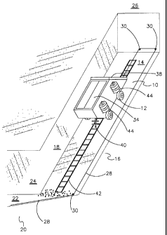
Figure 1 is, in cut-aMway perspective view, an inclined raise in which a raise
buggy
of the present invention is being conveyed.
Figure 2 is. in cut-a-way plan view, a tunnel and raise in which the raise
buggy of
the prc;semt invention is illustrated. for diagrammatic purposes.
simultaneously in both a lowered
position and an elevated position.
Figure 3 is the view of Figure 2 illustrating miners standing on an extended
drilling
platform 8.
6
CA 02214249 2005-07-29
Figure 4 is, in cut-a-way plan view., the raise buggy of the present invention
in
transport along the raise.
Figure 5 is, in a view looking upwards from underneath the forward end ofthe
raise
buggy of the present invention, the steering draw bar snagged against the
center line block at the
foot wa~(1 beneath the raise face.
Figure C~ is, in cut-a-way plan view, a draw bar, steering box and front wheel
and
axle components of the raise buggy of the present invention.
Figure 7 is, in side elevation view, the raise buggy of the present invention.
Figure 8 is, in plan view, the drilling platform of the raise buggy of the
pre,~sent
inventicon.
Figure 9 is, in partial cut-a-way view, the mounting arrangement of the
drilling
platform onto the front face of the raise buggy of the present invention.
Figure 10 is, in cut-a-way side elevation view, the drilling platform mounting
arm
of the raise buggy of the present invention.
Figure I l is, in partial cut-a-way perspective view, the front face of the
raise buggy
of the present invention with the drilling platform removed.
Figure I2 is, in partial cut-a-way plan view, an alternative embodiment of the
mounting arrangement of the drilling platform to the front face of the raise
buggy of the present
invention.
7
CA 02214249 2005-07-29
Figure l 3 is, in plan view, an altc,~t~tatir~e embodiment of the drilling
platform of the
raise buggy of the present invention.
Figure 14 is, in a perspective diagramatic view, the orientation of the drill
holes at
the raiso face.
Detailed Description of the Preferred Embodiments
As illustrated in Figure 1, raise buggy 10 has wheels 12 so that raise buggy
10 may
be elevated and lowered along inclined floor 14 ofraise 16. Raise 16 has
opposed side walls 18.
only onf: of which is illustrated in Figure 1 _, the other having been cut-
away for clarity. Raise 16
extends between tunnel 2() having tunnel floor 2? and tunnel side walls 24,
and rock face 2(i.
Raise buggy 10 is elevated and lowered along raise 16 by means of cable 28
running in blocks 3(>. Cable 28 may be tensioned so as to elevate raise buggy
10 along raise 16 or
may be cletensioned so as to lower raise buggy 10 along raise 16 by means of a
conventional logger
hoist 32, not shown in Figure 1 but seen in Figures ? and 3, which device is
known in the art.
Raise buggy 10 is provided with doors 34 which provide access to the interior
cavity o:f raise buggy 10 wherein may be stored tools, explosives or like
equipment and material.
whether in lock~,~rs or otherwise, required for drilling and blasting
«perations at rock face 2fi by
miners ?~6 standing on drilling platform 38.
Ratchet bar 40 is mounted, as by a hinge means, to the lower end of raise
buggy 10
so that ratchet bar 40 is free to drop down between the rungs of ladder 42 as
raise buggy 10 is
elevated along raise 16. Ratchetbar 40 dropping down between the rungs of
ladder 42 acts, in the
manner of a ratchet dog, to prevent raise buggy 10 from inadvertently rolling
backwards down
raise 16. As described above, ladder 42 is conventionally bolted as by rock
anchors to inclined
8
i
CA 02214249 2005-07-29
floor 14 and is extended clang inclined floor 14 as raise 16 is lengthened by
drilling and blasting
of rock ;face 2fi.
In one preferred embodiment, horizontally aligned wheels 44 or bumlxrs or the
like
are provided on both sides of raise buggy 10 to prevent raise buggy 1 U from
:jamming as it is being
raised or lowered in the event that raise buggy 10 does not remain centered on
a longitudinal
center line along raise 1 ft and contacts a side wall 18. In the preferred
embodiment, horizontal
wheels 44 are ratatably mounted about vertical axes as by vertically mounted
shafts.
In alternative embodiments, wheels 12, which are free to rotate about
generally
horizontal laterally ali~ed parallel axles in a conventional manner. may be
replaced by other
forms oi~ wheels or tracks so long as raise buggy 10 is free to rail along
inclined floor 14 without
the reef. for running an, or guidance by, tracks or rails.
In the preferred embodiment, the front pair of wheels 12, That is the pair of
wheels
12 at the: upper end of raise buggy 10 as raise buglry 10 is being elevated or
lowered along raise 1 G,
are pivotable in unison about a central vertical axis in the manner of
conventional draw bar
steering by means of draw bar 46 seen in Figure 4 and illustrated in better
detail in Figures S and ft.
Thus as seen in Figure 6, wheels t 2 are rotatably mounted on axle 48 and the
turning or pivoting
of wheels 12 about vertical axes may be controlled by draw bar 4G acting on
steering box 30.
As best seen in Figures 7 -13, drilling platform 38 may be selectively
inclinable so
as to provide a horizontal working surface. Drilling platform 38 may fold
outwardly to provide a
larger working area than that provided on the front face of raise buggy 10.
The primary work
surface 50 covering the front of raise buggy 10 may be supported on pivotally
mounted rigid
members such as I-beams 52. t-beams 52 rnay be pivotally mounted to raise
buggy 10 by means of
hinge bolts 54, laterally and generally horizontally aligned and secured in
place as best seen in
Figure 9~. Arms 5ti, which may be of steel or like rind material, and which
may have an array of
9
CA 02214249 2005-07-29
apertures therealong as seen in Figure 10, may be provided so that 1-beams 52
may be selectively
elevated or rotated relative to raise buggy 10. Arms 56 may be secured
relative to raise buggy 1 ()
by means of pins or rods a8 secured by cotter pins 60 and journalled through
the apertures in arms
S6 and c~arresponding aperture members 62 rigidly mounted to the front face
(i4 of raise buggy 1 U,
rigidly mounted by welding or the like.
In an alternative embodiment illustrated in Figure 12, I-beams 52 and primary
work
surface 5() may be selectively elevated and rotated relative to raise buggy 1
() by moans of hydraulic
actuators or jacks 66 instead of arms 56.
Primary work surface 5(), which advantageously is covered by screen mesh 68 to
provide a non-slip work surface, in. a preferred embodiment has folding work
surface extensions
70, mounted a_s by hinges 72 so as to be foldable outwardly from a storage
position laid flat over
primary work surface >0. Folding work surface extensions 70, once folded
outwardly from
primary work surface 5(), are adapted as by the use of hinges 7? and also by,
for example, chains
74, to provide planar extensions of primary work surface 50, co-planar with
primary work surface
5U.
Further advantageously, selectively extendable means for supporting lateral
scafFolding may be provided, and in a preferred embodiment, may simply be
selectively
extendable bolts or rods 76 slidingly supported within collars 78. C"ollaxs 78
may be; ri~,~idly
mounted to folding work surface extensions 70 so that, with folding work
surface extensions 70
folded outwardly from primary work surface 50, anti with bolts or rods 7(i
extended latera.ly
outward of folding work surface extensions 70, scaffolding 80, which may be
planks or the like,
may be laid over or otherwise mounted on to the portions of bolts or rods 76
extending laterally
outward of folding work surface extensions 70 and primary work surface 50.
Advantageously,
folding work surface extensions 7U anti scaffolding 8U is of an appropriate
sine so that, in
conjunction with primary work surface 50, drilling platform 38 extends
horizontally substantially
CA 02214249 2005-07-29
the entire widfh of raise lfi between side walls 18 and extends substantially
the entire distance
between inclined floor 14 and the ceiling of the raise. In this fashion, the
risk of a miner 3ti falling
ftom drillling platform 38 during drilling operations c>r the like, is
reduced. Because scaffolding 80
is easily removed or merely moved to one side, access is still provided to
doors 34 and. for
example. to water headers 82 and air headers 84 which., further
advantageously, may be mounted
to a side of raise buggy 10.
In c>ne preferred embodiment, primary work surface 50. which may be of
planking
or the lilke laid over 1-beams ~2, may have apertures 8~ therein, supporting
appropriately sized
pipes or pots, for storing therein stoppers, drill steel or like tools and
material required for drilling
and blasting operations. if the; apertures 8a in primary work surface s0 are
pipes or holes then
advantal;eously corresponding pots may be welded to the floor of the interior
cavity of raise buggy
for supporting the ends of, for example, drill steel passed through the
apertures 85 in primary
work su3~fac:e 50.
Ln a further preferred embodiment as illustrated in hi~,nzre 13, the tolding
work
surface extension 7() on the side of prirnarv work surface 50 closest to
incline floor 14, may have a
further <:mtwardly foldable flap 86, which may be rigid, or semi-rigid adapted
to lay flllsh against
inclined floor 14 so as to prevent inadvertently dropped equipment and
material falling down raise
16.
1n operation, it must be kept i.n mind that the design of the present
invention
provide:; a drilliang skip in the form of raise buggy 10 for linear driving of
raises when the raise is
inclined, for example, in excess of 30 degrees, to such a degree that
transport of tools and material
is difficult and hazardous typically requiring the use of ladder set in the
floor of the raise. In the
operation of the present invention, it is assumed that miners 36 at the face
of the raise; have means
for corn~nunicating, such as by way of radio, with a miner at the lowermost
end of the raise 16 or
in tunnel 20 whose ,job it is to operate the tugger hoist.
11
i
CA 02214249 2005-07-29
Advantageously, tugger hoist 32 should be of 5 horsepower or larger, although
the:
transport speed of raise buggy 10 will be slaw, approximating a gentle walking
speed., for example
or 2 miles per hour. Blocks 30 should be 6 inch heavy duty idler blocks
supported by 3/4 inch
heavy duty eye-baits. Cable 28 should advantageously be at least S/8 inch
steel core cable. Ladder
42 should be made of 1 inch type or steel advantageously in 8 foot len~,~ths.
Additionally. ladders
may be provided over doors 34 and along ratchet bar 40 to provide a miner easy
foothold for
climbing; onto raise buggy 10. Section.; of ladder 42 may be chained at their
top and bottom to
rock anchors so as to be in a straight line along the center line of raise 16,
and after each drilling
and blasting cycle, miners 36 should survey the center line of raise l fi
before raise buggy 1 () is
elevated up the raise.
As best sc;en in Figure 14, advantageously. four earner eye-bolt holes 9? may
be
drilled in rock face 26, one in each corner of rack face 26 and ono center-
line eye-bait hole 94 is
drilled i~z the foot wall {i.e. door 14) beneath rock face 2(i on the center
line 96 of inclined floor
14. If angle ac denotes the angle farmed between inclined floor 14 and the
horizontal {i.e. the
grade), then side lifter hales 98 and back holes 100 are also drilled so as to
foz~m the same angle «:
to the horizontal {although back hales 100 may conventionally be drilled at a
slightly larger angle
than an~;le ~x to the horizontal). In this fashion, the grade of inclined
floor 14 is kept constant as
raise 16 is extended. However, center-line lifter hale 102 should be drilled
approximately 3
degrees less {as denoted by angle (i) than the grade of inclined floor 14 to
ensure a good lift in the
rock during blasting, thereby forming a lip and making it easier to drill the
canter line eye-bolt hole
94 in. the foot wall 14 beneath rock face 26, to thereby align raise buglry I
0 with center line 96 so
that raise buggy 10 may be elevated and lowered without hitting side walls 18.
Unce drilling has been completed, and before blasting, when the: miners are
ready to
lower rfiise buggy 10, the miner at the top of the raise should hang a new
temporary ladder to stand
on and all loose chains should be secured. Safety chains lib, while raise
bug~~,ry 10 is in its elevated
1'
v i I i
CA 02214249 2005-07-29
position in raise 16. are secured between raise buggy 10 and side walls 18 so
as tc> prevent raise;
buggy 10 inadvertently slipping. Also while raise buggry 10 is in its elevated
position in raise 16.
the tuggc;r hoist should be secured by, for example, a brake with chain and
loch. including turning
of and securing the air supply to the tugger hoist to avoid inadvertent
triggering of the hoist.
For lowering raise buggy 10, safety chains 8b are released and ratchet bar 40
raised
so that cable 28 may be detensioned allowing raise buggy 10 to roll backwards
down raise 16.
Safi;ty chains H8 may be secured to side walls 18 by J-bolts 90.
Advantageously. in the case ofblasting 8 foot rounds. it is important to
elevate raise
buggy 1 () as far up as possible so as to snug as closely possible to block 30
on the center line of
raise 1 (i. In a preferred embodiment, drilling platform 38 extends forw~u-dly
of raise buggy 10 so
as to extend over drawbar 46 and over centre-line block 30 when drawbar 4(> is
snuggc;d against
centre-line block 3(). The extent that drilling platform 38 extends forwardly
of raise bugging 10,
and the corresponding length of drawbar 46 should be sufficient so that when
the forward edge of
drilling 1>latfe~rm 38 is brought into proximity with the footwa.ll, that is,
with inclined filoor 14. at
the copper end of the raise adjacent the raise face 26, that a sufficient
distance is left between
drilling platform 38 and raise face 26 for the miners to hold therebetwcen
their drills and related
equipment, which, to be consistent with this disclosure, would be a distance
of 8 feet.
As raise bug~,ry 10 is being lowered following a raise round, once th.e raise
round
has been drilled, loaded and ready to blast, then: one of the miners descends
the raise to tugger
hoist 32 in tunnel 20. the miner left at the top of the raise 1 (i dismantles
all safety chains and all
safety dogs such as ratchet bar 40 and stands clear on a newly installed
temporary ladder and
passes instructions down to the miner at tugger hoist 22, the miner at the
tugger hoist lowers raise
buggy 1 C~ on cables 28, the miner still at the upper end of the raise I 6
removes the center block 30
<3nd hanks it with the adjacent block 30 on side wall 18, and cables 28 are
hung on J-bolts
1
n i I i
CA 02214249 2005-07-29
previously installed at earlier raise faces as the miner descends the raise to
prevent cable damage
during blasting.
If, as an example, raise 1 fi has to be driven 200 feet, then the length of
cable 28 on
the dr~un of tugger hoist 32 should advantageously be 500 feet of non-spliced
cable. Drilling
platfc~rm~ 38. may be used, as raised buggy 10 is elevated in raise 1 fi, to
carry large eduipment to
each level for example Blushers and fans.
In order to remove raise bu~~y 10 from raise 16 prior to blasting,
advantageously
raise bu;gy 1() is pulled into tunnel 20. This may be accomplished. for
example, by extracting
slack calzle from tugger hoist 3? and attaching the cable to a hook or the
like provided at the rear
of raise ibuggy l 0 for that purpose and then tightening the cable so as tc~
pull raise buggy 10 into
tunnel 20 cover the intersection between raise 16 and htnnel 20 which,
advantageously, will be a
short ramp formed from previous blast rock left for that purpose. Raise buggy
10 should be pulled
into tunnel 20 a sufficient distance to allow the blast rock to be removed
from the bottom of raise
1(i following blasting.
As will be apparent to those skilled in the art in the light of the foregoing
disclosure, many alterations and modifications are possible in the practice of
this invention
without departing from the spirit or scope thereof. Accordingly, the scope of
the invention is to be
construed in accordance with the substance defined by the following claims.
14