Language selection

Search

Patent 2214370 Summary

Third-party information liability

Some of the information on this Web page has been provided by external sources. The Government of Canada is not responsible for the accuracy, reliability or currency of the information supplied by external sources. Users wishing to rely upon this information should consult directly with the source of the information. Content provided by external sources is not subject to official languages, privacy and accessibility requirements.

Claims and Abstract availability

Any discrepancies in the text and image of the Claims and Abstract are due to differing posting times. Text of the Claims and Abstract are posted:

  • At the time the application is open to public inspection;
  • At the time of issue of the patent (grant).
(12) Patent Application: (11) CA 2214370
(54) English Title: METHOD AND APPARATUS FOR COUPLING POWER GENERATOR TO UTILITY POWER GRID
(54) French Title: METHODE ET CIRCUIT POUR COUPLER UNE GENERATRICE DE COURANT AU SECTEUR
Status: Deemed Abandoned and Beyond the Period of Reinstatement - Pending Response to Notice of Disregarded Communication
Bibliographic Data
(51) International Patent Classification (IPC):
  • H01H 07/16 (2006.01)
  • H02J 03/40 (2006.01)
(72) Inventors :
  • DOSANI, NAZIR (Canada)
  • LADHA, NIZAR (Canada)
(73) Owners :
  • NAZIR DOSANI
  • NIZAR LADHA
(71) Applicants :
  • NAZIR DOSANI (Canada)
  • NIZAR LADHA (Canada)
(74) Agent:
(74) Associate agent:
(45) Issued:
(22) Filed Date: 1997-10-28
(41) Open to Public Inspection: 1999-04-28
Availability of licence: N/A
Dedicated to the Public: N/A
(25) Language of filing: English

Patent Cooperation Treaty (PCT): No

(30) Application Priority Data: None

Abstracts

English Abstract


A switching circuit to reduce flashing in a switching circuit, when coupling a
power generator to utility power grid. The reduction, in flash, is achieved by
monitoring AC sine waves of utility power grid and power generator for
compatibility in frequency, amplitude and phase. The switching occurs when
all monitored signals are, momentarily, equal in time.


Claims

Note: Claims are shown in the official language in which they were submitted.

THE EMBODIMENTS OF THE INVENTION IN WHICH AN
EXCLUSIVE PROPERTY OR PRIVILEGE IS CLAIMED ARE
DEFINED AS FOLLOWS:
1. A switching means for stabilized coupling of an induction generator to an
alternating current (AC) utility power grid, comprising:
monitoring frequency, amplitude and phase of utility power grid,
monitoring frequency, amplitude and phase of induction generator, and
hybrid switching means for coupling induction generator to utility
power grid when the monitored frequency, amplitude and phase are
equal in time between the induction generator and utility power grid.
2. A switching means as claimed in claim 1, wherein the hybrid switching
means comprises a solid state relay in series with a mechanical relay.
3. A switching means as claimed in claim 2, comprising delay means for
delaying the closing of solid state relay relative to closing of mechanical
relay.
4. A switching means as claimed in claim 2, comprising delay means for
delaying the opening of mechanical relay relative to opening of solid state
relay.

Description

Note: Descriptions are shown in the official language in which they were submitted.


CA 02214370 1997-10-28
Field of Invention
This invention relates to a switching circuit suitable for power generators and
particularly to an ~llxili~ry generating system for coupling an induction motor
type generator to an AC power line for ~d(lin3~ power to that line.
Back~round of the Invention
Various methods have been proposed, to couple a power generator and in
particular, windmill generated power using an induction type motor, to a
0 utility power grid.
Mechanical relays, used to couple high culrellls, have a limited operating life
due to excessive wear caused by fl~shing between the relay contacts when
they make or break.
Wind velocity is random, unpredictable and subject to rapid changes and
therefor complicates the controller in which the generator is connected to
utility power grid.
2 o The problem is further complicated, by the fact that utility power grid is not
stable either. In North America, the amplitude changes by as much as 7% and
the frequency by 0.5Hz, while in other parts of the world the changes are a lot
higher.
25 Naran Kanti (Patent number PCT WO 95/19659) teaches us a method of

CA 02214370 1997-10-28
using a solid state relay and a mechanical relay in parallel to reduce heat
within the solid state relay.
Frank J. Bourbeau ~'atent number US 4,656,413) teaches us a method of
5 using SCR, two per phase, to couple a power generator to a utility grid. The
algolilhlll used is complex and not suitable for unstable utility power grid.
Frank J. Nola ~atent number US 4,473,792) teaches us a method of
controlling a triac to connect the generator to utility power grid. The triac is10 turned on at a relatively late point in each half cycle to reduce power supplied
by the utility power grid to the induction motor type generator and the net
power delivered to the line is increased. This method does not monitor the
changes in the power grid before connecting the generator to the power grid.
Summary of the Invention
There remains a need to couple a power generator to utility power grid which
is not stable (frequency and amplitude), as seen in non-industrialized
countries to elimin~te in-rush cullell~ and fl~hing
It is the object of this invention to effectively reduce fl~.~hing when couplingto utility power grid by monitoring AC sine waves of utility power grid and
power generator, for compatibility in frequency, amplitude and phase.
2 5 Another object of this invention is to isolate the generator from the utility

CA 02214370 1997-10-28
power grid when generator is de-coupled.
A further object of this invention is to effectively reduce in-rush current whena generator, which has induction type motor, is coupled to utility grid.
Brief Description of the Dr~.will~s
In drawings which illustrate by way of example only a preferred embodiment
of the present invention,
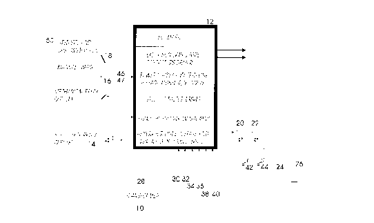
Figure 1 is a block diagram of one embodiment of the present invention
showing connection between utility power grid and windmill power
generator;
5 Figure 2A is illustrating the frequency and ~mplitude of power utility grid;
and
Figure 2B is illustrating the frequency and amplitude of generator.
Detailed Descrintion of the Invention
As shown in Figure 1, in one embodiment the present invention comprises an
AC induction motor/generator 24 which is mechanically driven by propeller
26 of a win~lmill (not shown).

CA 02214370 1997-10-28
Capacitors 42 and 44, are excitation or power factor correction capacitors,
which are brought on line by solid state relays 20 & 22 under the control of
controller 12.
Voltage sensors 30, 34 and 38 sense the voltage output of the generators
while sensors 32, 36 and 40 sense the cullelll ofthe generator.
Transformer 28 converts three phase output of generator 24 into a single
phase for connection to utility power grid 50 through solid state relay 14,
0 mechanical relay 16 and manual disconnect switch 18 which is required for
maintenance purposes.
Although, three phase output of the generator can be connected to the utility
power grid, for simplicity, only a single phase connection is shown in the
example.
In the initial state, all relays 14, 16, 20 and 22 are opened to isolate all
sections from each other and from power utility grid 50.
20 Wind velocity will start to turn propeller 26 which in turn, drives the
induction motor 24. The output of generator 24 is monitored by controller 12
via sensors 30 to 40 for frequency, amplitude and phase.
The presence of frequency and amplitude at sensors 30 to 40, indicates that
there is enough wind velocity to start the generator, in which case, capacitors

CA 02214370 1997-10-28
42 and 44 are brought on-line to start the excitation process.
At a pre-programmed generator output value, mechanical relay 16 is brought
on-line while solid state relay 14 is still left open.
At this time, controller 12 starts to monitor utility power grid via sensors 46
and 48 and power generator via sensors 30 to 40 for compatibility in
frequency, amplitude and phase.
0 The acceleration of generator 24 is also monitored, via the frequency of the
output, to predict the time when the frequency output of the generator 24 will
equal the utility power grid 50.
Solid state relay 14 is enabled at zero-crossing, when all monitored signals
(frequency, amplitude and phase) between utility power grid 50 and power
generator 24 are momentarily equal in time.
As the connection between utility power grid 50 and generator 24 is made
only when both frequency and amplitude are equal, the variations in
20 frequency and amplitude within the utility power grid 50 and generator 24 are taken into account before connection is made.
As the speed of solid state relay is extremely fast, in the order of micro
seconds, the connection between utility power grid 50 and generator 24 is
25 made while frequency and amplitude are still equal and thus effectually

CA 02214370 1997-10-28
reducing flash and in-rush cull~nl problems.
Current sensors 32, 36, 40 and 48 are mollilored by controller 12 during
operation, for flow of power. The flow of power lis from utility power grid 50
to generator 24 (generator acting as a motor) when the wind velocity is low
and from the generator 24 to utility power grid 50 when there is sufficient
wind velocity.
Generator 24 is disconnected from utility power grid 50, when the wind
10 velocity is low for a pre-programmed period of time or when the power
re~-lin~ from sensors 30 to 40 are out of sync with each other indicating a
problem or unbalancing of phases within generator 24.
Over heating of generator 24 (sensor not shown) will also disconnect the
generator 24 from utility power grid 50.
During disconnect phase, the solid state relay 14 is turned off first and then
mechanical relay 16 is disabled to isolate generator 24 from utility power grid
50.
Figure 2A shows the waveform of utility power grid 50 and Figure 2B shows
the output of generator 24 at start up. As shown in Figure 2A, the utility
power grid 50 is stable for the period of time, while the output of generator
24, as shown in Figure 2B, is ch~n~ing.

CA 02214370 1997-10-28
As indicated in Figure 2A and 2B, solid state relay 14 is enabled at zero-
crossing 52, when all monitored signals (frequency, amplitude and phase)
between utility power grid 50 and power generator 24 are momentarily equal
m time.
A prerelled embodiment of the invention having thus been described by way
of example only, it will be apparent to those skilled in the art that
modifications and adaptations may be made without departing from the scope
of invention, as set out in the appended claims.

Representative Drawing
A single figure which represents the drawing illustrating the invention.
Administrative Status

2024-08-01:As part of the Next Generation Patents (NGP) transition, the Canadian Patents Database (CPD) now contains a more detailed Event History, which replicates the Event Log of our new back-office solution.

Please note that "Inactive:" events refers to events no longer in use in our new back-office solution.

For a clearer understanding of the status of the application/patent presented on this page, the site Disclaimer , as well as the definitions for Patent , Event History , Maintenance Fee  and Payment History  should be consulted.

Event History

Description Date
Inactive: IPC from MCD 2006-03-12
Application Not Reinstated by Deadline 2003-10-28
Time Limit for Reversal Expired 2003-10-28
Inactive: Adhoc Request Documented 2003-07-31
Deemed Abandoned - Failure to Respond to Maintenance Fee Notice 2002-10-28
Inactive: Abandon-RFE+Late fee unpaid-Correspondence sent 2002-10-28
Letter Sent 2001-11-06
Inactive: Delete abandonment 2001-02-13
Deemed Abandoned - Failure to Respond to Maintenance Fee Notice 2000-10-30
Inactive: Cover page published 1999-06-02
Application Published (Open to Public Inspection) 1999-04-28
Inactive: IPC assigned 1997-12-10
Classification Modified 1997-12-10
Inactive: First IPC assigned 1997-12-10
Inactive: Filing certificate - No RFE (English) 1997-11-05
Inactive: Office letter 1997-11-05
Application Received - Regular National 1997-11-04

Abandonment History

Abandonment Date Reason Reinstatement Date
2002-10-28
2000-10-30

Maintenance Fee

The last payment was received on 2001-10-19

Note : If the full payment has not been received on or before the date indicated, a further fee may be required which may be one of the following

  • the reinstatement fee;
  • the late payment fee; or
  • additional fee to reverse deemed expiry.

Patent fees are adjusted on the 1st of January every year. The amounts above are the current amounts if received by December 31 of the current year.
Please refer to the CIPO Patent Fees web page to see all current fee amounts.

Fee History

Fee Type Anniversary Year Due Date Paid Date
Application fee - small 1997-10-28
MF (application, 2nd anniv.) - small 02 1999-10-28 1999-10-27
MF (application, 3rd anniv.) - small 03 2000-10-30 2000-10-15
MF (application, 4th anniv.) - small 04 2001-10-29 2001-10-19
Owners on Record

Note: Records showing the ownership history in alphabetical order.

Current Owners on Record
NAZIR DOSANI
NIZAR LADHA
Past Owners on Record
None
Past Owners that do not appear in the "Owners on Record" listing will appear in other documentation within the application.
Documents

To view selected files, please enter reCAPTCHA code :


To view images, click a link in the Document Description column. To download the documents, select one or more checkboxes in the first column and then click the "Download Selected in PDF format (Zip Archive)" or the "Download Selected as Single PDF" button.

List of published and non-published patent-specific documents on the CPD .

If you have any difficulty accessing content, you can call the Client Service Centre at 1-866-997-1936 or send them an e-mail at CIPO Client Service Centre.


Document
Description 
Date
(yyyy-mm-dd) 
Number of pages   Size of Image (KB) 
Representative drawing 1999-06-01 1 12
Abstract 1997-10-27 1 11
Description 1997-10-27 7 200
Claims 1997-10-27 1 30
Drawings 1997-10-27 2 37
Filing Certificate (English) 1997-11-04 1 164
Notice: Maintenance Fee Reminder 1999-07-28 1 130
Notice: Maintenance Fee Reminder 2000-07-30 1 118
Notice: Maintenance Fee Reminder 2001-07-30 1 120
Reminder - Request for Examination 2002-07-01 1 127
Notice: Maintenance Fee Reminder 2002-07-29 1 130
Courtesy - Abandonment Letter (Request for Examination) 2003-01-05 1 167
Courtesy - Abandonment Letter (Maintenance Fee) 2002-11-24 1 176
Second Notice: Maintenance Fee Reminder 2003-04-28 1 114
Notice: Maintenance Fee Reminder 2003-07-28 1 115
Correspondence 1997-11-04 1 17
Correspondence 2000-10-30 2 74
Correspondence 2001-11-05 2 95
Fees 1999-10-26 1 70
Fees 2001-10-18 1 71