Sélection de la langue

Search

Sommaire du brevet 2214370 

Énoncé de désistement de responsabilité concernant l'information provenant de tiers

Une partie des informations de ce site Web a été fournie par des sources externes. Le gouvernement du Canada n'assume aucune responsabilité concernant la précision, l'actualité ou la fiabilité des informations fournies par les sources externes. Les utilisateurs qui désirent employer cette information devraient consulter directement la source des informations. Le contenu fourni par les sources externes n'est pas assujetti aux exigences sur les langues officielles, la protection des renseignements personnels et l'accessibilité.

Disponibilité de l'Abrégé et des Revendications

L'apparition de différences dans le texte et l'image des Revendications et de l'Abrégé dépend du moment auquel le document est publié. Les textes des Revendications et de l'Abrégé sont affichés :

  • lorsque la demande peut être examinée par le public;
  • lorsque le brevet est émis (délivrance).
(12) Demande de brevet: (11) CA 2214370
(54) Titre français: METHODE ET CIRCUIT POUR COUPLER UNE GENERATRICE DE COURANT AU SECTEUR
(54) Titre anglais: METHOD AND APPARATUS FOR COUPLING POWER GENERATOR TO UTILITY POWER GRID
Statut: Réputée abandonnée et au-delà du délai pour le rétablissement - en attente de la réponse à l’avis de communication rejetée
Données bibliographiques
Abrégés

Abrégé anglais


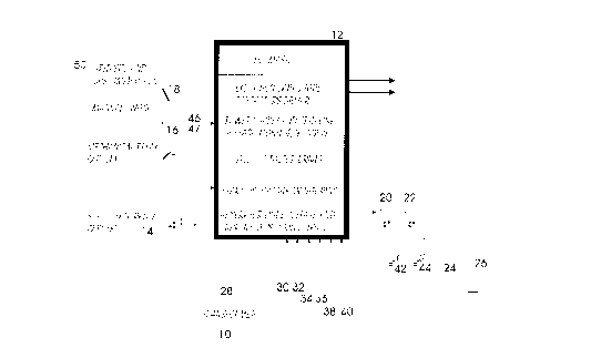
A switching circuit to reduce flashing in a switching circuit, when coupling a
power generator to utility power grid. The reduction, in flash, is achieved by
monitoring AC sine waves of utility power grid and power generator for
compatibility in frequency, amplitude and phase. The switching occurs when
all monitored signals are, momentarily, equal in time.

Revendications

Note : Les revendications sont présentées dans la langue officielle dans laquelle elles ont été soumises.


THE EMBODIMENTS OF THE INVENTION IN WHICH AN
EXCLUSIVE PROPERTY OR PRIVILEGE IS CLAIMED ARE
DEFINED AS FOLLOWS:
1. A switching means for stabilized coupling of an induction generator to an
alternating current (AC) utility power grid, comprising:
monitoring frequency, amplitude and phase of utility power grid,
monitoring frequency, amplitude and phase of induction generator, and
hybrid switching means for coupling induction generator to utility
power grid when the monitored frequency, amplitude and phase are
equal in time between the induction generator and utility power grid.
2. A switching means as claimed in claim 1, wherein the hybrid switching
means comprises a solid state relay in series with a mechanical relay.
3. A switching means as claimed in claim 2, comprising delay means for
delaying the closing of solid state relay relative to closing of mechanical
relay.
4. A switching means as claimed in claim 2, comprising delay means for
delaying the opening of mechanical relay relative to opening of solid state
relay.

Description

Note : Les descriptions sont présentées dans la langue officielle dans laquelle elles ont été soumises.


CA 02214370 1997-10-28
Field of Invention
This invention relates to a switching circuit suitable for power generators and
particularly to an ~llxili~ry generating system for coupling an induction motor
type generator to an AC power line for ~d(lin3~ power to that line.
Back~round of the Invention
Various methods have been proposed, to couple a power generator and in
particular, windmill generated power using an induction type motor, to a
0 utility power grid.
Mechanical relays, used to couple high culrellls, have a limited operating life
due to excessive wear caused by fl~shing between the relay contacts when
they make or break.
Wind velocity is random, unpredictable and subject to rapid changes and
therefor complicates the controller in which the generator is connected to
utility power grid.
2 o The problem is further complicated, by the fact that utility power grid is not
stable either. In North America, the amplitude changes by as much as 7% and
the frequency by 0.5Hz, while in other parts of the world the changes are a lot
higher.
25 Naran Kanti (Patent number PCT WO 95/19659) teaches us a method of

CA 02214370 1997-10-28
using a solid state relay and a mechanical relay in parallel to reduce heat
within the solid state relay.
Frank J. Bourbeau ~'atent number US 4,656,413) teaches us a method of
5 using SCR, two per phase, to couple a power generator to a utility grid. The
algolilhlll used is complex and not suitable for unstable utility power grid.
Frank J. Nola ~atent number US 4,473,792) teaches us a method of
controlling a triac to connect the generator to utility power grid. The triac is10 turned on at a relatively late point in each half cycle to reduce power supplied
by the utility power grid to the induction motor type generator and the net
power delivered to the line is increased. This method does not monitor the
changes in the power grid before connecting the generator to the power grid.
Summary of the Invention
There remains a need to couple a power generator to utility power grid which
is not stable (frequency and amplitude), as seen in non-industrialized
countries to elimin~te in-rush cullell~ and fl~hing
It is the object of this invention to effectively reduce fl~.~hing when couplingto utility power grid by monitoring AC sine waves of utility power grid and
power generator, for compatibility in frequency, amplitude and phase.
2 5 Another object of this invention is to isolate the generator from the utility

CA 02214370 1997-10-28
power grid when generator is de-coupled.
A further object of this invention is to effectively reduce in-rush current whena generator, which has induction type motor, is coupled to utility grid.
Brief Description of the Dr~.will~s
In drawings which illustrate by way of example only a preferred embodiment
of the present invention,
Figure 1 is a block diagram of one embodiment of the present invention
showing connection between utility power grid and windmill power
generator;
5 Figure 2A is illustrating the frequency and ~mplitude of power utility grid;
and
Figure 2B is illustrating the frequency and amplitude of generator.
Detailed Descrintion of the Invention
As shown in Figure 1, in one embodiment the present invention comprises an
AC induction motor/generator 24 which is mechanically driven by propeller
26 of a win~lmill (not shown).

CA 02214370 1997-10-28
Capacitors 42 and 44, are excitation or power factor correction capacitors,
which are brought on line by solid state relays 20 & 22 under the control of
controller 12.
Voltage sensors 30, 34 and 38 sense the voltage output of the generators
while sensors 32, 36 and 40 sense the cullelll ofthe generator.
Transformer 28 converts three phase output of generator 24 into a single
phase for connection to utility power grid 50 through solid state relay 14,
0 mechanical relay 16 and manual disconnect switch 18 which is required for
maintenance purposes.
Although, three phase output of the generator can be connected to the utility
power grid, for simplicity, only a single phase connection is shown in the
example.
In the initial state, all relays 14, 16, 20 and 22 are opened to isolate all
sections from each other and from power utility grid 50.
20 Wind velocity will start to turn propeller 26 which in turn, drives the
induction motor 24. The output of generator 24 is monitored by controller 12
via sensors 30 to 40 for frequency, amplitude and phase.
The presence of frequency and amplitude at sensors 30 to 40, indicates that
there is enough wind velocity to start the generator, in which case, capacitors

CA 02214370 1997-10-28
42 and 44 are brought on-line to start the excitation process.
At a pre-programmed generator output value, mechanical relay 16 is brought
on-line while solid state relay 14 is still left open.
At this time, controller 12 starts to monitor utility power grid via sensors 46
and 48 and power generator via sensors 30 to 40 for compatibility in
frequency, amplitude and phase.
0 The acceleration of generator 24 is also monitored, via the frequency of the
output, to predict the time when the frequency output of the generator 24 will
equal the utility power grid 50.
Solid state relay 14 is enabled at zero-crossing, when all monitored signals
(frequency, amplitude and phase) between utility power grid 50 and power
generator 24 are momentarily equal in time.
As the connection between utility power grid 50 and generator 24 is made
only when both frequency and amplitude are equal, the variations in
20 frequency and amplitude within the utility power grid 50 and generator 24 are taken into account before connection is made.
As the speed of solid state relay is extremely fast, in the order of micro
seconds, the connection between utility power grid 50 and generator 24 is
25 made while frequency and amplitude are still equal and thus effectually

CA 02214370 1997-10-28
reducing flash and in-rush cull~nl problems.
Current sensors 32, 36, 40 and 48 are mollilored by controller 12 during
operation, for flow of power. The flow of power lis from utility power grid 50
to generator 24 (generator acting as a motor) when the wind velocity is low
and from the generator 24 to utility power grid 50 when there is sufficient
wind velocity.
Generator 24 is disconnected from utility power grid 50, when the wind
10 velocity is low for a pre-programmed period of time or when the power
re~-lin~ from sensors 30 to 40 are out of sync with each other indicating a
problem or unbalancing of phases within generator 24.
Over heating of generator 24 (sensor not shown) will also disconnect the
generator 24 from utility power grid 50.
During disconnect phase, the solid state relay 14 is turned off first and then
mechanical relay 16 is disabled to isolate generator 24 from utility power grid
50.
Figure 2A shows the waveform of utility power grid 50 and Figure 2B shows
the output of generator 24 at start up. As shown in Figure 2A, the utility
power grid 50 is stable for the period of time, while the output of generator
24, as shown in Figure 2B, is ch~n~ing.

CA 02214370 1997-10-28
As indicated in Figure 2A and 2B, solid state relay 14 is enabled at zero-
crossing 52, when all monitored signals (frequency, amplitude and phase)
between utility power grid 50 and power generator 24 are momentarily equal
m time.
A prerelled embodiment of the invention having thus been described by way
of example only, it will be apparent to those skilled in the art that
modifications and adaptations may be made without departing from the scope
of invention, as set out in the appended claims.

Dessin représentatif
Une figure unique qui représente un dessin illustrant l'invention.
États administratifs

2024-08-01 : Dans le cadre de la transition vers les Brevets de nouvelle génération (BNG), la base de données sur les brevets canadiens (BDBC) contient désormais un Historique d'événement plus détaillé, qui reproduit le Journal des événements de notre nouvelle solution interne.

Veuillez noter que les événements débutant par « Inactive : » se réfèrent à des événements qui ne sont plus utilisés dans notre nouvelle solution interne.

Pour une meilleure compréhension de l'état de la demande ou brevet qui figure sur cette page, la rubrique Mise en garde , et les descriptions de Brevet , Historique d'événement , Taxes périodiques et Historique des paiements devraient être consultées.

Historique d'événement

Description Date
Inactive : CIB de MCD 2006-03-12
Demande non rétablie avant l'échéance 2003-10-28
Le délai pour l'annulation est expiré 2003-10-28
Inactive : Demande ad hoc documentée 2003-07-31
Réputée abandonnée - omission de répondre à un avis sur les taxes pour le maintien en état 2002-10-28
Inactive : Abandon.-RE+surtaxe impayées-Corr envoyée 2002-10-28
Lettre envoyée 2001-11-06
Inactive : Supprimer l'abandon 2001-02-13
Réputée abandonnée - omission de répondre à un avis sur les taxes pour le maintien en état 2000-10-30
Inactive : Page couverture publiée 1999-06-02
Demande publiée (accessible au public) 1999-04-28
Inactive : CIB attribuée 1997-12-10
Symbole de classement modifié 1997-12-10
Inactive : CIB en 1re position 1997-12-10
Inactive : Certificat de dépôt - Sans RE (Anglais) 1997-11-05
Inactive : Lettre officielle 1997-11-05
Demande reçue - nationale ordinaire 1997-11-04

Historique d'abandonnement

Date d'abandonnement Raison Date de rétablissement
2002-10-28
2000-10-30

Taxes périodiques

Le dernier paiement a été reçu le 2001-10-19

Avis : Si le paiement en totalité n'a pas été reçu au plus tard à la date indiquée, une taxe supplémentaire peut être imposée, soit une des taxes suivantes :

  • taxe de rétablissement ;
  • taxe pour paiement en souffrance ; ou
  • taxe additionnelle pour le renversement d'une péremption réputée.

Les taxes sur les brevets sont ajustées au 1er janvier de chaque année. Les montants ci-dessus sont les montants actuels s'ils sont reçus au plus tard le 31 décembre de l'année en cours.
Veuillez vous référer à la page web des taxes sur les brevets de l'OPIC pour voir tous les montants actuels des taxes.

Historique des taxes

Type de taxes Anniversaire Échéance Date payée
Taxe pour le dépôt - petite 1997-10-28
TM (demande, 2e anniv.) - petite 02 1999-10-28 1999-10-27
TM (demande, 3e anniv.) - petite 03 2000-10-30 2000-10-15
TM (demande, 4e anniv.) - petite 04 2001-10-29 2001-10-19
Titulaires au dossier

Les titulaires actuels et antérieures au dossier sont affichés en ordre alphabétique.

Titulaires actuels au dossier
NAZIR DOSANI
NIZAR LADHA
Titulaires antérieures au dossier
S.O.
Les propriétaires antérieurs qui ne figurent pas dans la liste des « Propriétaires au dossier » apparaîtront dans d'autres documents au dossier.
Documents

Pour visionner les fichiers sélectionnés, entrer le code reCAPTCHA :


Pour visualiser une image, cliquer sur un lien dans la colonne description du document. Pour télécharger l'image (les images), cliquer l'une ou plusieurs cases à cocher dans la première colonne et ensuite cliquer sur le bouton "Télécharger sélection en format PDF (archive Zip)" ou le bouton "Télécharger sélection (en un fichier PDF fusionné)".

Liste des documents de brevet publiés et non publiés sur la BDBC .

Si vous avez des difficultés à accéder au contenu, veuillez communiquer avec le Centre de services à la clientèle au 1-866-997-1936, ou envoyer un courriel au Centre de service à la clientèle de l'OPIC.


Description du
Document 
Date
(aaaa-mm-jj) 
Nombre de pages   Taille de l'image (Ko) 
Dessin représentatif 1999-06-01 1 12
Abrégé 1997-10-27 1 11
Description 1997-10-27 7 200
Revendications 1997-10-27 1 30
Dessins 1997-10-27 2 37
Certificat de dépôt (anglais) 1997-11-04 1 164
Avis de rappel: Taxes de maintien 1999-07-28 1 130
Avis de rappel: Taxes de maintien 2000-07-30 1 118
Avis de rappel: Taxes de maintien 2001-07-30 1 120
Rappel - requête d'examen 2002-07-01 1 127
Avis de rappel: Taxes de maintien 2002-07-29 1 130
Courtoisie - Lettre d'abandon (requête d'examen) 2003-01-05 1 167
Courtoisie - Lettre d'abandon (taxe de maintien en état) 2002-11-24 1 176
Deuxième avis de rappel: taxes de maintien 2003-04-28 1 114
Avis de rappel: Taxes de maintien 2003-07-28 1 115
Correspondance 1997-11-04 1 17
Correspondance 2000-10-30 2 74
Correspondance 2001-11-05 2 95
Taxes 1999-10-26 1 70
Taxes 2001-10-18 1 71