Language selection

Search

Patent 2214621 Summary

Third-party information liability

Some of the information on this Web page has been provided by external sources. The Government of Canada is not responsible for the accuracy, reliability or currency of the information supplied by external sources. Users wishing to rely upon this information should consult directly with the source of the information. Content provided by external sources is not subject to official languages, privacy and accessibility requirements.

Claims and Abstract availability

Any discrepancies in the text and image of the Claims and Abstract are due to differing posting times. Text of the Claims and Abstract are posted:

  • At the time the application is open to public inspection;
  • At the time of issue of the patent (grant).
(12) Patent: (11) CA 2214621
(54) English Title: SNOW REMOVAL DEVICE
(54) French Title: APPAREIL DE DENEIGEMENT
Status: Deemed expired
Bibliographic Data
(51) International Patent Classification (IPC):
  • E01H 5/07 (2006.01)
  • B62B 1/14 (2006.01)
  • E01C 19/20 (2006.01)
  • E01H 5/02 (2006.01)
(72) Inventors :
  • SINCLAIR, SYLVESTER JR. (United States of America)
(73) Owners :
  • SINCLAIR, SYLVESTER JR. (United States of America)
(71) Applicants :
  • SINCLAIR, SYLVESTER JR. (United States of America)
(74) Agent: OSLER, HOSKIN & HARCOURT LLP
(74) Associate agent:
(45) Issued: 2000-12-26
(22) Filed Date: 1997-09-04
(41) Open to Public Inspection: 1998-03-05
Examination requested: 1997-09-04
Availability of licence: N/A
(25) Language of filing: English

Patent Cooperation Treaty (PCT): No

(30) Application Priority Data:
Application No. Country/Territory Date
08/708,714 United States of America 1996-09-05

Abstracts

English Abstract


A snow removal push board and snow barrow. More
specifically, the invention is a snow push board made
up of a generally rectangular board with handles on
one side and a scraping edge directly opposite the
handles. The push board is operated by grasping the
handles in front of the waist and allowing the board
to be on an approximately forty-five degree incline
from the user's waist to the ground while pushing the
scraping edge along the ground. The snow barrow
includes a board having a scraping edge and generally
triangular sides. The snow barrow has handles for the
user to grasp and push the barrow with two large
wheels in the rear and two smaller wheels in the front
of the barrow for maneuvering. The snow barrow also
has structure for dispensing salt using either a
vertical pinwheel or track dispersement axles in
between the rear wheels of the barrow. The amount of
salt dispensed can be controlled by adjusting a gauge.


French Abstract

Planche à grattoir servant au déneigement et brouette à neige. La planche est habituellement rectangulaire et comporte des poignées sur un côté et un grattoir directement sur le côté opposé des poignées. Pour se servir de la planche, l'utilisateur doit prendre les poignées devant lui à la hauteur de sa taille et maintenir la planche à grattoir à un angle d'environ quarante-cinq degrés par rapport au sol, et la pousser sur le sol. La brouette à neige comporte une planche à grattoir et des côtés habituellement triangulaires ainsi que des poignées que peut prendre l'utilisateur pour pousser la brouette. Celle-ci est munie de deux grosses roues arrière et de deux petites roues avant permettant de la manoeuvrer. La brouette à neige est aussi équipée d'une structure pour épandre du sel, soit au moyen d'une roue verticale, soit de rails situés entre les roues arrière de la brouette. La quantité de sel épandue peut être réglée au moyen d'un appareil de mesure.

Claims

Note: Claims are shown in the official language in which they were submitted.


THE EMBODIMENTS OF THE INVENTION IN WHICH AN EXCLUSIVE
PROPERTY OR PRIVILEGE IS CLAIMED ARE DEFINED AS FOLLOWS:

1. A snow removal device comprising:
a barrow of substantially uniform construction having a
rear wall and a pair of upwardly sloping sides defining a pair
of rear wheel wells, said barrow including:
a front snow scooping compartment including a bottom
with a leading edge;
a rear salt storage and dispensing compartment
including a bottom having a fixed portion and a
spring-actuated door swingably mounted to said fixed
portion which allows for the dispensing of salt; and
a partition separating said snow scooping
compartment and said salt storage and dispensing
compartment;
a pair of rear wheels housed within said pair of
rear wheel wells, said pair of wheels joined
together by a rear dispersement axle.

2. The snow removal device of claim 1, further comprising
a pair of front wheels located under said snow scooping
compartment.

3. The snow removal device of claim 1 or 2, wherein said
dispersement axle is a track dispersement axle for receiving
and dispensing salt.

4. The snow removal device of any one of claims 1 to 3,
further comprising a gauge which is mechanically attached to
said door for adjusting the opening of said door and the amount
of salt dispensed.

5. The snow removal device of any one of claims 1 to 4,
further comprising a wall sloping from said partition to said


bottom of said salt storage dispensing compartments, such that
salt will be funneled to said door.

6. The snow removal device of any one of claims 1 to 5,
wherein said rear wall of said barrow includes handles.

7. The snow removal device of any one of claims 1 to 6,
in combination with a receptacle for receiving said snow
removal device, said receptacle having a pair of nose holders
and defining a triangular-shaped opening.

8. The snow removal device of any one of claims 1 to 7,
wherein said dispersement axle is a pinwheel dispersement axle.


Description

Note: Descriptions are shown in the official language in which they were submitted.


CA 02214621 1997-09-04
1
SNOW REMOVAL DEVICE
BACKGROUND OF THE INVENTION
1. FIELD OF THE INVENTION
The present invention relates to snow removal
devices, specifically a snow barrow and a push board.
2. DESCRIPTION OF THE PRIOR ART
The invention relates to a snow removal push board
and snow barrow. More specifically; the invention
relates to a snow push board consisting of a generally
rectangular board with handles on one side and a
scraping edge directly opposite the handles. The push
board is operated by grasping the handles in front of
the waist and allowing the board to be on an
approximately forty-five degree incline from the
user's waist to the ground while pushing the scraping
edge along the ground. The snow barrow consists of a
board having a scraping edge and generally triangular
sides. The snow barrow has handles for the user to
grasp and push the barrow with two large wheels in the
rear and two smaller wheels in the front of the barrow
for maneuvering. The snow barrow also has means for
dispensing salt using either a vertical pinwheel or
track dispersement axles in between the rear wheels of
the barrow. The amount of salt dispensed can be
controlled by adjusting a gauge.
U.S. Patent Nos. 2,997,796, issued on August 29,
1961 to A. Pogue et al., 3,475,838, issued on November
4, 1969 to K.G. Hagen et al., 4,161,073, issued on
July 17, 1979 to William Oakes, 4,245,411, issued on
January 20, 1981 to Edward McMath, 4,629,203, issued
on December 16, 1986 to Thomas Ballard, and 5,056,245,
issued on October 15, 1991 to Stephen L. Jenkins et


CA 02214621 2000-02-04
2
al. teach snow scoops and pushers. The patent to Pogue teaches
means for spreading salt. However, Pogue lacks the instant
structure, particularly the snow scooping compartment.
The concept of scoops and carts is taught in Canadian
Patent No. 624,696, issued on August 1, 1961, Swiss Patent No.
444,209, issued on February 15, 1968, and German Patent No.
3,503,250, issued on August 7, 1986.
None of the above inventions and patents, taken either
singly or in combination, is seen to describe the instant
invention as claimed.
SUMMARY OF THE INVENTION
In accordance with an embodiment of the present invention
there is provided a snow removal device comprising: a barrow
of substantially uniform construction having a rear wall and
a pair of upwardly sloping sides defining a pair of rear wheel
wells, the barrow including: a front snow scooping compartment
including a bottom with a leading edge; a rear salt storage and
dispensing compartment including a bottom having a fixed
portion and a spring-actuated door swingably mounted to the
fixed portion which allows for the dispensing of salty and a
partition separating the snow scooping compartment and the salt
storage and dispensing compartment; a pair of rear wheels
housed within the pair of rear wheel wells, the pair of wheels
joined together by a rear dispersement axle.
Accordingly, it is a principal object of the invention to
provide snow removal devices that are maneuverable and have a
greater surface area than traditional means of removing snow,
i.e., snow shovels.
It is another object of the invention to provide a device
that scoops the snow and "captures" its, as


CA 02214621 1997-09-04
3
opposed to the traditional removal devices that push
snow.
It is a further object of the invention to provide
a device that can dispense salt as it is used.
Still another object of the invention is to provide
means for controlling the quantity of salt that is
dispensed.
It is an object of the invention to provide improved
elements and arrangements thereof in an apparatus for
the purposes described which is inexpensive,
dependable and fully effective in accomplishing its
intended purposes.
These and other objects of the present invention
will become readily apparent upon further review of
the following specification and drawings.
BRIEF DESCRIPTION OF THE DRAWINGS
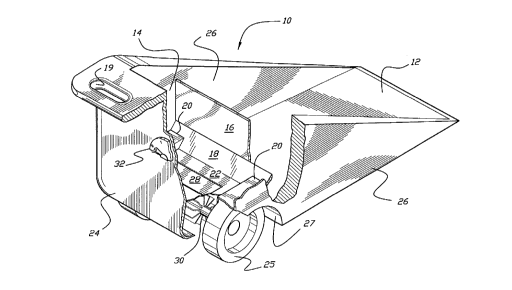
Figure 1 is a perspective cut-away view of the snow
barrow;
Figure 2A is a perspective view of a portion of the
track dispersement axle;
Figure 2B is a cross-sectional view of the track
dispersement axle;
Figure 2C is a perspective view of a portion of the
pinwheel dispersement axle;
Figure 2D is a cross-sectional view of the pinwheel
dispersement axle;
Figure 3 is a perspective cut-away view of the salt
dispensing system;
Figure 4 is a perspective view of the push board;
and
Figure 5 is a side elevational view of the storage
receptacle.
Similar reference characters denote corresponding
features consistently throughout the attached
drawings.


CA 02214621 2000-02-04
4
DETAILED DESCRIPTION OF THE PREFERRED EMBODIMENTS
Figure 1 shows the snow barrow 10 of substantially uniform
construction defining a pair of rear wheel wells 27 for housing
a pair of rear wheels 25 (only one of each pair is shown). The
basic components of the show barrow 10 are the snow scooping
compartment 12, the salt storage and dispensing compartment 14,
and the partition 16 dividing the two compartments 12 and 14.
The handles 19 (only one is shown) allow a user to easily push
the barrow 10. Other components will be discussed below in
conjunction with the discussion of the salt dispensing system.
Figure 3 shows the salt dispensing system 38. The
dispensing system 38 includes the salt storage and dispensing
compartment 14, which is bounded by partition 16, sloping wall
18, wheel wells 20, 20 (only one shown in Figure 3),
compartment bottom 23, rear wall 24, and side walls 26, 26
(only one shown in Figure 3). The sloping wall 18 slopes from
a lower portion of the partition 16 to the fixed portion 22 of
the compartment bottom 23 and prevents salt from accumulating
in the lower corner formed by the intersection of the partition
16 and the fixed portion of the bottom 23. The dispensing
system 38 includes a door 28 swingably mounted to the fixed
portion 22 of the dispensing compartment bottom 23. The salt
falls through the door 28 onto the axle, which can be either
a track dispersing axle 30 (as seen in more detail in Figures
2A and 2B) or a pinwheel dispersing axle 34 (as seen in Figures
2c and 2D).
The opening of the door 28, which is mounted on hinges,
is controlled by the weight of the salt and a tension system
32, which is attached to the door 28. The tension system 32
includes a lever which rotates along a gauge and a tension
cable, preferably a nylon cord, which is connected at one end
to the lever and at the other end to the door 28. As the lever
is rotated clockwise along the gauge (to a higher number), the
tension applied to the door 28 is decreased, allowing it to
open further. Tension


CA 02214621 1997-09-04
adjustments can be used to compensate for the changing
weight of the salt as it is dispensed.
Figure 5 shows a storage receptacle 50 for the
vertical storage of the snow barrow 10 or the push
5 board 40 (seen in Figure 4). The storage receptacle
50 has a triangular-shaped opening 52 for receiving
the nose of a snow removal device. Nose holders 54,
54 secure the snow removal device into the storage
receptacle 50.
It is to be understood that the present invention is
not limited to the embodiments described above, but
encompasses any and all embodiments within the scope
of the following claims .

Representative Drawing
A single figure which represents the drawing illustrating the invention.
Administrative Status

For a clearer understanding of the status of the application/patent presented on this page, the site Disclaimer , as well as the definitions for Patent , Administrative Status , Maintenance Fee  and Payment History  should be consulted.

Administrative Status

Title Date
Forecasted Issue Date 2000-12-26
(22) Filed 1997-09-04
Examination Requested 1997-09-04
(41) Open to Public Inspection 1998-03-05
(45) Issued 2000-12-26
Deemed Expired 2005-09-06

Abandonment History

There is no abandonment history.

Payment History

Fee Type Anniversary Year Due Date Amount Paid Paid Date
Request for Examination $200.00 1997-09-04
Application Fee $150.00 1997-09-04
Maintenance Fee - Application - New Act 2 1999-09-07 $50.00 1999-09-01
Maintenance Fee - Application - New Act 3 2000-09-05 $50.00 2000-09-05
Final Fee $150.00 2000-09-20
Maintenance Fee - Patent - New Act 4 2001-09-04 $50.00 2001-09-04
Maintenance Fee - Patent - New Act 5 2002-09-04 $75.00 2002-08-16
Maintenance Fee - Patent - New Act 6 2003-09-04 $75.00 2003-09-04
Owners on Record

Note: Records showing the ownership history in alphabetical order.

Current Owners on Record
SINCLAIR, SYLVESTER JR.
Past Owners on Record
None
Past Owners that do not appear in the "Owners on Record" listing will appear in other documentation within the application.
Documents

To view selected files, please enter reCAPTCHA code :


To view images, click a link in the Document Description column. To download the documents, select one or more checkboxes in the first column and then click the "Download Selected in PDF format (Zip Archive)" or the "Download Selected as Single PDF" button.

List of published and non-published patent-specific documents on the CPD .

If you have any difficulty accessing content, you can call the Client Service Centre at 1-866-997-1936 or send them an e-mail at CIPO Client Service Centre.


Document
Description 
Date
(yyyy-mm-dd) 
Number of pages   Size of Image (KB) 
Description 2000-02-04 5 193
Claims 2000-02-04 2 56
Abstract 1997-09-04 1 27
Description 1997-09-04 5 185
Claims 1997-09-04 2 63
Drawings 1997-09-04 5 144
Cover Page 1998-03-17 2 76
Cover Page 2000-12-05 1 71
Representative Drawing 1998-03-17 1 22
Representative Drawing 2000-12-05 1 24
Prosecution-Amendment 2000-02-04 7 233
Fees 2003-09-04 1 45
Correspondence 2000-09-20 1 61
Assignment 1997-09-04 2 105
Prosecution-Amendment 1999-08-05 3 5
Fees 2000-09-05 1 56
Fees 2001-09-04 1 58
Fees 2002-08-16 1 57
Fees 1999-09-01 1 59