Note: Descriptions are shown in the official language in which they were submitted.
CA 02214820 1998-11-24
335-3
A8R~SIVE SLURRY HANDLING VALVES
Bac~qround of the Invention
Field of the ~nvention. The present invention
relates to the handling of abrasive slurries and the like, and
more particularly to valves for use in pumps adapted for the
handling of abrasive slurries and the like.
10DescriPtion of the Prior Art. Valves for use in
pumps especially adapted for the handling of abrasive slurries
and the like are well known in the prior art.
An example of such a valve is shown and described in
United States Patent No . 5 ,193, 577 which was issued to
15Cornelis ~. de Koning on March 16, 1993, and entitled SLUDGE
PUMP VAI.VE.
A stated object of the invention of the de Koning
patent is to provide a valve "which has a longer life and a
longer maintenance-free period than the valves of the prior
art".
However, field experience with valves embodying the
invention of the de Koning patent (hereinafter "de Koning
valve") and examination of such valves after the expiration of
their respective full service lives, indicates that the
2~ asserted freedom from maintenance and long life thereof
CA 02214820 1998-11-24
results at ]east in part from the fact that the de Koning
valve is essentially non-repairable.
That is to say, the primary rubber seal of the de
Koning valve is bonded, as by vulcanizing, to the metal of the
valve core, and thus recycling of the worn metallic core is
both mechanically and chemically impractical.
Thus, since the de Koning valve is essentially non-
repairable, the user of de Koning valves must make a large
initial investment in valves which must be discarded after a
service life of perhaps 900 hours.
It is also well known in the prior art, e.g., in the
valves of the Melott, Campbell, and Johnson patents listed in
the accompanying Information Disclosure Statement, to
incorporate guiding legs or the like into the moving valving
members of abrasive slurry handling valves. Conventionally,
such guiding legs or the like are rebuilt for reuse of the
valving member by weld buildup and remachining. In a valve of
the de Koning type, however, such weld buildup and remachining
is impractable, because the heat produced by such extensive
welding would be very likely to completely destroy the bonded
rubber valve seat facing.
As is well known to those having ordinary skill in
the art, these prior art valves are used in applications which
vary widely in operating conditions, such as the corrosiveness
and abrasiveness of the slurry being pumped.
CA 02214820 1998-11-24
This is a result of the particular combination of
chemicals which must be used to extract the product (such as
gold) from the finely ground ore which constitutes the
particulate part of the slurry. The slurry processed at one
particular mine may, for example, have a pH of 2.0 and a
particle size of minus 200 mesh. The slurry processed at
another mine may have a pH of 5.0, but a larger particle size,
e.g., 100 mesh.
No available metal alloy (for metallic pump parts)
and no available elastomeric material (for resilient pump
parts), and no available combination of alloy and elastomer,
can meet the requirements of every type of pump service, and
thus integral, or non-modular valving members, as taught in de
Roning, offer almost no adaptability to the broad range of
requirements of slurry pump users.
It is believed that the documents listed in the
Inf-ormatiosl Disclosure Statement submitted herewith contain
information which is or might be considered to be material to
the examination hereof.
The term "prior art" as used herein or in any
statement made by or on behalf of applicant means onl~ that
any document or thing referred to as prior art bears, directly
or inferelltially, a date which is earlier than the effective
filing date hereof.
No representation is made that any of the documents
listed in the accompanying Information Disclosure Statement is
CA 02214820 1998-11-24
part of the prior art, or that a search has been made, or that
no more pertinent information exists.
SummarY of the Inventi on
Accordingly, it is an object of the present
invention to provide abrasive slurry handling valves the
service lives of which far exceed the service lives of the
abrasive slurry handling valves of the prior art.
Another object of the present invention is to
provide abrasive slurry handling valves which are readily
customized to meet the respective requirements of a very wide
variety of service conditions.
Yet another object of the present invention is to
15 provide abrasive slurry handling valves which are readily
rebuildable at relatively low cost, thus greatly reducing the
service life cost of any such valve.
A further object of the present invention is to
provide a new type of abrasive slurry handling valve by the
use of which the weld buildup and remachining of valve parts
during rebuilding is reduced or completely eliminated.
Yet another object of the present invention is to
provide a new type of abrasive slurry handling valve which can
be very rapidly rebuilt, thus reducing pump down time or the
alternative need to stock extra sets of spare valves.
.
CA 02214820 1998-11-24
Another object of the present invention is to
provide abrasive slurry handling valves including elastomeric
auxiliary sealing means which close prior to the contacting of
the associated metallic valve faces, and thus reduce the
S lapping of said metallic valve faces which otherwise would
result from the passage of slurry particles between closely
spaced metallic valve faces.
Yet another object of the present invention is to
provide a new type of abrasive slurry handling valves in which
a minimum number of elastomeric parts are bonded to adjacent
metallic parts by vulcanizing or the like.
A further object of the present invention is to
provide a new type of abrasive slurry handling valve in which
the metallic and elastomeric seating and sealing faces reach
the ends of their respective service lives, i.e., wear out,
substantially simultaneously.
A yet further object of the present invention is to
avoid undue wear of the elastomeric seating and sealing faces
of the valves thereof occasioned by linear or small area
initlal contact at the outer edges of said faces during valve
cl oslng .
Another object of the present invention is to
eliminate the undue wear resulting from the outer edges of
elastomeric sealing members grippingly engaging associated
metallic members and sliding thereover.
--5--
CA 02214820 1998-11-24
Yet another object of the present invention is to
provide, in an abrasive slurry handling valve, ejecting means
for ejecting slurry particulate from between the resilient
contacting faces of the valve as the valve closes.
Other objects of the present invention will in part
be obvious, and will in part appear hereinafter.
The present invention, accordingly, cQmprises the
apparatus embodying features of construction, combinations of
elements, and arrangements of parts exemplified in the
following disclosure, and the scope of the present invention
will be indicated in the claims appended hereto.
In accordance with a principal feature of the
present invention the moving valving member of an abrasive
slurry handling valve thereof consists of three principal
parts which are joined together by means of a single weld
bead.
In accordance with another principal feature of the
present invention said three principal parts of said valving
member can be detached from each other by grinding out said
single weld bead.
In accordance with yet another principal feature of
the present invention a first one of said principal parts is
an upper sealing ring which is clamped between said other two
principal parts.
In accordance with a further principal feature of
the present invention a second one of said principal parts is
. . ,
CA 02214820 1998-11-24
essentially comprised of a lower jaw for use in clamping said
first one of said principal parts in its operative position
and a plurality of valve member guide legs.
In accordance with a yet further principal feature
S of the present invention a third one of said principal parts
consists essentially of an upper jaw adapted to cooperate with
said lower jaw to clampingly engage said first principal part,
a valve stem, and aligning means for aligning said upper jaw
and said lower jaw.
In accordance with another principal feature of the
present invention the outer end of said aligning means
cooperates with the main body of said second one of said
principal parts to define a channel in which to deposit said
weld bead.
In accordance with yet another principal feature of
the present invention said upper valve sealing ring (said
first principal part) is of generally toroidal configuration,
is principally composed of elastomeric material; and has a
frustoconical outer face which serves as the resilient sealing
face of the valve of the invention.
In accordance with a further principal feature of
the present invention a substantially rigid toroidal
reinforcing member is molded into the toroidal elastomeric
body of said upper sealing ring.
In accordance with a yet further principal feature
of the present invention a generally toroidal auxiliary
CA 02214820 1998-11-24
sealing lip projects outwardly and upwardly from the said
elastomeric portion of said upper sealing ring, along the
upper edge of said frustoconical outer face thereof.
In accordance with another principal feature of the
present invention said auxiliary sealing lip is reinforced by
an outer portion of said reinforcing member.
In accordance with yet another principal feature of
the present invention a circular channel is defined by the
inner surface of said auxiliary sealing lip and the outer
surface of said upper jaw, said channel being adapted to
contain slurry under pressure when the valve is completely or
substantially completely closed, said slurry under pressure
then serving to forcibly expand said auxiliary sealing lip
until it contacts the elastomeric seating ring of the valve
and thus prevents the lapping of the associated rigid metallic
valve faces by leakage of slurry therebetween.
. .
For a fuller understanding of the nature and objects
of the present invention, reference should be had to the
following detailed description, taken in connection with the
claims appended hereto.
Brief DescriPtion of the Drawinqs
Fig. 1 is an exploded perspective view of the
principal novel parts of an abrasive slurry handling valve of
the first preferred embodiment of the present invention;
. . . , , _ _
CA 02214820 1998-11-24
Fig. 2 is a vertical sectional view of the third
principal part of the valving member of the valve of the first
preferred embodiment of the present invention;
Fig. 3 is a vertical sectional view of the second
principal part of the valving member of the valve of the first
preferred embodiment of the present invention;
Fig. 4 is a cross-sectional view of the first
principal part of the valve of the first preferred embodiment
of the present invention;
Figs. S and 6 are cross-sectional views of the two
parts of the lower sealing ring of the valve of the first
preferred embodiment of the present invention;
Fig. 7 is a cross-sectional view of the valve seat
body of the first preferred embodiment of the present
invention;
Fig. 8 is a cross-sectional view of a complete
abrasive slurry handling valve of the first preferred
embodiment of the present invention;
Fig. 9 is a perspective view, partly in section, of
the first principal part of the valving member of the valve of
the first preferred embodiment of the present invention;
Fig. 10 is a perspective view, partly in section, of
the lower sealing ring of the valve of the first preferred
embodiment of the present invention;
Fig. 11 is a partial sectional view of the valve of
the first preferred embodiment of the present invention shown
.. .. . ..
CA 02214820 1998-11-24
in Fig. 8, particularly illustrating the configuration of the
contact faces of the valve of the first preferred embodiment
of the present invention;
Fig. 12 is a partial sectional view of the valve of
the second preferred embodiment of the present invention;
Fig. 13 is a partial sectional view of the valve of
the third preferred embodiment of the present invention; and
Fig. 14 is a partial sectional view of the valve of
the fourth preferred embodiment of the present invention.
Description of the Preferred Embodiments
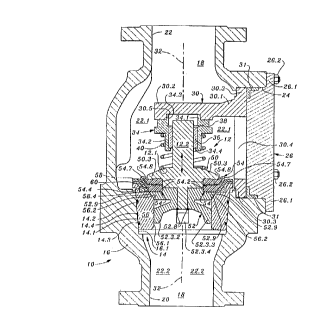
Referring now to Fig. 1, there are shown the novel
parts of a valve constructed in accordance with the first
preferred embodiment of the present invention.
A valve 10 in which said novel parts are
incorporated is shown in Fig. 8.
In the manner well known to those having ordinary
skill in the valve art, valve 10 (Fig. 8) is comprised of a
movable valving member or valve element 12 and a valve seat
14, both of which are contained in a valve body 16.
As further seen in Fig. 8, valve body 16 defines a
fluid flow passage 18 which extends ~rom the lower (as seen in
Fig. 8) port or intake port 20 of valve 10 to the upper (as
seen in Fig. 8) port or discharge port 22 of valve 10.
-10 -
., ~
CA 02214820 1998-11-24
Also in the known manner, valve body 16 is provided
with a service port 24 through which valving member 12 and
valve seat 14 may be withdrawn from or inserted into valve
body 16, and through which debris may be removed from the
interior or valve body 16.
Service port 24 is normally fluid-tightly closed by
means of a service port cover 26 which is maintained in its
operative position by nuts 26.2 which coact with suitable
studs which pass through clearance holes (3) in cover flange
26.1, and is sealed to the wall of service port 24, against
fluid leakage, by means of a suitable gasket 31.
Many alternative forms of service port cover gasket,
and many alternative means of retaining service port cover 26
in its operative position, will occur to those having ordinary
lS skill in the art.
As also seen in Fig. 8, valve 10 is further
comprised of a valve guide support 30 which is an integral,
rigid member principally comprised of a support arm 30.1, a
valve guide receiver 30.2 and a body ring 30.3, which defines
a service aperture 30.4.
In the known manner, valve guide receiver 30.2 is
generally discate in form and is provided in its iower face
with a well 30.5 which is adapted to close-fittingly receive
the upwardly projecting circular flange portion 34.1 of the
valve guide 34.
--11 -
CA 02214820 1998-11-24
The valve guide receiver portion 30.2 of valve guide
support 30 is generally discate in form and is generally
symmetrical about the central axis 32 of passage 18.
As also seen in Fig. 8, valve guide 34 is provided
with a downwardly projecting (as seen in Fig. 8) cylindrical
flange portion 34.2 which close-fittingly contains a
cylindrical valve guide bushing 36. Valve guide bushing 36 is
retained in the central, generally cylindrical, bore 34.3 of
valve guide 34 by means of a lip 34.4 and a suitable snap ring
38. As will be evident to those having ordinary skill in the
valve art, informed by the present disclosure, valve guide 34
is generally cylindrical in form, and is generally symmetrical
about axis 32, as is valve guide bushing 36. Valve guide
bushing 36 is formed from suitable metallic material such as
duplex alloy CD4. Alternatively, in accordance with the
present invention, ACM or another suitable thermoplastic
composition may be substituted for metallic material.
As seen in Fig. 8, valve 10 is further comprised of
a valve spring 40, which is a spiral compression spring of
sufficient force to firmly thrust valving member 12 against
valve seat 14. The lower end of valve spring 40 is maintained
in coaxial relationship with valving member 12 by engagement
with a boss 12.1 which is raised on valve element 12. The
upper end of valve spring 40 fits loosely around downwardly
projecting cylindrical flange portion 34, discussed
hereinabove.
-12-
,
CA 02214820 1998-11-24
As also seen in Fig. 8, the upwardly projecting stem
portion 12.2 of valving member 12 is close-fittingly, slidably
received in valve guide bushing 36, whereby the axis of
symmetry of valving member 12 is maintained substantially
coincident with valve body axis 32, and with the axis of
symmetry of valve seat 14. (Valve 10 further comprises other
means for maintaining the axis of symmetry of valve element 12
and the axis of symmetry of valve seat 14 in substantial
coincidence, which other means will be described in detail
hereinafter.)
As also seen in Fig. 8, valve body 16 is provided
with a conical inner surface portion 16.1 which is adapted to
receive and support valve seat 14. Valve seat 14 is generally
cylindrical in form and is provided with an outer surface 14.1
which is of conical configuration, and which has the same
apical angle as surface portion 16.1 of valve body 16.
Valve seat 14 is provided, in the well known manner,
with two channels in outer face 14.1, which channels contain
suitable O-rings 14.2, 14.3. An intermediate channel 14.4,
not containing an O-ring, is provided in outer face 14.1 for
use in freeing valve seat 14 from face 16.1 by the use of
fluid pressure, in the well known manner.
Referring again to Fig. 8, it will be seen that
valve element 12 is comprised of an upper jaw 50, a lower jaw
52 and a sealing ring 54 (sometimes called herein the "upper
sealing ring").
-13-
CA 02214820 1998-11-24
As also seen in Fig. 8, seat (or "seat assembly")
14 is comprised of a seat body 56, a lower sealing ring 58, a
backing ring 60 and O-rings 14.2 and 14.3.
Referring now to Fig. 1 there are shown an upper jaw
550, lower jaw 52, upper sealing ring 54, seat body 56, lower
sealing ring 58 and backing ring 60.
As seen in Fig. 1, upper sealing ring 54, lower
sealing ring 58 and backing ring 60 are all substantially
ring-shaped or toroidal, the cross-sectional configuration of
10each being a particular feature of the present invention.
Seat body 56 is generally of toroidal configuration,
and the cross-sectional configuration thereof is determined in
accordance with the principles of the present invention.
As best seen by comparison of Figs. 1 and 2, upper
15jaw 50 is a unitary member including an upwardly projecting
stem portion 12.2 of generally circular cross-section, a
downwardly projecting neck portion 50.1, of generally circular
cross-section and a central body portion 50.2 from which
projects a lip portion 50.3. The lower or outer end of neck
20portion 50.1 is provided with a chamfer 50.4 the purpose of
which will be disclosed hereinafter.
As discussed hereinabove in connection with Fig. 8,
and seen in detail in Fig. 2, boss 12.1 is provided on the
upper face of central body portion 50.2.
25As best seen in Fig. 2, the underside of lip portion
50.3 is provided with a toroidal concavity 50.5.
CA 02214820 1998-11-24
As may also be seen by comparison of Figs. 1 and 2,
central body portion 50.2 of upper jaw 50 has a planar lower
face 50.6 from which neck 50.1 projects.
Jaw 50 may, in accordance with the inventi on, be
formed from duplex alloy CD4, or in some cases from mild
steel.
As best seen by comparison of Figs. 1 and 3, lower
jaw 52 is a unitary member including a lower jaw body portion
52.1 which is generally discate in form, a generally
cylindrical spider body portion 52.2 which projects downwardly
from lower jaw body portion 52.1, and four spider leg portions
52.3.1, 52.3.2, 52.3.3, 52.3.4 which project downwardly and
outwardly from spider body portion 52.2.
As best seen in Fig. 3, a bore 52.4 extends axially
through lower jaw 52, from planar upper face 52.5 to planar
lower face 52.6, and the lower end of bore 52.4 is provided
with a chamfer 52.7. Chamfer 52.7 is of substantially the
same cross-sectional dimension as cooperating chamfer 50.4
(Fig. 2). Thus, it will be understood by those having
ordinary skill in the art, informed by the present disclosure,
that chamfers 52.7 and 50.4 together form a channel in which
a circular weld bead 52.8 is deposited (Fig. 8) after the
three parts of valve element 12 are assembled in the
collocation shown in Fig. 8. Thus, as will be evident to
those having ordinary skill in the art, informed by the
present disclosure, circular weld bead 52.8 (Fig. 8) ~erves to
._
CA 02214820 1998-11-24
join the parts 50, 52 and 54 together in their intended
cooperative relationship.
Again comparing Figs. 1 and 3, it will be seen that
the outer face 52.9 of lower jaw body portion 52.1 takes the
form of a frustum of a cone. As seen in Fig. 8, outer face
52.9 serves as a sealing face of valve 10, and cooperates with
seating face 56.2 (Fig.8) of seat body 56 to block passage 18.
It will also be seen (Fig. 3) that lower jaw body portion 52.1
has a planar lower face 52.10.
As further seen in Fig. 8, the outer ends of legs
52.3.1, 52.3.2, 52.3.3, and 52.3.4 are close-fittingly
received in the central bore 56.1 of seat body 56, and thus
serve to maintain valve element 12 coaxial with valve seat 14.
As best seen by comparison of Figs. 1, 4 and 9,
upper sealing ring 54 is generally toroidal in configuration,
and consists of a reinforcing ring 54.1 upon which is molded
an upper sealing ring body 54.2 of a suitable elastomeric
material such as natural rubber, Viton, or the like.
As further seen in Fig. 4, upper sealing ring body
54.2 is provided with a generally frustoconical outer face
54.4 which is symmetrical about an axis 54.5.
As yet further seen in Fig. 4, upper sealing ring
body 54.2 is also provided with a central aperture 54.6 the
wall of which is of the form of a right circular cylinder the
axis of which is coincident with the abovesaid axis 54.5.
-16-
CA 02214820 1998-11-24
As best seen in Fiq. 4, the elastomeric body portion
54.2 of upper sealing ring 54 is provided with a generally
domed upper surface 54.3 which closely fits into toroidal
concavity 50.5 (Fig. 2) when upper sealing ring 54 is clamped
between upper jaw 50 and lower jaw 52, as seen in Fig. 8.
As also seen in Fig. 4, upper sealing ring 54 is
provided with a circular lip 54.7, which is integral with
upper sealing ring body 54.2 and projects upwardly therefrom.
Lip 54.7 contains the outer edge of reinforcing ring 54.1.
As seen in Fig. 8, a toroidal pocket 54.8 is defined
between lip 54.7 and the outer surface of lip 50.3. This
toroidal pocket (54.8) contains slurry under pressure when
discharge chamber 22.1 (Fig. 8) is filled with slurry under
pressure, and thus serves to apply outward pressure to lip
54.7, and to apply downward pressure to the outer portion of
ring body 54.2. These outward and downward pressures serve,
repectively, to press the outer face of lip 54.7 against the
adjacent part of the lower sealing ring 58, and to press the
outer face 54.4 of ring body 54.2 against the inner face 58.4
of lower sealing ring 58, whereby to prevent the leakage of
slurry from discharge chamber 22.1 to intake chamber 22.2 if
metallic contact surfaces 52.9 and 56.2 are held slightly
apart by solid particles of the slurry, and thus to prevent
erosion of surfaces 52.9 and 56.2 by the passage thereover of
the leaking slurry.
CA 02214820 1998-11-24
Referring now to Figs. 1, 7 and 8, it will be seen
that seat body 56 is a unitary body of metallic material such
as CD4 or mild steel.
As best seen in Fig. 7, seat body 56 is provided on
5its outer surface 56.3 with two grooves or channels 56.4, 56.5
adapted to close-fittingly contain the O-rings 14.2, 14.3
shown in Fig. 8.
It is to be particularly noted that cylindrical
inner surface 56.6 of seat body 56 (Fig. 7), and frustoconical
10inner surface 56.7, are critical surfaces which must be turned
to close tolerances, since backing ring 60 (Fig. 6) is to be-
retained in seat body 56 by press fitting, and thus the
diameter of the cylindrical surface 56.6 of seat body 56 (Fig.
7) must be precisely matched to the diameter of outer
15cylindrical surface 60.1 of backing ring 60 (Fig. 6).
Similarly, the angular and linear dimensions of
inner frustoconical surface 56.7 of seat body 56 (Fig. 7) and
the angular and linear dimensions of outer frustoconical
surface fiO.2 of backing ring 60 (Fig. 6) must be precisely
20matched in order to avoid interference with the proper seating
of backing ring 60 when it is press-fitted into seat body 56.
As best seen in Fig. 8, the dimensions of
frustoconical inner face 56.2 of seat body 56 must conform to
a high degree to the dimensions of the outer frustoconical
25surface 52.9 of lower jaw 52.
-18-
CA 02214820 1998-11-24
As best seen in Fig. 6, backing ring 60 is also
provided with a precisely turned inner frustoconical surface
60.3, a planar, toroidal upper surface 60.4, and a planar,
toroidal lower surface 60.5, which must be machined to close
tolerance.
Backing ring 60 is preferably fabricated from duplex
metallic alloy CD4.
As best seen by comparison of Figs. 1, 5, 8 and 10,
lower sealing ring 58 is a generally toroidal body molded from
suitable elastomeric material such as Viton or the like.
As best seen in Fig. 5, lower sealing ring 58 is
formed with a planar, toroidal lower surface 58.1 and a
planar, toroidal upper surface 58.2 which forms the upper
surface of the circular flange portion 58.3 of lower sealing
ring 58.
As also seen in Fig. 5, lower sealing ring 58 has a
frustoconical inner surface 58.4, and a frustoconical outer
surface 58.5.
As best seen in Fig. 9, reinforcing ring 54.1 of
upper sealing ring 54 is a unitary, toroidal metallic member
comprised of a generally frustoconical outer flange portion
54.1.1 and a toroidal inner portion 54.1.2 which is itself
formed as a plurality of peaks and intervening depressions or
valleys.
As particularly seen in Fig. 10, lower sealing ring
58 close-fittingly contacts backing ~ing 60 along a common
--19-
.
CA 02214820 1998-11-24
interface 61. It is to be understood that, in accordance with
the present invention, lower sealing ring 58 is vulcanized to
backing ring 60 substantially completely throughout common
interface 61.
Referring now to Fig. 11, there is shown a partial
cross-sectional view of that part of valve 10 of the first
preferred embodiment of the present invention immediately
adjoining one element, i.e., one generatrix location, 68 of
the contact locus or valve interface 70 of valve 10 of the
first preferred embodiment.
As will be evident to those having ordinary skill in
the art, informed by the present disclosure, the configuration
of the contact locus or valve interface 70 of valve 10 of the
first preferred embodiment is that of the frustum of a cone
the axis of which coincides with axes 32 (Fig. 8) and 54.5
(Fig. 4).
It is also to be noted that, in accordance with a
principal feature of the first preferred embodiment of the
present invention, element 68 can be considered to be divided
into two sub-elements 68' and 68'' which meet at point 76
(Fig. 11).
Thus, it will be seen that interfac~ 70 is a
compound interface and is divided into an outer interface 72
and an inner interface 74, both of which are of frustoconical
form, and which together are congruent with compound interface
70.
-20~
CA 02214820 1998-11-24
It will thus be seen in Fig. 11 that when valve 10
is fully closed the area of contact between elastomeric
sealing face 54.4 and elastomeric seating face 58.4 coincides
with outer contact locus or interface 72, and that the area of
contact between rigid, metallic sealing face 52.9 and rigid,
metallic seating face 56.2 coincides with inner contact locus
or interface 74.
In view of the above it will be understood by those
having ordinary skill in the art that the valves of the first
preferred embodiment of the present invention, including valve
10, are characterized by a compound contact locus or valve
interface (70 in valve 10) which is comprised of an outer
contact locus or interface (72 in valve 10) and an inner
contact locus or interface (74 in valve 10), and that the~e
contact loci or interfaces have a common circular boundary 76,
one point of which (76) is shown in Fig. 11.
It is also to be noted that the inclination (angle
S, Fig. 11) of the generatrix of interface 70 to a plane
perpendicular to axis 32 (Fig. 8) is large, about 55 degrees,
i.e., the apex angle is small, about 35 degrees.
rt is further to be noted, as a particular feature
of the present invention, that when the two frustoconical
elastomeric faces, 54.4 and 58.4, are in contact (valve 10
closed), the two rigid, frustoconical metallic faces 56.2 and
52.9, are also in contact.
CA 02214820 1998-11-24
As seen in Fig. 12, a valve 100 of the second
preferred embodiment of the present invention is assembled,
except as noted below, from parts which are substantially
identical to the corresponding parts of valve 10, and thus are
indentified by the same reference numerals used to designate
the respective corresponding parts of valve 10.
In valve 100, however, upper sealing ring 154
differs from upper sealing ring 54 of valve 10 in that the
frustoconical elastomeric face 154.4 of ring 154 has a
slightly smaller apex angle than the apex angle of
frustoconical elastomeric face 58.4, and thus metallic faces
56.2 and 52.9 will come into contact (during the closure of
valve 100) before the frustoconical elastomeric faces 154.4
and 58.4 of valve 100, or at least the upper parts thereof,
come into contact. Thus, at least during the initial "wearing
in" process of a newly made or rebuilt valve, the tapered gap
102 between frustoconical elastomeric faces 154.4 and 58.4
will, as valve 100 closes, tend to produce an ejecting action
whereby slurry particles are ejected from this gap (102). The
closing of tapered gap 102, as valve closure is completed,
will result from the expansion of elastomeric ring body 154.2
by f luid pressure in toroidal pocket 54.8, which is a
principal feature of the present invention, discussed
hereinabove in conection with Fig. 8. Thus, it will be seen
that in valve 100 of the second preferred embodiment of the
present invention the ~ast contact between the two
-22-
. _
CA 02214X20 1998-11-24
,
frustoconical elastomeric sealing faces, during valve closure,
will take place between the radially outermost portions (104,
106) of those frustoconical faces, which is the very opposite
of the closing action of the valves of United State-~ Patent
No. 5,193,577.
In the second preferred embodiment the angle
subtended at point 76 (Fig. 12) between faces 154.4 and 58.4
when faces 56.2 and 52.9 are in contact but upper sealing ring
154 is not distorted by slurry pressure in toroidal channel
54.8, may in some embodiments fall into the range of one
degree to three degrees.
Referring now to Fig. 13, there is shown a valve 200
of the third preferred embodiment of the present invention.
Valve 200 is assembled from parts which are substantially
identical to the corresponding parts of valve 10, except as
noted hereinbelow, and these common parts are identified by
the same reference numerals used to designate the respective
corresponding common parts of valve 10 of the first preferred
embodiment of the present invention.
In valve 200, however, upper sealing ring 254 (Fig.
13) is substituted for upper sealing ring 54 (Fig. 8), and
upper jaw 250 is substituted for upper jaw 50 (Fig. 8).
As seen in Fig. 13, upper sealing ring 254 does not
include a lip corre~ponding to the lip 54.7 shown ln Fig. 8.
Further, the body 254.2 of upper sealing ring 254 contains a
backing ring 254.4 whiJh is generally toroidal in shape, and
_,
CA 02214820 1998-11-24
is preferably fabricated from rigid metallic material. Also
contained in body 254.2 is a toroidal passage 254.6 which is
filled with a suitable hydraulic fluid 254.8 having a thermal
coefficient of expansion matching as closely as possible the
5thermal coefficient of expansion of the elastomeric material
from which the body 254.2 of upper sealing ring 254 i5 formed.
It is also to be noted in Fig. 13 that a plurality
of openings 250.2 are provided in the outer part of upper jaw
250 in order to provide access to the upper face 254.12 of
10upper sealing ring 254 for pumped slurry under pressure. The
number, angular extent, and radial depth of openings 250.2 is
determined empirically when adapting a valve 200 of the
present invention to the requirements of a particular pump and
pumping application.
15As will now be seen by those having ordinary skill
in the art, informed by the present disclosure, downward
pressure exerted by slurry under pressure on the upper surface
254.12 of ring 254 serves to force toroidal, frustoconical
sealing face 254.10 outward, thus normally pressing face
20254.10 against face 58.4 of lower sealing ring, i.e., seating
ring, 58 (Fig. 8) without sliding friction between faces
254.10 and 58.4 (Fig. 8).
Referring now to Fig. 14, it will be seen that valve
300 of the fourth preferred embodiment of the present
25invention is substantially identical to valve 200 of the third
preferred embodime~t, with the exception that upper sealing
-24-
. : , . .. .
CA 02214820 1998-11-24
ring 354 of the fourth preferred embodiment does not contain
a backing ring similar to backing ring 254.4 of the third
preferred embodiment. Rather, a toroidal backing portion
352.1 is provided which is integral with lower jaw 352, the
extent of the added portion 352.1 being delineated by dashed
lines 352.2, 352.3, and the cross-section of riny 354 being
generally L-shaped.
In accordance with another principal feature of the
present invention, as best seen in Fig. 12, a toroidal insert
156.2 is provided in lower jaw 56. Toroidal insert 156.2
bears on its outer face the metallic seating face 56.2, and
thus seating face 56.2, when worn, may be replaced by
replacing only toroidal insert 156.2, rather than replacing
the entire valve seat 56, and may be held in place by press
fitting, without welding or the like.
It will thus be seen that the objects set forth
above, among those made apparent from the preceding
description, are efficiently attained, and since certain
changes may be made in the above constructions without
departing from the scope of my present invention, it is
intended that all matter contained in the above description or
shown in the accompanying drawings shall be inteFpreted as
illustrative only, and not in a limiting sense.
It is also to be understood that the following
claims are intended to cover all of the generic and specific
features of my ~nvention hereindescribed, and all statements
-25-
CA 02214820 1998-11-24
.
of the scope of my invention which, as a matter of language,
might be said to fall therebetween.
-26-