Note: Descriptions are shown in the official language in which they were submitted.
CA 02214873 1997-09-09
.
8URGICAL SYSTEM FOR TISSUE RENOVAL
BACRGROUND
1. Technical Field
The present disclosure relates to apparatus and
method for biopsy/removal of tissue from within a
patient's body. More particularly, the present
disclosure relates to apparatus and method for breast
tissue biopsy/removal. The present disclosure further
relates to a system for tissue removal and more
particularly to a drive system for surgical cutting
instruments.
CA 02214873 1997-09-09
2. Background of Related Art
Numerous surgical instruments have been developed
for performing minimally invasive surgical procedures.
Such procedures greatly reduce recovery time for the
patients in comparison to conventional open surgical
procedures. Minimally invasive instruments also reduce
damage to tissue surrounding the operative site. The
enormous success of such instruments in procedures such
as gall bladder removal and hernia repair has led to
increased development of minimally invasive instruments
for other operative procedures as well.
One area where minimally invasive instruments have
been utilized is in performing biopsies of target breast
tissue to determine whether the tissue is malignant or
benign. As is quite often the case, lesions within the
breast are non-palpable, therefore, making cancerous
lesions more difficult to diagnose. Early diagnosis of
suspect lesions in a patient's breast, however, has been
greatly enhanced through the development of imaging
machines, for example, stereotactic mammography imaging
systems (hereafter referred to as "stereotactic
machines"). In such machines, an elongated prone
supporting examining table for x-ray mammography is
provided with a central breast receiving aperture,
through which the patient's pendulant breast is exposed
to a horizontal beam of x-rays from a source which is
CA 02214873 1997-09-09
angularly movable through an arc centered on the
patient's breast. Thus, x-ray projection through more
than 360 degrees around the patient's body is possible.
An example of such a stereotactic machine is disclosed in
U.S. Patent No. 5,289,520 which issued on February 22,
1994 to Pellegrino et al., the contents of which are
hereby incorporated by reference.
Fine needle biopsy is also facilitated by
stereotactic machines. In such procedures, doctors can
take advantage of the precision instrument positioning
and suspect tissue position locating capabilities of the
machine's imaging systems, to precisely insert a biopsy
needle and retrieve a tissue sample.
However, minimally invasive instrumentation to
lS efficiently and efficaciously biopsy and/or remove tissue
so as to potentially avoid open surgical techniques are
not readily available. The present disclosure provides
minimally invasive apparatus which are relatively easy to
use and inexpensive to reliably manufacture and use. The
present disclosure also provides apparatus and method(s)
for removing breast tissue using minimally invasive
techniques.
one issue sometimes encountered in the removal of
tissue by way of a rotational or coring motion is that,
during rotation of the cutting portion of the instrument,
a spiraling of the tissue can occur as the cutting edge
CA 02214873 1997-09-09
moves along the surface of and through the tissue. In
particular, as the cutting edge passes along the surface
of the tissue, the tissue sometimes moves "momentarily"
with the cutting edge to cause a skipping action of the
cutting edge along the tissue surface. This effect is
undesirable in that it may cause a spiraling of the
tissue being removed, thereby resulting in a less precise
and a potentially more traumatic removal of targeted
tissue than otherwise intended.
SUMMARY
The present disclosure provides a surgical apparatus
for removing tissue, which includes a housing, an
elongated body which extends from the housing and forms
an opening at a distal end, the elongated body further
forming a tissue receiving cavity in communication with
the opening, a cutting member operatively associated with
the housing and configured to cut tissue in proximity to
the opening in a direction transverse to the elongated
body, and a tissue retaining member positioned in
proximity to the opening and the cutting member, the
retaining member being selectively movable from a
retracted position to a deployed position, wherein when
positioned in the deployed position, the tissue retaining
member obstructs at least a portion of the opening at the
distal end of the elongated body.
CA 02214873 1997-09-09
Preferably, the tissue retaining member is
operatively connected to the cutting member such that
movement of the cutting member across (or transverse to)
the elongated body causes movement of the tissue
retaining member from the retracted position to the
deployed position. In one embodiment, the tissue
retaining member is a strap. Also, in one embodiment,
the cutting member is a filament and preferably a wire.
The cutting member may also be adapted to cooperate with
a source of electrocautery current (e.g., by way of a
conventional cautery adapter on the housing) so as to
cauterize tissue while making a cut therethrough.
In another embodiment of the present disclosure a
surgical apparatus for removing tissue is provided which
includes an elongated body defining an opening at a
distal end, the elongated body further forming a tissue
receiving cavity in communication with the opening, a
tubular member movable relative to the elongated body,
the tubular member having a tissue cutting surface formed
at a distal end thereof, and a tissue cutting member
disposed adjacent the tubular member, at least a portion
of the tissue cutting member being movable in a direction
transverse to the elongated body in proximity to the
opening, the tissue cutting member and the tubular member
being movable independently of each other.
CA 02214873 1997-09-09
-6-
The tubular member is preferably rotatably movable
relative to the housing and longitudinally movable
relative to the housing.
Additionally, a locking mechanism to prevent
longitudinal movement of the tubular member and a
penetrating member having a sharpened distal end portion
may be provided.
As a further feature, a lockout disposed on the
housing may be provided which, when engaged, interacts
with a portion of the penetrating member to prevent
rotation of the penetrating member with respect to the
housing. The tubular member is preferably adapted to
interact with the lockout and the portion of the
penetrating member to prevent rotation of the tubular
member when the lockout is engaged.
The penetrating member may be removable from the
housing and may interact with a lockout disposed on the
housing which, when engaged, prevents removal of the
penetrating member from the housing.
A further embodiment of the present disclosure
provides a surgical apparatus for removing tissue which
includes an elongated body defining an opening at a
distal end, the elongated body further forming a tissue
receiving cavity in communication with the opening, a
tubular member movable relative to the elongated body,
the tubular member having a tissue cutting surface formed
CA 02214873 1997-09-09
at a distal end thereof, a tissue cutting member disposed
adjacent the tubular member, at least a portion of the
tissue cutting member being movable in a direction
transverse to the elongated body in proximity to the
opening, the tissue cutting member and the tubular member
being movable independently of each other, and an
actuator operatively connected to the tissue cutting
member, wherein the at least a portion of the tissue
cutting member is moved transverse to the elongated body
upon movement of the actuator from a first position to a
second position.
An additional feature of this embodiment is a safety
lockout movable from at least a first position wherein
the actuator is prevented from moving, to a second
position wherein the actuator is movable relative to the
housing. This embodiment may also include a penetrating
member removably disposed within the housing, the
penetrating member having a sharpened distal end portion.
With the penetrating member positioned in the housing,
the lockout is prevented from moving to the second
position.
Additionally, a safety lockout may be included which
is movable from at least a first position wherein the
tubular member is prevented from moving, to a second
position wherein the tubular member is not prevented from
moving. Alternatively, the safety lockout may be
CA 02214873 1997-09-09
positionable in a first position wherein both the tubular
member and the actuator are prevented from moving, a
second position wherein the tubular member is movable and
the actuator is prevented from moving, and a third
position wherein the tubular member is prevented from
moving and the actuator is movable relative to the
housing to permit the user to effect cutting with the
cutting member.
The lockout may be prevented from moving to at least
one of the second or third positions when a penetrating
member is positioned within the housing.
As an additional feature, a control member may be
provided which is operatively associated with the tubular
member to facilitate longitudinal movement of the tubular
member relative to the housing. A safety lockout may be
operatively associated with the control member and
movable from at least a first position wherein the
control member is prevented from moving to a second
position wherein the control member is movable relative
to the housing.
The present disclosure also provides a method for
surgically removing tissue which includes the steps of
positioning a tissue removing instrument including an
elongated housing having a tissue receiving cavity at a
distal end, a first tissue cutting surface longitudinally
movable relative to the elongated housing distal end, an
CA 02214873 1997-09-09
obturator having a tissue-contacting distal end portion
such that the tissue-contacting end portion is positioned
adjacent the tissue to be removed and a tissue cutting
surface transversely movable relative to the elongated
housing, removing the obturator from the elongated
housing, coring the tissue to be removed, severing the
cored tissue from the surrounding tissue with the cutting
surface, and removing the severed tissue from the
patient.
In an alternative embodiment, a surgical apparatus
for removing tissue is provided which includes (I) an
elongated body defining an opening at a distal end and
forming a tissue receiving cavity in communication with
the opening, (ii) a blunt dilator at least partially
disposed in the tissue receiving cavity, and (iii) a
cutting member operatively movable transverse to the
elongated body in proximity to the opening.
Preferably the apparatus also includes a locking
mechanism operatively associated with the blunt
obturator, the locking mechanism being movable between a
first position wherein the blunt dilator is maintained in
a fixed position relative to the elongated body, and a
second position, wherein the blunt dilator is movable
relative to the elongated body.
The blunt dilator is preferably removable from the
tissue receiving cavity and is configured and dimensioned
CA 02214873 1997-09-09
-10-
such that an elongated surgical instrument may be
positioned therethrough and preferably fixedly positioned
with respect thereto. The blunt dilator thus preferably
includes alignment portions formed therein which
facilitate maintaining an elongated surgical instrument
inserted therethrough in a fixed orientation relative to
a longitudinal axis of the blunt dilator. Preferably,
the alignment portions maintain an elongated surgical
instrument inserted therein in axial alignment with a
longitudinal axis of the blunt dilator, i.e., centered
with respect thereto. The alignment portions preferably
include a plurality of spaced apart, axially aligned
supports formed along an inner surface of the blunt
dilator.
In a further alternative embodiment, a surgical
apparatus for removing tissue is provided which includes
(I) a housing defining a longitudinal channel
therethrough configured and dimensioned to receive
surgical instrumentation therein, (ii) an elongated body
which extends from the housing and forms an opening at a
distal end, the elongated body further forming a tissue
receiving cavity in communication with the opening, (iii)
a blunt dilator disposed in the longitudinal channel, the
blunt dilator defining a longitudinal passageway
therethrough, and (iv) a cutting member operatively
CA 02214873 1997-09-09
associated with the housing and movable transverse to the
elongated body in proximity to the opening.
In a still further alternative embodiment, a
surgical apparatus for removing tissue is provided which
includes (I) an elongated body defining an opening at a
distal end, the elongated body further forming a tissue
receiving cavity in communication with the opening, (ii)
a blunt obturator disposed within the tissue receiving
cavity, (iii) a tubular member movable relative to the
elongated body, the tubular member having a tissue
cutting surface formed at a distal end thereof, and (iv)
a tissue cutting member disposed adjacent the tubular
member, at least a portion of the tissue cutting member
being movable transverse to the elongated body in
proximity to the opening.
The present disclosure further provides a motorized
tissue removing apparatus, which includes: i) a housing;
ii) an elongated cutting member extending from the
housing, such cutting member having a circular cutting
surface formed at a distal end thereof and defining a
tissue receiving cavity therein, the elongated cutting
member being operatively associated with the housing to
permit rotation of the circular cutting surface about a
central longitudinal axis thereof; and iii) a motor
operatively connected to the elongated cutting member to
CA 022l4873 l997-09-09
-12-
provide selective rotation of the circular cutting
surface alternately in two directions about the axis.
The motor preferably includes a work output portion
which automatically reverses rotational direction after
S the work output portion travels a predetermined number of
revolutions, and preferably such reversal in direction
occurs after from about 0.5 revolutions to about 2.5
revolutions. To effectuate operation of the motor, the
apparatus may be provided with a foot pedal operatively
connected to the motor to provide selective actuation of
the motor.
In one aspect of the present disclosure, a first
gear is formed on, mounted to, or otherwise associated
with the elongated cutting member, and a second gear is
formed on, mounted to, or otherwise associated with the
motor output portion. The first and second gears are
operatively connected to each other to effect bi-
directional rotation of the circular cutting surface.
The present disclosure also provides a motorized
surgical instrument positioning apparatus, which
includes: i) a frame; ii) an instrument mounting surface
attached to or otherwise associated with the frame, such
surface adapted to retain a surgical instrument in a
fixed position relative thereto, the instrument mounting
surface being movable relative to the frame from a first
position disposed a distance away from a patient's tissue
CA 02214873 1997-09-09
to be sampled and/or removed to a second position in
proximity to the tissue to be sampled and/or removed; and
iii) a motor operatively connected to the frame and
having a work output portion extending therefrom for
interactive engagement (either directly or through one or
more intervening members, e.g., an intervening gear) with
an operative portion of a surgical instrument to provide
selective rotational output in two directions about a
longitudinal axis.
In another aspect of the present disclosure, a
system for surgical tissue sampling and/or removal is
provided, which includes: i) an instrument positioning
device which includes a frame, an instrument mounting
surface attached to or otherwise associated with the
frame and adapted to retain a surgical instrument in a
fixed position relative thereto, the instrument mounting
surface being movable relative to the frame from a first
position disposed a distance away from a patient's tissue
to be sampled and/or removed to a second position in
closer proximity to such tissue; ii) a surgical
instrument which includes a housing, an elongated cutting
member extending from the housing and defining a central
longitudinal axis, the elongated cutting member having a
circular cutting surface formed at a distal end thereof
and defining a tissue receiving cavity therein, the
elongated cutting member being operatively associated
CA 02214873 1997-09-09
-14-
with the housing to permit rotation of the circular
cutting surface about the central longitudinal axis; and
iii) a motor operatively connected to the instrument
positioning device and having a work output portion
extending therefrom operatively engaged with (either
directly or through one or more intervening members,
e.g., an intervening gear) the elongated cutting member
to provide selective rotation of the circular cutting
surface in two directions about the central longitudinal
axis.
BRIEF DESCRIPTION OF THE DR~WINGS
Various embodiments are described herein with
reference to the drawings, wherein:
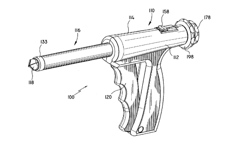
Fig. 1 is a perspective view of one embodiment of a
tissue removing instrument constructed in accordance with
the present disclosure;
Fig. 2 is a perspective view with parts separated,
of the embodiment of Fig. 1;
Fig. 3 is a partial view of the interior distal end
of one handle half-section of the embodiment of Fig. 1;
Fig. 4 is an enlarged view of the area of detail
indicated in Fig. 2;
Fig. 5 is a perspective view, with parts separated,
of the concentrically disposed tool mechanisms of the
embodiment of Fig. l;
CA 02214873 1997-09-09
Fig. 6 is a perspective view, with parts separated,
of the obturator of the embodiment of Fig. 1:
Fig. 7 is an enlarged view of the area of detail
indicated in Fig. 6;
Fig. 8 is a perspective view, with parts separated,
of the elongated tissue coring tube of the embodiment of
Fig. l;
Fig. 9 is a perspective view of the tissue coring
tube of Fig. 8, which shows the reverse side of the
distal end of the tube;
Fig. 10 is a perspective view, with parts separated,
of the cutting wire and support tube of the embodiment of
Fig. l;
Fig. 11 is an enlarged perspective view of the
lS distal end of the cutting wire positioned on the support
tube;
Fig. 12 is a horizontal cross-sectional view of the
embodiment of Fig. l;
Fig. 13 is an enlarged view of the indicated area of
detail of the distal end of the instrument shown in
Fig. 12;
Fig. 14 is an initial view showing the embodiment of
Fig. 1 in use;
Fig. 15 is a further view, similar to Fig. 14,
showing the embodiment of Fig. 1 in use;
CA 022l4873 l997-09-09
-16-
Fig. 16 is a horizontal cross-sectional view of the
embodiment Fig. 1 with the obturator removed therefrom;
Fig. 17 is an enlarged view of the area of detail
indicated in Fig. 16;
Fig. 18 is a cross-sectional view taken along
section line 18-18 of Fig. 16;
Fig. 19 is a view, similar to Fig. 18, showing
operational features of the instrument;
Fig. 20 is a cross-sectional view of the proximal
end of the embodiment of Fig. 1, showing the lockout
lever in the locked position;
Fig. 21 is a view, similar to Fig. 20, showing the
lockout lever in the released position;
Fig. 22 is a view, similar to Fig. 17, showing the
movement of the central elongated tube;
Fig. 23 is a further view, similar to Fig. 14,
showing the embodiment of Fig. 1 in use;
Fig. 24 is a view of the distal end of the
embodiment of Fig. 1 inserted around target tissue;
Fig. 25 is a view, similar to Fig. 24, showing
deployment of the cutting loop of wire and retaining
strap;
Fig. 26 is a horizontal cross-sectional view showing
the proximal end of the instrument during operation of
the trigger;
CA 02214873 1997-09-09
Fig. 27 is a view, similar to Figs. 24 and 25,
showing complete deployment of the cutting loop of wire
and retaining strap;
Fig. 28 is a perspective view of a further
embodiment constructed in accordance with the present
disclosure and mounted on a cooperative portion of a
stereotactic imaging machine;
Fig. 29 is a longitudinal cross-sectional view from
the top of the embodiment of Fig. 28;
Fig. 30 is a perspective view, with parts separated,
of the components contained in the housing or handle
portion of the embodiment of Fig. 28;
Fig. 31 is a cross-sectional view taken along
section line 31-31 of Fig. 29;
Fig. 32 is a cross-sectional top view of the
proximal end of the embodiment of Fig. 28;
Fig. 33 is a cross-sectional view taken along
section line 33-33 of Fig. 32;
Fig. 34 is a view, similar to Fig. 32, showing the
operation of various elements of the embodiment of Fig.
28;
Fig. 35 is a cross-sectional view taken along
section line 35-35 of Fig. 34;
Fig. 36 is a view demonstrating a sequence of
operation of the embodiment of Fig. 28 as mounted on a
cooperative portion of a stereotactic imaging machine;
CA 02214873 1997-09-09
Fig. 37 is a view, similar to Fig. 36, demonstrating
a further sequence of operation of the embodiment of Fig.
28;
Fig. 38 is a view, similar to Fig. 36, demonstrating
a further sequence of operation of the embodiment of Fig.
28;
Fig. 39 is a view, similar to Fig. 36, demonstrating
a further sequence of operation of the embodiment of Fig.
28;
Fig. 40 is a view, similar to Fig. 36, demonstrating
a further sequence of operation of the embodiment of Fig.
28;
Fig. 41 is a perspective view of a further
embodiment of a tissue removing apparatus constructed in
accordance with the present disclosure;
Fig 42 is a perspective view of a further embodiment
of a tissue removing apparatus constructed in accordance
with the present disclosure;
Fig. 43 is a side elevational view of the embodiment
of Fig. 42;
Fig. 44 is a cross-sectional view taken along
section line 44-44 of Fig. 43;
Fig. 45 is perspective view of a rack assembly for
manually effectuating rotation of a portion of a tissue
removing apparatus;
CA 02214873 1997-09-09
-19-
Fig. 46 is a top view of the rack assembly shown in
Fig. 45;
Fig. 47 is a side elevational view of a further
alternative embodiment tissue removing apparatus;
Fig. 48 is a cross-sectional view taken along
section line 48-48 of Fig. 47;
Fig. 49 is a side elevational view of a further
alternative embodiment tissue removing apparatus;
Fig. 50 is a cross-sectional view taken along
section line 50-50 of Fig. 49;
Fig. 51 is a partial perspective view of one
embodiment of the tissue sampling and/or removal system
of the present disclosure;
Fig. 52 is a top view of one embodiment of the drive
mechanism for the tissue sampling/removal system of the
present disclosure; and
Fig. 53 is a side view of an alternative embodiment
of the drive mechanism of Fig. 52.
DETAI~ED DESCRIPTION OF PREFERRED EMBODIMENTS
Referring initially to Figs. 1-5, one embodiment of
an instrument for removing and/or taking a biopsy of
tissue in accordance with the present disclosure is
designated by reference numeral 100 throughout the
several views. The instrument 100 is particularly
adapted for minimally invasive insertion into tissue
CA 02214873 1997-09-09
-20-
immediately adjacent the target tissue, and then for
coring out and removing the target tissue from the
patient. It will be understood by those skilled in the
art, however, that the embodiments of the tissue removing
instrument described herein, although generally directed
to removal of breast tissue, may also be utilized for
removal and/or biopsy of target tissue from other areas
of a patient's body as well.
Generally, instrument 100 includes a housing such as
body portion 110 (formed from handle half-sections 112
and 114), and an elongated tubular body portion 116. A
penetrating member, such as obturator 118 extends through
a longitudinal passageway of instrument 100 and extends
out the distal end. An actuator, for example trigger 120
is preferably pivotally mounted in an opening formed
between handle half-sections 112 and 114. Except where
noted otherwise, the materials utilized in the components
of the instrument generally include such materials as
polycarbonate for housing sections and related
components, and stainless steel for components which
transmit forces. One preferred polycarbonate material is
available from General Electric under the trade name
LEXAN. It is also preferred that radiolucent materials
be utilized for appropriate instrument components, e.g.,
elongated tubular portions, so as not to interfere with
imaging of tissue positioned adjacent thereto.
CA 02214873 1997-09-09
The relative assembly of the various structural
components of instrument 100 can be readily appreciated
with reference to Figs. 2-13. Referring initially to
Figs. 1 and 2, handle half-sections 112 and 114 are
preferably molded to have predetermined contoured regions
for housing the various components as well as
facilitating the instrument's operation. Each of the
handle half-sections 112 and 114 has a grip portion 122,
in the shape of a pistol grip, which extends generally
transversely away from a longitudinal axis "L" of a
barrel portion formed when handle half-sections 112 and
114 are joined. Opposed semi-cylindrical walls 128 and
130 form a generally cylindrical passageway with adjacent
semi-cylindrical portions, i.e., raised wall portion 136
and semi-annular groove 144, from the proximal end of
body 110 to the distal end thereof. Handle half-sections
112 and 114 may be joined together by any suitable means,
for example, by sonic welding, snap fit, securing
screw(s), adhesive bonding or the like.
Referring to Figs. 4 and 5 in conjunction with Figs.
1 and 2, elongated tubular portion 116 includes a series
of elongated components which are preferably
concentrically disposed with respect to each other. An
outer tubular sheath 132 has a proximal end held securely
between semi-cylindrical walls 128 and 130 and a distal
end which is covered by a collar 133 securely attached
CA 02214873 1997-09-09
-22-
thereto. A pair of transversely extending tab portions
134 are formed at the proximal end of outer tubular
sheath 132 and fit into slots 135 formed at the juncture
of semi-cylindrical walls 128, 130 and raised portions
135. Tab portions 134 bias against raised portions 136
to prevent proximal movement of outer tubular sheath 132
when the instrument 100 is inserted into the body tissue.
A tubular member, such as central tubular shaft 138,
is axially and rotatably movable within outer tubular
sheath 132. The rotation of central tubular shaft 138,
however, may be selectively prevented by a mechanism
described in detail below. Additionally, central tubular
shaft 138 may be temporarily and selectively maintained
in a fixed axial position relative to barrel portion 126
of body 110. This fixed axial re~ationship may be
accomplished, for example, by a cylindrical protrusion
140 (Fig. 9) formed near the proximal end of central
tubular shaft 138 being positioned in an annular groove
formed by closing semi-annular groove portions 142 and
144 formed in handle half-sections 112 and 114,
respectively. In this manner, central tubular shaft 138
may remain fixed axially within body 110 so as to freely
rotate therein but not be removed therefrom.
Obturator 118 is slidably positioned within central
tubular shaft 138 and is preferably designed to cooperate
with central tubular shaft 138 so as to prevent rotation
CA 02214873 1997-09-09
-23-
of both central tubular shaft 138 and obturator 118
during the initial insertion of instrument loo into the
patient. A preferred manner in which to accomplish this
selective fixing of the rotational movement of both
S central tubular shaft 138 and obturator 118 as well as to
prevent relative axial movement of those components with
respect to each other as well as body 110 is best shown
in Figs. 2, 3 and 5.
In particular, a pin 146 is transversely secured in
lo elongated shaft 148 of obturator 118 near its proximal
end. Upon insertion of obturator 118 in central tubular
shaft 138, pin 146 is received in a slot 150 formed in a
collar 152, which is secured to the proximal end of
central tubular shaft 138. This relationship between
obturator 118 and central tubular shaft 138 prevents
relative rotational movement between the two components.
To prevent relative rotational movement between either
obturator 118 or central tubular shaft 138 and body llO,
the subassembly of obturator 118 and central tubular
shaft 138 is secured in body 110 by a bayonet-type mount,
Fig. 3, created by the interaction of pin 146 and a
lockout groove, such as L-shaped groove 154 formed along
the inner wall of handle half-section 112. L-shaped
groove 154 is preferably provided with a lip 156 which
serves to maintain pin 146 in the locked-out position.
CA 02214873 1997-09-09
-24-
Referring once again to Figs. 2 and 4, another
locking mechanism is shown provided on instrument loO to
facilitate selective axial movement of central tubular
shaft 138 once the instrument is inserted around the
S target tissue. Lockout lever 158 is pivotably mounted to
body 110 and is temporarily maintained in the locked-out
position by raised portions 160 extending laterally from
the side surfaces of lockout lever 158 near a proximal
end thereof being seated in detents 162 formed along the
inner surface of handle portions of 112 and 114,
respectively, at a position proximal of the groove formed
by semi-annular groove portions 142 and 144. The
operational aspects of lever lockout 158 will be
explained in further detail herein.
Trigger 120 is preferably pivotably attached to body
110 in recessed portions 164 and 166 formed in the handle
half-sections 112 and 114. Trigger 120 is connected to a
tissue cutting member, e.g., a filament or wire, such as
wire 168, by a pin extending through a throughbore formed
near the top of trigger 120 (Fig. 16). Wire 168 is
maintained in a preferred orientation by an elongated
tubular sheath 170 which is preferably concentrically
disposed within outer tubular sheath 132 such that
laterally extending tab portions 172 are situated
adjacent tab portions 134 and maintained between housing
handle half-sections 112 and 114 as described above for
CA 02214873 1997-09-09
outer tubular sheath 132. A longitudinal slot 174 is
formed beginning at the proximal end of outer tubular
sheath 132 and is disposed between laterally extending
tab portions 134 so as to receive wire 168 and permit
movement of the wire loop with respect to outer tubular
sheath 132.
Referring now to Figs. 6-13, the various structural
subassemblies will now be described individually. As
shown in Figs. 6 and 7, obturator 118 includes elongated
shaft 148, a cutting head 176 secured to a distal end of
the shaft and a knob 178 attached to a proximal end of
the shaft to facilitate insertion and removal of the
obturator 118 from the instrument 100. Cutting head 176
is preferably provided with slots 180 and 182, formed
orthogonally with respect to each other and which are
dimensioned to receive individual blades 184 such that a
cutting edge 186 formed on each blade 184 is angled to
correspond to the angled distal surfaces 188 of the
cutting head 176.
To facilitate assembly of the cutting head 176,
individual blades 134 are each provided with a
transversely extending slot 188 having a series of
individual tooth members 190 extending from the side wall
of the slot. Teeth 190 are preferably formed in the
shape of a ramp-shaped camming surface to interlock with
complimentary surfaces (not shown) formed within
CA 02214873 1997-09-09
-26-
orthogonally disposed slots 180 and 182. Cutting head
176 is in the shape of a plug member having a proximally
extending portion 192 of reduced diameter which is
inserted into a bore 194 formed at the distal end of
obturator 118 so as to be fixedly secured thereto. Any
suitable known techniques for mounting may be utilized,
such as friction fitting, bonding, adhesives or the like.
As shown in Figs. 8 and 9, central tubular shaft 138
has a tissue cutting surface, such as annular cutting
edge 196 formed at the distal end to facilitate coring of
the tissue surrounding and including the target tissue
within the patient. The shaft is preferably formed of a
material suitable for forming a sharpened edge, such as,
for example, stainless steel. A knob 198 is secured to
the proximal end of central tubular shaft 138, for
example, by locking tabs 200 engaging cut out portions
202 formed in cylindrical section 152 of knob 198. Knob
198 is preferably further provided with a knurled
gripping surface 206 to facilitate rotation of the shaft
during the coring action of the tissue. Such rotational
movement is facilitated by the disposition of pin 140
within the annular groove formed by semi-annular groove
portions 142 and 144, as noted above.
In Figs. 10 and 11, the cutting assembly including
2s wire 168 and elongated tubular sheath 170 are shown in
detail. As will be described later herein, wire 168
CA 02214873 1997-09-09
-27-
facilitates the severing of the tissue core to permit
removal of the targeted tissue from the patient and,
optionally, delivers electrocautery current to the tissue
as cutting is accomplished. Wire 168 is preferably
S formed of a single length of thin gauge, stainless steel
wire which is bent to an initial configuration or pre-
fired condition contained within instrument 100, as shown
in Fig. 10.
Initially, wire 168 is folded in half such that free
ends 208 and 210 are positioned at the proximal end and
are formed into a U-shaped bend to hook around pin 212
disposed at the top of trigger 120 (Figs. 2 and 17).
Wire 168 extends longitudinally along the outer surface
of elongated tubular sheath 170 to the distal end
thereof. A circular loop 213 is formed at the distal end
of wire 168 and is positioned adjacent a flange 214
formed at the distal end of the tubular sheath 170.
Flange 214 is provided with radially extending leg
portions 218 which form diametrically opposed passageways
which hold wire 168 in a position substantially aligned
with the distal end of tubular sheath 170. A tissue
retaining member, such as strap 216, is wrapped around
circular loop 213 and is provided with a tabbed end
portion 220 to maintain the positioning of the strap
across the distal opening of elongated tubular sheath
CA 02214873 1997-09-09
-28-
upon cutting of the tissue core, which will explained in
greater detail herein.
The relative positioning of the various structural
subassemblies in the initial configuration of instrument
S 100 is shown in the longitudinal cross-sectional view of
Fig. 12. In particular, obturator 118 is shown inserted
in instrument lOO with lockout lever 158 preventing
proximal movement of central tubular shaft 138. As best
seen in the greatly enlarged view of Fig. 13, wire 168 is
maintained in position by central tubular shaft 138 and
obturator 118 on the interior side and by collar 133 on
the exterior side. Wire 168 cannot be deployed to cut
tissue until both obturator 118 and central tubular shaft
138 are moved distally of loop 213 (Fig. 10).
A preferred method of using instrument 100 is
illustrated in Figs. 14-27. Instrument 100 is inserted
into the breast tissue along a predetermined path toward
the target tissue 222. The location of the target tissue
can be specifically determined through the use of known
localization techniques, such as for example, the
insertion of a localization needle and/or the use of a
stereotactic mammography device. Thus, for example, the
target tissue may be tagged with a tagging device and
instrument 100 moved adjacent the tagged location under
conventional imaging guidance, or instrument 100 may be
adapted to move along a target tissue locating device,
CA 02214873 1997-09-09
-29-
such as a conventional K-wire, which was pre-positioned
adjacent or across the target tissue. Instrument lOO may
cooperate with a target tissue locating device in a
variety of manners such as sliding coaxially along such
locating device.
Once instrument 100 is inserted to a position
immediately adjacent the target tissue, obturator 118 is
first rotated in a counterclockwise fashion as indicated
by arrow "A" in Fig. 14, by the user gripping knob 178
and rotating the knob in a counterclockwise fashion.
This rotational movement disengages pin 146 from L-shaped
groove 154 (Figs. 3 and 6) to permit axial movement of
obturator 118 relative to the instrument 100. In
particular, obturator 118 may be removed from the
instrument 100 by pulling on knob 178 in a proximal
direction as indicated by arrow "B" in Fig. 14.
With the obturator 118 removed, the target tissue is
cored out from the surrounding tissue by urging
instrument 100 in a proximal direction as indicated by
arrow "C" in Fig. 15, while simultaneously turning knob
198 of central tubular shaft 138 to cause rotation of
annular cutting edge 196 at the distal end of the central
tubular shaft 138. Rotation of the elongated central
tubular shaft 138 may be in either a clockwise or
counterclockwise direction or both depending on the
CA 02214873 1997-09-09
-30-
preference of the user, as indicated by arrow "D" in Fig.
15.
When the target tissue is completely within the
distal end of instrument 100, central tubular shaft 138
is moved proximally to allow for deployment of wire loop
168 to sever the tissue core from the patient.
Electrocautery current is optionally delivered to the
tissue by wire loop 168 as severing is accomplished. As
shown in Figs. 16 and 17, elongated central tubular shaft
138 is shown extending distally from the distal end of
instrument 100 and preventing wire loop 168 from moving
out of alignment with the circumferential alignment with
the distal end of elongated tubular sheath 170.
Fig. 18 shows the relative positioning of pin 140
within annular groove 141 to facilitate the rotation of
elongated central tubular shaft 138 therein. Such
rotation is possible when the obturator 118 is removed
from instrument 100. When the tissue core is of
sufficient depth, knob 198 is rotated, as indicated by
arrow "E" in Fig. 19, to align pin 140 with a keyway 224
formed in handle half-sections 112 and 114. This
alignment permits proximal movement of central tubular
shaft 138 when lever lockout 158 is pushed down, as
indicated by arrow "F" in Fig. 21, to release protrusion
160 from detent 162 (Figs. 2 and 4). Knob 198 is pulled
proximally as indicated by arrow "G" in Fig. 21 to move
CA 02214873 1997-09-09
-31-
the distal end of central tubular shaft 138 proximal of
wire loop 213.
With central tubular shaft moved proximal of wire
loop 213, transverse movement of the wire loop across the
distal open end of elongated tubular sheath 170 is
effected by squeezing trigger 120, as indicated by arrow
"H" in Fig. 25. Upon transverse movement of wire loop
168, strap 216 is pulled distally in the direction
indicated by arrow "I" in Fig. 25. With further
squeezing of trigger 120, strap 214 is pulled completely
across the opening at the distal end of elongated tubular
sheath 170 so that tab portion 220 is prevented from
further distal movement by leg portions 218 and strap 214
is pulled taut across the distal end opening of elongated
tubular sheath 170. Instrument 100 may thus be removed
from the patient's breast. Due to the partial
obstruction of the distal end opening of elongated
tubular sheath 170 by strap 214, the severed tissue core
will be removed from the patient with instrument 100. To
the extent necessary, the puncture wound left by
instrument 100 may be closed by any suitable known
suturing techniques.
Another embodiment of the presently disclosed
instrument for removing and/or taking a biopsy of target
tissue and a method of its use are illustrated in Figs.
28-40. Referring initially to Figs. 28-30, instrument
CA 022148i3 1997-09-09
-32-
300 is particularly adapted for use on a precision
instrument positioning machine, for example, a
stereotactic imaging machine. Such devices are
commercially available, for example, from Lorad
Corporation of Danbury, Connecticut. An example of such
a machine is disclosed in U.S. Patent No. 5,289,520 which
issued February 22, 1994 to Pellegrino et al., the
contents of which are hereby incorporated by reference.
Briefly, stereotactic machines facilitate stereo x-
ray imaging of a patient's bréast using a three
dimensional coordinate system, while the patient is in a
prone position on a specially designed table. An opening
is provided on the table to permit the patient's breast
to be pendulantly disposed therethrough and a clamp is
used to fix the exact location of the patient's pendulant
breast relative to the operational components of the
machine which facilitate precision interaction of
instrumentation with the breast, i.e. for biopsy or
tissue removal.
The overall structural and operational features of
instrument 300 are very similar to those described above
for instrument 100. Accordingly, the following
description will focus on those features which are either
unique to instrument 300 or are substantially different
than corresponding elements of instrument 100. In Fig.
28, instrument 300 is shown mounted in place on the
CA 02214873 1997-09-09
-33-
instrument positioning control mechanism of a
stereotactic machine, generally designated by reference
numeral 302. Stereotactic machine 302 has an instrument
mount 304, the movement of which is coordinated with the
S imaging capabilities of the machine. The instrument
mount 304 is provided with a standardized instrument or
tool mounting bracket 305 to facilitate mounting of
various surgical instruments which can take advantage of
the precision positioning features of the stereotactic
machine. This is particularly beneficial in procedures
where the target tissue is not palpable. As will be
readily apparent based on the disclosure herein, the
cooperative structures on instrument 300 and stereotactic
machine 302 may be reconfigured so that more structure is
included on instrument 300 and less on machine 302, or
vice versa. All that is required is that stereotactic
machine 302 and instrument 300 cooperate so as to
position instrument 300 as desired with respect to the
target tissue.
Instrument 300 is provided with four slide mounts
306, two of which are formed on each side of housing
half-sections 312 and 314 so that instrument 300 can be
mounted on either side. Thus, the mechanical operational
controls of instrument 300, all of which are positioned
on the same side of the instrument, may be oriented to
suit the preference of the personnel using the instrument
CA 02214873 1997-09-09
-34-
during the particular procedure. It is envisioned that
some of the control actuators of instrument 300 may be
reconfigured so that they would be operable from a
different side than the remaining control actuators.
Housing half-sections 312 and 314 are preferably molded
to conform to the dimensions of the stereotactic machine
tool mounting bracket 305, for example, a rectangular
base dimension.
Obturator 318 has a pair of resiliently formed
retaining members 319 each of which include a shoulder
portion 321 which engages a cut-out portion of the
proximal end wall of housing half-section 314 to maintain
obturator 318 in place during insertion of instrument
300.
As shown in Figs. 29-31, a firing lockout mechanism
is provided to prevent premature movement of the cutting
wire before obturator 318 and central tubular shaft 338
are properly positioned relative to the wire loop
positioned at the distal end of wire 368 (similar to loop
213 of wire 168). The firing lockout mechanism includes
a safety lockout member 323 and a control member, such as
slide bar member 341. Lockout member 323 is slidably
received in a cutout 325 formed in a sidewall of housing
half-section 314 and has a pair of slotted keyways 327
and 329 formed thereon. Also provided on lockout member
323 are raised portions 331 which provide tactile
CA 02214873 1997-09-09
-35-
indication to the user of the relative positioning of
lockout member 323 during a two-stage lockout release
process described below.
Trigger 320 is provided with a retaining pin 333
which has a pair of bores formed therethrough to receive
and frictionally retain wire loop 368. A latch portion
335 is formed extending from the distal side of trigger
320 which is configured and dimensioned to interact with
lockout member 323 and specifically to slide in keyway
lo 327.
Central tubular shaft 338 is fitted at a proximal
end with gear collar 337, the teeth of which are designed
to mesh with the teeth of gear 339 which is manually
driven by a drive mechanism. A preferred manual drive
mechanism 700 is depicted in FIGS. 45 and 46 and includes
a mounting body 702 which is adapted to be mounted to a
stereotactic imaging apparatus by way of mounting
- apertures 704. A rack 706 is movably mounted to mounting
body 702 and includes a plurality of teeth 708 and a pair
of elbow handles 710, 712 at either end thereof.
Inclined faces 714 on rack 706 cooperate with abutment
faces 716 and overhang 718 on mounting body 702 to mount
rack 706 with respect to mounting body 702. Transverse
movement of rack 706 with respect to mounting body 702 is
limited by stops 722, 724 formed on rack 706. The size
and spacing of teeth 708 are selected to cooperate with
CA 02214873 1997-09-09
-36-
the teeth of gear 339. The number of teeth 708 on rack
706 are selected to effectuate the degree of rotation of
gear 339 desired, e.g., 90Q, 180Q, 360Q, etc. Thus,
transverse movement of rack 706 effectuates rotational
movement of gear 339 and concomitant rotation of tubular
shaft 338. Alternatively, a powered drive mechanism may
be provided on stereotactic machine 302.
A slide bar 341 cradles gear collar 337 to permit
rotational movement thereof while controlling the axial
alignment of central tubular shaft 338 within housing
half-sections 312 and 314. Slide bar 341 is provided
with a latch portion 343 formed at a proximal end
thereof. At the distal end, slide bar 341 has actuator
button 345 to facilitate proximal movement of slide bar
341 by the user. Another feature of slide bar 341 is a
diagonal groove 347 which is formed in the side surface
adjacent the proximal end of the slide bar to permit wire
loop 368 to slidably pass therethrough, as best seen in
Fig. 29.
The two stage lockout process of lockout member 323
is best shown in Figs. 31-35 in conjunction with Figs.
36-40. Upon the insertion of the instrument into the
patient, Figs. 36 and 37, it is desirable to maintain the
relative axial positioning of central tubular shaft 338
with respect to outer tubular sheath 332 as well as to
prevent firing of trigger 320. Both of these preventive
CA 02214873 1997-09-09
-37-
goals are accomplished when obturator 318 is positioned
within the instrument and lockout member 323 is
maintained in its initial position as shown in Fig. 29 by
obturator member 318 and shoulder portion 349 of lockout
member 323 biasing against the outer wall of housing
half-section 314. In this position, keyways 327 and 329
of lockout member 323 are maintained out of alignment
with slide bar 341 and latch portion 335 of trigger 320,
respectively.
After insertion of instrument 300 into the patient
as shown in Fig. 37, preferably by automated movement of
instrument mount 304 by a drive mechanism on stereotactic
machine 300, obturator 318 is removed (Figs. 29 and 38)
by pressing radially inwardly on retaining members 319 to
disengage the retaining members from shoulder portions
321 from the proximal end wall of housing half-section
314. With obturator 318 removed from the instrument, as
shown in Fig. 32, lockout member 323 is free to move
transversely toward the central longitudinal axis of
instrument 300.
The first stage of releasing lockout member 323,
illustrated in Fig. 32, is accomplished when the user
pushes lockout member 323 inwardly toward the center of
the instrument. A tactile indication is felt by the
user when the first raised portion 331 passes over the
side wall of housing half-section 314. Actuator button
CA 02214873 1997-09-09
-38-
345 is moved proximally, as indicated by arrow "J" in
Fig. 32, to effect proximal movement of central tubular
shaft 138. This proximal movement is limited by
partition 351 formed transversely across housing half-
section 314. During proximal movement of slide bar 341,latch portion passes through keyway 327 and prevents
further transverse movement of lockout member 323 until
latch portion 343 passes completely through keyway 327.
After proximal movement of central tubular shaft 38,
lockout member 323 is again pushed transversely inward
(see Figs. 32 and 33) until the user feels another
tactile indication, resulting from the second raised
portion 331 crossing over the side wall of housing half-
section 314. In this position, as shown in Figs. 34 and
lS 35, latch 335 of trigger 320 is aligned with keyway 329.
Trigger 320 is moved proximally in the direction of arrow
"K". Also when lockout member 323 is in the orientation
shown in Fig. 34, latch portion 343 of slide bar 34~ is
in engagement with lockout member 323 to prevent distal
movement of slide bar 341 and, therefore, central tubular
shaft 338, during firing of trigger 320.
A further embodiment of a tissue removing instrument
is shown in Fig. 41. Instrument 400 is similar to the
embodiment of Figs. 28-40 and is designed to be inserted
and used manually by a surgeon, rather than in
conjunction with a stereotactic machine. The handle of
CA 02214873 1997-09-09
-39-
instrument 400 includes handle half-sections 412 and 414
which are molded to a dimension suitable for being held
in the palm of either the user's left or right hands.
The control mechanisms of instrument 400 may be the same
S as those for instrument 300 or lockout member 323 may be
eliminated as shown in Fig. 41. The basic manner of
usage of instrument is the same as that for instrument
300.
Another embodiment of the apparatus for removing
- lO tissue constructed in accordance with the present
disclosure is illustrated in Figs. 42-44 as instrument
500. The overall structural and operational features of
instrument 500 are very similar to those described above
for instrument 300. For example, a wire loop similar to
wire loop 368 of instrument 300 is also utilized to sever
the tissue enclosed by instrument 500 in the same manner
as in instrument 300, optionally with cautery. For
clarity in illustrating and describing the alternative
features of instrument 500, however, the wire loop is not
shown. It is to be understood, however, that the wire
loop of instrument 500 is fully incorporated in
instrument 500 and performs the same function(s) of wire
loop 368 in instrument 300 in the same manner.
Accordingly, the following description will focus on
those features which are either unique to instrument 500
or are substantially different than corresponding
CA 02214873 1997-09-09
-40-
elements of instrument 300. Instrument 500 is designed
to be mounted on a stereotactic machine in the same
manner as instrument 300. However, rather than a
piercing obturator, such as obturator 318 (Fig. 29),
instrument 500 is provided with a blunt obturator 518
that is preferably formed of a two part polycarbonate
housing having half-sections 518a and 518b. The half-
sections 518a and 518b are advantageous in that they
facilitate assembling blunt obturator 518 around a
surgical instrument, preferably an instrument designed
for use in minimally invasive procedures, for example,
elongated biopsy tissue marker 601. Thus, surgeons may
take advantage of the precision positioning capabilities
of a stereotactic imaging apparatus to precisely insert
and bring the working components of such minimally
invasive instruments to precise locations to conduct the
desired procedure. It will be understood by those
skilled in the art that different blunt obturators may be
configured and dimensioned to receive a variety of
instruments, thereby mating such instrumentation with
instrument 500.
As shown in Fig. 44, blunt obturator 518 preferably
includes a distal end surface 519 which is planar and
includes a central aperture to facilitate the passage of
the distal end of a particular instrument inserted
therethrough, e.g., distal end 603 of biopsy tissue
CA 02214873 1997-09-09
-41-
marker 601. Blunt obturator 518 is further provided with
a series of alignment portions which are preferably a
series of spaced apart, axially aligned supports 525
formed along the inner surface of blunt dilator 518.
Supports 525 advantageously facilitate maintaining the
axial alignment of an instrument, e.g. instrument 601,
inserted through blunt obturator 518 by defining a
longitudinal passageway through blunt obturator 518.
Preferably, the longitudinal channel defined by supports
525 is coaxially aligned with a longitudinal channel
defined by instrument 500 housing half-sections 512 and
514.
A locking mechanism is also provided which
facilitates blunt obturator 518 being fixedly retained in
lS instrument 500 during movement of instrument 500 during
portions of the surgical procedure. As noted above, one
advantage of maintaining obturator 518 in place relative
to instrument 500 is to precisely introduce an instrument
disposed in obturator 518 into the patient with
instrument 500. A further advantage of maintaining blunt
obturator 518 in place during insertion of instrument 500
into the tissue of the patient, e.g. into the breast
tissue of a female patient in a breast biopsy procedure,
is that annular cutting edge 596, located at the distal
end of central tubular shaft 538, is prevented from
CA 02214873 1997-09-09
-42-
coring tissue which is not intended to be cored by
instrument 500.
The locking mechanism includes retainer clips 519
formed on collar 583. Retainer clips 519 are preferably
flexible such that upon insertion of obturator 518 into
an opening formed on the proximal end wall formed by
housing half-sections 512 and 514, a shoulder portion
similar to shoulder portion 321 of retaining members 319
(Fig. 29) engages the inner surface of the proximal end
wall of instrument 500.
A mounting tube 585 may be provided, as necessary,
to facilitate mounting particular surgical instruments,
such as instrument 601, to blunt obturator 518. As shown
in Fig. 44, mounting tube 585 has notches 587 formed
adjacent a distal end to facilitate a snap fit into an
aperture defined by housing half-sections 518a and 518b.
Instrument 601 may be attached to mounting tube 585 by
any suitable known mounting structure or technique, for
example, a quick connect mechanism, snap fit, fasteners,
or the like.
Slide bar 541 serves to retract central tubular
shaft 538 in a manner similar to slide bar 341 of
instrument 300 (Fig. 30) and includes actuator grips 545
positioned at the distal end of instrument 500 adjacent
fixed handle 521. In this manner, once the tissue
enclosed by instrument 500 is ready to be cut, central
CA 02214873 1997-09-09
-43-
tubular shaft 538 is retracted by pulling grips 545 to
expose the wire loop cutting member (as shown in Fig. 22
for instrument lO0).
Further alternative obturator structures are
S contemplated for use with the tissue removal apparatus
disclosed herein. For example, two contemplated
obturator embodiments are depicted in Figs. 47, 48 and in
Figs. 49, 50, respectively. In the embodiment of Figs.
47, 48, an instrument is provided which includes a
plurality of telescoping dilators which may be
sequentially advanced from the distal end of the
elongated body portion to dilate tissue in a step-like or
gradual manner. In the embodiment of Figs. 449, 50, an
instrument is provided which includes an inflatable
dilating structure.
More particularly, instrument 800 of Figs. 47 and 48
includes a first dilating structure 850, a second
dilating structure 852, and a third dilating structure
854. Each of such dilating structures 850, 852, 854
define a central aperture 850a, 852a, 854a, respectively,
of increasing diameter. Thus, the diameter of aperture
850a is such that it receives an instrument, e.g.
instrument 603, therethrough and advantageously maintains
axial alignment therewith. Aperture 852a in turn is
sized to receive first dilating structure 850
therethrough, and aperture 854a is sized to receive
CA 02214873 1997-09-09
-44-
second dilating structure 852 therethrough. In this way,
first, second and third dilating structures 850, 852, 854
define telescoping members which gradually increase the
degree to which tissue is dilated. Each dilating member
includes a conical face at its distal end (e.g., conical
face 850b) to effectuate tissue dilation, although other
geometries are also contemplated, e.g., pyramidal, and
may also be utilized to effectuate dilation.
At the proximal end of instrument 800, first
dilating structure 850 defines a barrel extension 850b
and a flange 850c. Flange 850c is sized to abut flange
852c formed at the proximal end of second dilating
structure 852 and flange 852c is sized to abut flange
854c formed at the proximal end of third dilating
structure 854. Thus, in use, the surgeon would first
advance first dilating structure distally relative to
second dilating structure 852, thereby bringing flange
850c into abutment with flange 852c. This distal
movement also advances the conical face at the distal end
of first dilating structure from elongated tube 816 and
effectuates a degree of tissue dilation. Thereafter,
both flange 850c and flange 852c are advanced distally
until flange 852c abuts flange 854c. This movement
effects distal movement of the conical face at the distal
end of second dilating structure 852 and effectuates
further tissue dilation. The conical faces of respective
CA 02214873 1997-09-09
-45-
dilating structures register with each other such that a
substantially continuous conical face is formed as
respective dilating structures are distally advanced.
Finally, third dilating structure 854 is distally
advanced, thereby further dilating tissue, until flange
854c abuts stop 856.
As will be readily apparent, greater or lesser
numbers of dilating structures may be employed to
effectuate the desired tissue dilation. In addition, the
angle of the conical face may be varied to effect
different rates and resistances to dilation.
A further alternate obturator embodiment is depicted
by instrument 900 in Figs. 49 and 50. Instrument 900
includes a fluid conduit 950 at its proximal end which is
preferably opened and closed by a valve mechanism (not
shown), e.g., a stopcock. Fluid conduit 950 communicates
with an axial fluid passage 952 which extends distally
into an inflatable balloon 954 positioned at a distal end
of a hollow rod 956 which receives a surgical instrument,
e.g., instrument 603, and is movably mounted with respect
to elongated tube 916. Balloon 954 is adhered to rod 956
such that the introduction of an inflationary fluid,
e.g., saline, does not cause separation of balloon 954
therefrom. Suitable adhesives as are known in the art
are generally employed for this purpose. Although
balloon 954 is shown inflated within elongated tube 916,
CA 02214873 1997-09-09
-46-
it is contemplated that in use balloon 954 would remain
non-inflated until advanced distally from elongated tube
916 into tissue. A stabilizing disk 958 is provided on
rod 956 and advantageously maintains rod 956 in axial
alignment with elongated tube 916. A stop 960 interacts
with the body 962 of the valve mechanism to limit distal
movement of rod 956, and thus balloon 954.
In use, knife 938 is initially withdrawn and body
962 is advanced distally relative to elongated body 916,
thereby advancing balloon 954 from within elongated body
916. Inflating fluid, e.g., saline or air, is introduced
through fluid conduit 950, fluid passage 952 and into
balloon 954. Balloon 954 is thus inflated and
effectuates tissue dilation in a controlled and
atraumatic manner. Thereafter, balloon 954 is deflated,
e.g., by reversing the syringe action, and withdrawn into
elongated tube 916. The procedure may then proceed as
discussed hereinabove.
Referring now to Figs. 51 and 52, the powered drive
mechanism for the tissue sampling/removing system of the
present disclosure will now be addressed in detail. As
noted above in connection with the embodiment of Fig. 15,
rotation of the elongated central tubular shaft 138 may
be in either a clockwise or counterclockwise direction,
or both, depending on the preference of the user, as
indicated by arrow "D" (Fig. 15). Further, as previously
CA 02214873 1997-09-09
-47-
noted in connection with the description of the
embodiment as shown in Figs. 28-40, central tubular shaft
338 is fitted with a proximal end gear collar 337 for
interaction with a drive mechanism which, as noted, may
be a powered drive mechanism.
A system for removing and/or taking a biopsy of
target tissue, shown as system 1000 in Fig. 51,
incorporates the previously noted powered drive mechanism
to effectuate the bi-directional rotation of the tubular
cutting shaft 1038. System 1000 includes a tissue
imaging device which includes an instrument guidance and
positioning device, for example, a stereotactic imaging
positioning device 1039, such as the LORAD~ STEREOGUIDE
breast biopsy system available from LORAD, Danbury
Connecticut, instrument mounting stage 1005 which
preferably houses the powered drive mechanism, and tissue
removal instrument 1100. Tissue removal instrument 1100
is similar to instruments 800 and 900 and the tissue
removal instrument disclosed in commonly assigned, co-
pending U.S. Application Serial No. 08/665,176, filed onJune 14, 1996 by Milliman et al., the entire contents of
which are hereby incorporated by reference. The general
structure and operational details of the imaging device
1039 are disclosed in U.S. Patent No. 5,289,520 which
issued February 22, 1994 to Pellegrino et al., the entire
contents of which are hereby incorporated by reference.
CA 02214873 1997-09-09
-48-
Briefly, stereotactic machines facilitate stereo x-
ray imaging of a patientls breast using a three
dimensional coordinate system while the patient is in a
prone position on a table having an aperture to permit
the subject breast to be pendulantly disposed through the
aperture relative to the rest of the body. A compression
paddle having a window formed therein is used to hold the
pendulant breast in a precise location relative to the
operational components of the machine. Precision
interaction of the instrumentation with the breast is
thus facilitated, e.g., for localization and tissue
removal.
Referring to Fig. 52 one embodiment of the drive
mechanism of the present disclosure is shown as drive
mechanism 1110 as it is operatively associated with
instrument 1100. Drive mechanism 1110 includes motor
1041 which is preferably a stepper type motor such as the
DC MicroMotors Series 1331 available from MicroMo~
MOTORS. Preferably the motor has a constant speed output
of about 10,000 to 13,000 rpm. The motor is preset to
reverse direction of rotation at fractions of a complete
revolution depending upon the size of the coring cannula
being used on the instrument 1100. For example, when
using a 20mm coring cannula the motor 1041 is set to
reverse direction every 6/10 of a revolution. Whereas,
when using a 10mm coring cannula, it has been found to be
CA 02214873 1997-09-09
-49-
effective to set the motor to reverse direction every 1.2
revolutions. Additionally, when using a 5mm coring
cannula, an effective setting for the motor has been
found to be 2.4 revolutions prior to reversing the
direction of the rotation. Of course, variables
associated with the overall system may impact upon the
optimal pre-reversal number of revolutions, e.g., the
sharpness of the cutting surface, characteristics of the
cutting surface, toughness of the tissue, etc.
Another feature of the motor that may be provided is
a kickout switch which will cause the motor to stop if
the instrument is advanced too rapidly into the tissue
being cut. Operation of the motor is preferably
controlled by a conventional foot pedal (not shown) which
is electrically connected to the motor. Thus, the user
can have both hands free to use for other purposes during
the procedure. The motor is electrically connected to a
power source by way of electrical cord 1043 which may be
connected directly to the power supply of the imaging
system 1039 or may be connected to an independent power
supply.
Motor 1041 has a spindle 1045 which rotates
preferably at a constant rate but reverses direction
according to a pre-selected rate as noted above. Gear
1047 is mounted to spindle 1045 and meshes with gear 1049
to which a shaft 1051 is securely attached. Shaft 1051
CA 02214873 1997-09-09
-50-
is positioned parallel to motor 1041 and passes through
an opening formed in the distal end wall of stage 1005
and is positioned in parallel longitudinal alignment with
the central longitudinal axis of coring cannula 1038. A
gear 1053 which may be supplied in the same packaging as
instrument 1100, is fitted on spindle 1051 and maintained
in place by, for example, friction. In this manner, when
instrument 1100 is mounted on stage 1005, teeth 1037 of
coring cannula 1038 will mesh with the teeth of gear 1053
to facilitate transmission of the rotational forces
produced by motor 1041 to coring cannula 1038.
Referring to Fig. 53, an alternative embodiment of
the drive mechanism of the present disclosure is shown
therein as drive mechanism 2110. Drive mechanism 2110
utilizes the same motor 1041 as drive mechanism 1110
except that the spindle 1045 itself passes directly
through the opening formed in the distal end wall of
instrument stage 1005. Drive mechanism 2110 therefore
eliminates the additional gear and shaft utilized in
drive mechanism 1110. Depending on the spatial
requirements for stage 1005 or alignment of gear 1053
with the teeth 1037 of coring cannula 1038, either one of
drive mechanism lllo or 2110 may be utilized.
In use, the instrument 1100 is mounted on the stage
1005 which is securely mounted to the instrument
positioning and guidance device 1039. Stage 1005 is
CA 02214873 1997-09-09
preferably provided with hooks which fit into
corresponding openings formed on the housing of
instrument 1100 so that instrument llOo may be positioned
on the hooks and pulled so that the hooks engage the
instrument housing and securely hold the instrument in
place. This mounting arrangement is described in detail
in the related application Serial No. 08/665,176 filed on
June 14, 1996 by Milliman et al. (hereinafter, ''the '176
Milliman application"), the entire contents of which are
hereby incorporated by reference.
After imaging and localization of the target tissue
is accomplished as described in the '176 Milliman
application, the surgeon effectuates coring of the target
tissue by advancing the instrument 1100 toward the
pendulant breast and activating the bi-directional
rotation of the coring cannula 1038 by depressing the
foot pedal controller (not shown). The remainder of the
operational procedure is substantially the same as
described in the '176 Milliman application.
It will be understood that various modifications may
be made to the embodiments disclosed herein. Therefore,
the above description should not be construed as
limiting, but merely as exemplifications of preferred
embodiments. Those skilled in the art will envision
other modifications within the scope and spirit of the
claims appended hereto.