Note: Descriptions are shown in the official language in which they were submitted.
CA 0221~241 1997-09-11
WO 96/28753 PCT/US96/02772
COMPACT NIGHT VISION DEVICE
TECHNICAL FIELD OF THE INVENTION
The present invention relates to monocular night vision
devices that enable a viewer to observe objects at night or during other
low-light conditions. More particularly, the present invention relates to a
lightweight, low cost monocular night vision system that can be used
independently or can be adapted to be used as an objective lens
supplement or an ocular lens supplement for secondary optical devices,
thereby providing night vision capabilities to such devices.
BACKGROUND ART
Night vision devices are widely used in the military to provide
soldiers, aviators and sailors with the ability to view objects at night or
during other low light conditions. As a result, many night vision devices
are currently being m~nnf~ctured according to exacting military
specifications and designs. Similarly, many such night vision devices are
being manufactured for specific military applications such as part of the
sights of various weapons or as part of goggle assemblies that attach to an
aviator's or soldier's helmet. As a consequence, many of the night vision
devices currently being m~nllf~ctured are neither affordable nor easily
adapted to non-military uses by the general public.
As the military demands for night vision devices wane,
m~nllf~cturers of night vision devices are starting to produce commercial
products for sale to the general public. Night vision devices typically use
sophisticated optics and electronics that make such devices very expensive.
As a result, many commercially sold night vision devices are built into
2~ specialty optical devices that appeal to specific markets willing to pay the
CA 0221~241 1997-09-11
WO 96/28753 PCT/US96/02772
high cost. For example, night vision camera z~tt:~chments are m~mlf:~ctured
to attach 35mm cameras. These devices are sold to photographers and
journalists who want to take pictures at night. Night vision rifle scopes are
sold to hunters who want to shoot nocturnal varmints or hunt during low
light conditions. Night vision binoculars are sold to commercial fishermen
and other boaters who want to navigate through various boating channels
at night. A disadvantage of such specialty night vision devices is that they
are typically designed for one specific application and can not be used in
multiple applications. For instance, night vision boating binoculars can not
be coupled to a camera to take pictures at night. Similarly, a night vision
camera attachment can not typically be joined to a hunting scope because
of incompatible optical designs.
A need therefore exists for a single low cost night vision
device that can be used in multiple applications and can be used in
conjunction with most every type of optical device. As a result, with a one
time purchase of a night vision device, a person can join that device to a
camera, video recorder, rifle scope, telescope or any other optical device,
thereby converting that optical device into a night vision device.
ITT Corporation, the assignee herein, m~nllf~ctures many
night vision devices for various applications. An example of a night vision
rifle scope is shown in U.S. Patent No. 5,084,780 to Phillips entitled
TELESCOPE SIGHT FOR DAY/NIGHT VIEWING. An example of a
night vision camera attachment is the commercially sold Model F6010
Pocketscope. A binocular viewing device is exemplified by co-pending U.S.
Patent application No. 08/108,989 entitled NIGHT VISION
BINOCULARS. Lastly, a monocular viewing device is exemplified by co-
pending U.S. Patent No. 08/152,193 entitled, MONOCULAR NIGHT
VISION DEVICE.
CA 0221~241 lss7-os-11
wo 96/287s3 PCT/US96/02772
Night vision devices typically utilize an image intensifier tube
that amplify low level light to create a visible image. An objective lens
assembly directs the low intensity light into the image intensifier tube. The
visible image created by the image intensifier tube is viewed through an
eyepiece assembly. In many night vision devices the image is collimated
and/or inverted between the image intensifier tube and the eyepiece
assembly. The optics comprising the objective lens assembly, eyepiece
assembly, inverter and collimator add significantly to the cost of night
vision devices. Furthermore, such optical elements consume a large
IO amount of space, m~king the night vision device large and bulky. Such
optical elements also are heavy m~kin~ the overall night vision device too
massive to join to other delicate optical devices.
It is therefore an object of the present invention to provide
a small lightweight night vision device using a minim~l amount of optical
elements and consuming the minim~l amount of space.
It is a further object of the present invention to present a low
cost night vision device that can be adapted to most every type of optical
device, either as an objective lens attachment or as an ocular lens
~tt~çhment.
CA 0221~241 1997-09-11
wo 96/28753 PCT/USg6/02772
DISCLOSURE OF THE INVENTION
The present invention is a compact, lightweight night vision
device that can be used by itself or can be selectively attached to either the
objective lens assembly or ocular lens assembly of an existing optical
device. The night vision device includes an image intensifier tube for
amplifying low intensity light to produce a visible image. The image
produced by the image intensifier tube is inverted. A prism assembly is
positioned proxim~te to the image intensifier tube to reinvert the image in
a space and cost efficient manner. The image intensifier tube, the power
supply for the image intensifier tube and the reinverting prism are all
contained within a housing that is just large enough to accommodate these
components. The housing has an objective port and an ocular port. Both
ports are adapted to be joined to other optical components. As a result,
a large variety of secondary optical devices can be attached to either the
object port or ocular port of the night vision device, thereby providing night
vision capabilities to the secondary optical device.
BRIEF DESCRIPTION OF THE DRAVVINGS
For a better understanding of the present invention, reference
is made to the following description of an exemplary embodiment thereof,
considered in conjunction with the accompanying drawings, in which:
Figure 1 is a perspective view of one preferred embodiment
of the present invention night vision device;
Figure 2 is a cross-sectional view of the embodiment shown
in Fig. 1, viewed along section line 2-2; and
CA 0221~241 1997-09-11
W O 96/287S3 PCT~US96/02772
Figure 3 is a side view of the present invention night vision
device, shown in conjunction with multiple objective lens ~tt~chments and
ocular lens ~tt~çhment to facilitate further consideration and discussion,
and to illustrated the intended uses of the present invention.
S BEST MODE FOR CARRYING OUT THE INVENTION
Referring to FIG. 1, there is shown one preferred
embodiment of the present invention night vision device 10. As will be
explained, the night vision device 10 is designed to have a very small size
and mass as compared to conventional night vision devices. In a preferred
embodiment, the housing 12 of the night vision device 10 has a length L of
less than 7cm, a height H of less than 8cm and maximum width W of
apprnxim~tely 5cm. The night vision device 10 is not itself m~mlf~ctured
with an integral objective lens assembly or an eyepiece assembly. Rather,
night vision device 10 is adapted to receive a large variety of objective lens
assemblies and eyepiece assemblies depending upon the application for
which the night vision device 10 is being used.
A threaded aperture 14 is disposed on a front surface 16 of
the housing 12 of the vision device 10. The threaded aperture 14 has a
predetermined diameter D and thread size. As will later be explained, any
one of a variety of objective lens assemblies or other optical devices may
be joined to the night vision device 10 via the threaded aperture 14. A
threaded ocular extension 18 extends outwardly from a rear surface 20 of
the housing 12. The threaded ocular extension 18 has a predetermined
diameter D2 and thread size. The threaded ocular extension 18 enables
a variety of ocular assemblies or other optical devices to be joined to the
night vision device 10. A battery port 24 is disposed on front surface 16 of
~ the night vision housing 12. The battery port 24 has a removable cover 25
CA 0221~241 1997-09-11
WO 96/28753 PCT/US96/02772
and preferably retains two commercially available 1.5 volt batteries, or a
single 3 volt battery.
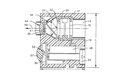
Referring to FIG.2 in conjunction with FIG. 1, it can be seen
that the threaded aperture 14 on the front surface 16 of the night vision
housing 12 defines an opening that termin~tes at the photocathode 28 of
an image intensifier tube 30. In the preferred embodiment, the image
intensifier tube 30 is a Generation II tube that creates an inverted image
at its output surface 32. A Generation III tube can be used in place of the
Generation II tube. However, the inverting fiber optic bundle normally
associated with a Generation III tube and sometimes the Generation II
tube need not be used. This provides a significant cost savings to the
m~nllf~ctllre of the night vision device 10, since the inverting fiber optic
bundle of a Generation II and Generation III tube are expensive optical
components. As low intensity light impinges upon the photocathode 28 of
the image intensifier tube 30, the low intensity light is amplified and
converted into an easily viewed image at the output surface 32 of the tube.
An inversion prism assembly 34 is disposed proxim~te the
output surface 32 of the image intensifier tube 30. The purpose of the
inversion prism assembly 34 is to invert the output image of the image
intensifier tube 30 in a confined area. The inversion prism assembly 34 is
used instead of a folded optic lens-based assembly to reduce the overall
size of the night vision device 10. In the shown embodiment, a Pechan
prism configuration is presented having a Schmidt prism 36 and a roof
prism 37. However, many other inversion prism assemblies can be used.
In the shown embodiment, the Schmidt prism 36 and the roof prism 37
combine to provide top/bottom and left/right inversion, thereby fully
erecting the output image of the image intensifier tube 30.
CA 0221~241 1997-09-11
WO 96/28753 PCT/US96/02772
In the shown embodiment, the image generated by the image
intensifier tube 30 follows the indicated optical path 40 through the
inversion prism assembly 34. The output surface 41 of the inversion prism
assembly 34 lays in the same line as does the optical axis of the image
intensifier tube 30. A doublet lens arrangement 44 is disposed prn~rim~te
the output surface 41 of the inversion prism assembly 34. The doublet lens
arrangement 44 receives the image from the output surface 41 of the
inversion prism assembly 34 and provides some collimation to the image.
As a result, an.y optical device coupled to the threaded ocular extension 18,
would receive a generally collimated image.
The various electrical potentials needed to operate the image
intensifier tube 30 are supplied by a power supply module 48. The power
supply module 48 preferably is a self-contained potted element and is held
in place by the space limitations of the housing 12. Electricity is provided
to the power supply module 48 from batteries in the battery port 24, via
a printed circuit board 50. An on/off switch 52 is disposed on the circuit
board 50 facing the ocular end of the night vision device 10. An
elastomeric button 57 extends through an aperture 55 in the housing and
engages the on/off switch 57. The elastomeric button 57 enables a person
to engage the on/off switch 52 and either enable or disable the night vision
10 device as desired, by disrupting the flow of electricity from the batteries
to the power supply module 48.
As can be seen from Fig. 1 and Fig. 2, the present invention
night vision device 10 contains a limited number of parts and has a very
compact size. The optical components, power supply module 48 and
battery port 24 are stacked in a vertical arrangement. To ",i"i",i,e size,
the height H of the housing 12 is just larger than the combined heights of
~ the optical components, power supply module 48 and battery port 24. The
CA 0221~241 1997-09-11
WO 96/28753 PCT/US96/02772
length L and the width W of the housing 12 are also selected to be just
large enough to cover the night vision components in their stacked
configuration.
Referring to Fig. 3, the present invention night vision device
10 is shown as part of a modular system having multiple optional objective
lens attachments and ocular lens att~chments. As can be seen, the present
invention night vision device 10 can be used as a self-contained viewing
device or as either an ocular lens or objective lens attachment for an
existing optical device.
When attaching a secondary lens system to the objective of
the night vision device 10 a connector may be required, if the thread size
of the threaded aperture 14 is not compatible with secondary lens system.
Three options that are available in connectors include the use of a
focusable connector 60, a static connector 62 or no connector at all. When
no connector is used, the secondary lens system would directly engage the
threaded aperture 14 on the first surface 16 of the night vision housing 12.
If a focusable connector 60 or static connector 62 are used, these
connectors would threadably engage the night vision housing 12 and would
provide a connector surface adapted to receive a specific type of secondary
lens system. The focusable connector 60 is a connector that can be varied
in its length L2 by rotation of a focus wheel 63 on its exterior surface.
Such devices are common place in focusable optical systems. As such, the
focusable connector can be used to vary the distance between a secondary
lens system attached to the focusable connector 60 and the input surface
of the image intensifier tube within the night vision device. This ability to
adjust the distance, enables the two devices to be focused in a manner that
would produce a clear image.
CA 0221~241 1997-09-11
W 096t28753 PCT~US96/02772
There are many different secondary lens systems that can be
attached to the objective of the night vision device 10. Those secondary
,. lens systems include a standard zero power objective lens assembly 65 that
is custom made for the night vision device 10 and may be sold with the
J 5 night vision device 10. The zero power objective lens assembly 65 enables
the night vision device 10 to be used as a simple night vision spotting
scope. Other secondary lens systems that can be used include, but are not
limited to, galilean telescopic lenses 66, camera lens 68, guns scopes 70, or
other miscellaneous optical devices 72 such as periscopes, telescopes and
the like.
A large variety of ocular lens assemblies are also available
for the present invention night vision device 10. These ocular lens
assemblies would engage the threaded ocular extension 18 extending from
the night vision housing 12. Those ocular lens assemblies include a simple
zero power eyepiece assembly 74 that is custom made for the night vision
device 10 and is preferably sold as part of the night vision device 10. In an
alternate embodiment a telescopic eyepiece 76 can be provided that would
magnify the output image created by the image intensifier within the night
vision device 10. The zero power eyepiece assembly 74 or telescopic
eyepiece 76 threadably engage the threaded ocular extension 18 in a
manner that optically aligns the eyepiece with the image created by the
night vision device 10.
An adaptor 80 may also be joined to the threaded ocular
extension 18, if the thread size of the ocular extension is not compatible
2~ with the secondary optical device. Similarly, the adaptor may be joined toeither the zero power eyepiece assembly 74 of the telescope eyepiece 76.
The adaptor 80 can be a 35mm "T" adaptor that enables the night vision
~ device to be coupled to a 35mm camera 81. The adaptor 80 could also
CA 0221~241 1997-09-11
WO 96/28753 PCT/US96/02772
join the night vision device to the objective lens of a video recorder 82, gun
scope 83, or television camera 84.
From the above description, it should be understood that the
present invention night vision device is a modular component that can be
coupled to either the objective lens assembly or the ocular lens assembly
of most any existing optical device, thereby providing that ocular device
with night vision capabilities. The night vision device contains little more
than an image intensifier tube and a prism system used to invert the image
produced by the image intensifier tube. The housing that contains the
night vision device is sized and shaped to be as small as is necessary to
envelop the various components of the night vision device, thereby
minimi7ing the size of the present invention.
The present invention night vision device shown in the figures
is merely exemplary. Numerous modifications in components, optical
orientations and materials could be made by a person skilled in the art.
For example, in the illustrated embodiment, the ocular output of the night
vision device is linearly aligned with the image input of the image
intensifier tube. It will be understood that by alternating the prism
assembly used to invert the image, a device with an off-set ocular output
can be obtained. All such variations and modifications are intended to be
included in the scope of this invention, as defined by the following claims.