Note: Descriptions are shown in the official language in which they were submitted.
CA 0221~4~4 1997-09-1~
VIBRATION DAMPING SHAFT LINER
This invention relates to a liner
especially adapted for use in an automotive drive
shaft for damping vibrations and attenuating noise.
It has been the practice for many years to
insert a cylindrical liner into a cylindrical
automotive drive shaft for the purpose of damping
vibrations and attenuating, at least to some extent,
noise transmitted along the shaft. Examples of such
liners are disclosed in U.S. patents Nos. 2,751,765;
4,014,184; 4,124,928; and 4,909,361.
Although the known liners have the
capability of functioning satisfactorily, several
factors may have an adverse effect on their
efficiency. For example, the liners obviously must
be manufactured prior to assembly with the drive
shafts and often must be shipped from the point of
manufacture to the point of assembly with the drive
shafts. During the time between manufacture and
assembly, the liners may be exposed to wide
variations in humidity. If the liners are formed of
paper, as is customary, and if the paper from which
the liners are formed is hygroscopic, as
conventionally is the case, humidity changes can and
CA 0221~4~4 1997-09-1~
do affect some of the properties of the liners.
If a liner is formed of a cylindrical
paper core having an exterior layer of corrugated
material, such corrugated layer having alternating
grooves and upstanding flutes, changes in humidity
may cause considerable variations in the resistance
to deformation of the flutes, as well as the spring
rate or recovery characteristic of the flutes from
such deformation. As a consequence, the force
required to insert a liner into a drive shaft may
vary considerably due to changes in humidity.
It is conventional to close the ends of a
drive shaft following insertion of a liner into the
shaft, thereby m;nimizing the effect of subsequent
changes in humidity. Following insertion of the
liner and closing the ends of the shaft, the shaft
containing the liner is balanced. However, if the
liner has shrunk radially due to a relatively low
humidity at the time of insertion of the liner in
its shaft, the position of the liner in the shaft
may change in response to torsional forces to which
the shaft is subjected following its inclusion in a
vehicle. Relative movement between the liner and
the shaft is objectionable because the shaft then
may become unbalanced, thereby defeating the
purposes for which the liner is incorporated in the
CA 0221~4~4 1997-09-1
shaft.
A liner constructed ln accordance with the
invention overcomes the disadvantages referred to
above.
A vibration damping liner for a
cylindrical drive shaft or other member comprises a
cylindrical core on the exterior of which is wound a
corrugated layer having alternating helical grooves
and flutes. The diameter of the liner at the flutes
is greater than the inside diameter of the shaft,
thereby necessitating deformation of the flutes to
insert the liner in the shaft. The flutes are '
subjected to a deforming treatment prior to the
application of the corrugated layer to the core
which deforms each flute in a direction transversely
of its length. The deforming treatment reduces the
flute diameter of the liner to one that is less than
the undeformed flute diameter of the liner, but
still is greater than the diameter of the bore. The
material from which the flutes are formed is
resilient so that each flute is flexible and bears
yieldably against the surface of the bore.
Preferably, the opposite ends of each flute are
collapsed to a height less than that of the
remainder of such flute.
-- 3
CA 0221~4~4 1997-09-1~
Some or all of the flutes may be coated
with frictional material which has a coefficient of
friction considerably greater than that of the
material from which the flutes are formed, but such
frictional material does not prevent radial flexing
of the flutes.
Following lateral deformation of the
flutes and collapsing of their ends, the corrugated
material is wound on and secured to the core. The
coating of frictional material may be applied to the
corrugated material either before, during, or
following winding of the corrugated material on the
core.
The flutes are deformed in one direction
only, thereby facilitating temporary radial
contraction of the liner by a sizing ring as the
liner is inserted in a shaft. As the liner passes
through the sizing ring into the shaft the flutes
expand radially into engagement with the surface of
the bore. The resilience of the material from which
the flutes are formed causes them to expand radially
even more, thereby causing the flutes to bear
forcibly on the surface of the bore. The tendency
of the flutes to expand radially causes the
frictional coating also to bear on the surface of
the bore, thereby providing considerable resistance
CA 0221~4~4 1997-09-1~
to relative movement of the liner and shaft
following insertion of the liner into the shaft.
A vibration damping liner constructed in
accordance with preferred embodiments of the
invention are disclosed in the accompanying
drawings, wherein:
Figure 1 is an elevational view, with
parts broken away, of one embodiment of the
invention;
Figure 2 is a transverse sectional view of
the damping liner within a cylindrical shaft;
Figure 3 is a sectional view through a
conventional single faced layer of corrugated paper;
Figure 4 is a view similar to Figure 3
illustrating the flutes of the corrugations
collapsed in the conventional manner;
Figure 5 is a sectional view showing
deformation of the corrugated flutes according to
the invention;
Figure 6 is a fragmentary sectional view
illustrating the apparatus shown in Figure 5;
Figure 7 is a view similar to Figure 1,
but illustrating a further embodiment; and
Figure 8 is a flow diagram illustrating
the procedural steps of forming the liners of
CA 0221~4~4 1997-09-1
Figures 1 and 7.
A vibration damping liner constructed in
accordance with one embodiment of the invention is
designated generally by the reference character 1 in
Figure 1 and comprises a cylindrical core 2 formed
of kraft or other suitable paperboard as is
conventional. On the outer surface of the core is
wound and secured a continuous strip 3 of single
faced, corrugated paper formed in the conventional
manner from kraft or other suitable paperboard which
has some resilience. As shown in Figure 3, the
corrugated strip 3 has a base 4 to which is secured
an overlying strip S of paper having alternating
grooves 6 secured to the base and upstanding,
curvilinear flutes 7.
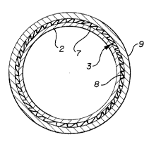
The liner is adapted to be inserted into
the bore 8 of a cylindrical drive shaft or other
hollow member 9 having a smooth surface. The
diameter of the core 2 is less than that of the bore
8, but the maximum diameter of the liner 1 through
the upstanding, undeformed flutes 7 (hereinafter
referred to as the undeformed flute diameter) is
greater than that of the bore 8.
Insertion of the liner 1 into the shaft 9
may be effected by apparatus such as that disclosed
CA 0221~4~4 1997-09-1~
in U.S. patent No. 4,124,928 which includes a sizing
ring that deforms the flutes of the corrugated strip
3. Deformation of the flutes 7 according to the
prior art produces radially outward concave surfaces
10 terminating at their opposite ends in convex ribs
11 and 12, as shown in Figure 4. As a consequence,
when a liner having flutes deformed as is shown in
Figure 4 is inserted in the bore of a shaft, only
the ribs 11 and 12 will engage the inner surface of
the bore; and such ribs have little, if any,
springiness.
A liner 1 formed in accordance with the
invention commences with the formation of the core 2
on which subsequently is wound a corrugated layer 13
composed of the corrugated strip 3 modified as
described below. The core is conventional and
comprises a plurality of plies of paperboard or
other suitable material. However, prior to winding
the corrugated strip 3 on the core 2, the strip 3 is
placed on a support 14 and passed beneath a rotary
deforming roller 15 in the direction of the arrow A
in Figure 5. The roller 15 rotates in the direction
of the arrow B and comprises a spindle 16 and a
cylindrical section 17 terminating at each end in an
enlarged cylindrical rim 18.
As is best shown in Figure 5, the height
CA 0221~4~4 1997-09-1~
of the periphery of the cylindrical section 17 from
the upper surface of the support 14 is less than the
height of the undeformed flutes 7 so that movement
of the corrugated strip 3 beneath the roller 15
causes the flutes 7 to be deformed longitudinally of
each flute, as is shown in Figure 5. As each flute
passes beneath the roller 15, the central section 17
thereof causes such flute to be deformed to a height
above the support 14 that is substantially lower
than that of the height of the undeformed flute.
For example, if the height of the undeformed flute
is .180 inch, each flute passing beneath the central
section 17 of the roller 15 temporarily may be
deformed to a height of .100 inch. This deformation
is indicated at 7a in Figure 5.
Since the material from which the flutes
are formed is resilient, disengagement of each flute
from the central section of the roller enables the
deformed flute to spring back to a height that is
between its maximum deformation and its original
undeformed height. This characteristic is shown by
the flute 7b in Figure 5. The spring back or
permanent deformation height of the deformed flute
7b may be .150 inch.
If a corrugated strip such as the strip 3
is spirally wound on the core 2, as is shown in
-- 8 --
CA 0221~4~4 1997-09-1~
Figure 1, that portion of the corrugated layer at
each end of the liner forms what is known as a tail.
Such a tail is indicated at 19 in Figure 1. Tails
have a tendency to separate from the core because of
the small area of the tail and the consequently
small adhesive bond available. Separation of the
tails may be overcome or greatly m;~;m; zed by
collapsing the opposite ends of each of the flutes 7
as shown at 7c in Figure 6. The collapsing of the
flutes results in a liner diameter that is minimum
at the ends of the flutes and the collapsing is
achieved by the rims 18 of the roller 15 at the same
time that the other parts of the flutes are
deformed. The collapsing or flattening of the ends
7c of the flutes virtually destroys all of the
resiliency of the material from which the flutes are
formed, thereby preventing the spring-back
tendencies of an unflattened or partially flattened
flute to cause the tail 19 to separate from the
core.
The corrugated layer 13 comprises the
strip 3 having the deformed flutes 7b and the
collapsed flute ends 7c.
As has been indicated above, the process
of constructing the liner comprises forming the core
2, deforming all of the flutes 7 laterally of their
g _
CA 0221~4~4 1997-09-1~
length and in the same direction and, at the same
time, flattening the ends 7c of the flutes,
following which the corrugated layer 13 is wound on
and secured to the outer surface of the core 2.
In the condition of the liner 1 prior to
its assembly with the shaft 9, the diameter of the
liner through diametrally opposite deformed flutes
7b (hereinafter the deformed flute diameter) is
greater than the diameter of the bore 8 of the shaft
9. Accordingly, the liner should be introduced to
the bore via a sizing ring which will compress the
flutes 7b radially inwardly so as temporarily to
reduce the deformed flute diameter of the liner to
one that is less than or corresponds substantially
to the diameter of the bore 8. As the liner passes
into the bore of the shaft, the resilience of the
material from which the flutes are formed enables
the flutes compressed by the sizing ring to spring
back or expand radially outwardly and bear forcibly
against the inner surface of the bore.
From a comparison of the flutes 7b shown
in Figure 5 with the flutes shown in Figure 4, it is
clear that each flute 7b has a much greater surface
area available for engagement with the inner surface
of the bore of the shaft 9. Consequently, the
greater surface contact, coupled with the constant
-- 10 --
CA 0221~4~4 1997-09-1~
biasing of the flutes 7b toward the inner surface of
the bore, enables the liner 1 to resist
significantly any movement relative to the shaft 9.
However, because of the substantially uniform
deformation of all flutes in the same direction, the
insertion of the liner in the shaft 9 requires
considerably less force than is required to insert a
conventional liner in a corresponding shaft.
In the embodiment shown in Figure 7, the
liner 20 corresponds to and is formed in the same
way as that described earlier, but differs from the
latter by the inclusion of a coating 21 of
frictional material on some or all of the
convolutions of the corrugated layer 13. The
coating should be applied at least to the central
part of the liner, i.e., axially inward of its ends,
but such coating may be applied to the entire length
of the liner.
The frictional material should be one that
has a considerably higher coefficient of friction
than the material from which the corrugated layer 3
is formed and, of course, higher than that of the
inner surface of the bore 8. The frictional
material also should be one which does not inhibit
radial flexure or deformation of the flutes 7. One
suitable frictional material is commercially
CA 0221~4~4 1997-09-1~
available, high friction polyurethane. Another is
formulated rubber latex such as that manufactured by
National Starch and Chemical Company, Bridgewater,
N.J., and described in its Specification 35-6198
relating to Resyn Self Seal. The coating of the
flutes with the frictional material enhances the
resistance to relative movement between the liner 1
and the shaft 9.
Although liners constructed in accordance
with the invention may suffer the same exposure to
varying humidity conditions as liners produced
heretofore, the springiness of the deformed flutes
and the relatively large surface area thereof that
is engageable with the inner surface of the bore 8
enables liners constructed in accordance with the
invention to exhibit satisfactory resistance to
movement relative to the shaft.
Figure 8 illustrates the operative steps
of forming the liner which comprise forming the
core, deforming the corrugation flutes, applying the
corrugated layer to the core and, when desired,
applying the frictional coating to some or all of
the flutes. It is possible to vary the order of the
manipulative steps. For example, the frictional
coating could be applied prior to deformation of the
flutes or it could be applied prior to the
CA 0221~4~4 1997-09-1~
application of the corrugated layer to the core.
The disclosed embodiments are
representative of presently preferred forms of the
invention, but are intended to be illustrative
rather than definitive thereof. The invention is
defined in the claims.