Note: Descriptions are shown in the official language in which they were submitted.
-
CA 0221~01 1997-09-16
PCT/~ 5GJW~07
W096/29553
COOLING SYSTEM FOR ELECTRONICS
TECHNICAL FIELD
The present invention relates to a cooling system, and then
more particularly to a system for cooling electronic compo-
nents which utilizes a thermosiphon effect to circulate the
refrigerant used in the system. The system comprises an
hermetically closed pipe circuit which includes an evaporator
and a condenser, wherein the evaporator is in heat-conducting
contact with a heat-emitting component to be cooled and
absorbs heat therefrom, this heat being transported by the
refrigerant through the pipe circuit and to the condenser and
dissipated therein.
DESCRIPTION OF THE PRIOR ART
In principle a thermosiphon circuit is comprised of an
evaporator and a condenser which are incorporated in a pipe
circuit. The circuit is hermetical and is filled with a
coolant or refrigerant suitable for the purpose intended. In
order for the circuit to function, it is necessary for the
condenser to be located somewhat above the evaporator. When
heat is delivered to the evaporator, part of the coolant will
boil off and a mixture of liquid and gas rises up to the
condenser. The coolant condenses in the condenser and heat
is released. The liquid thus formed then runs bac~ to the
evaporator under its own weight.
Thermosiphon circuits are normally very efficient heat
transporters, insomuch as heat can be transported through
long distances at low temperature losses. They can therefore
be used advantageously for different cooling purposes.
Furthermore, there is generally a great deal of freedom in
the design of the evaporator and condenser. In the context
of electronic component cooling, however, the components to
be cooled are normally very small, which means that the
CA 0221~01 1997-09-16
PCT/SE96/00307
W096l29553
evaporator must also be small. The external cooling medium
used is normally air, which in turn means that the condenser
must have a large external surface area. In these contexts,
it can therefore be said that a thermosiphon circuit is an
apparatus with whose aid very large surface enlargements can
be obtained and that these surface enlargements can further-
more be placed at a long distance from the heat source.
One of the drawbacks with thermosiphon circuits is that the
condenser must always be placed higher than the evaporator.
In present-day electronic systems comprising a large number
of densely packed components of which several need to be
cooled, cooling is difficult to achieve because each of these
heat-emitting components requires its own evaporator with
associated condenser. Difficulties are encountered in laying
out the pipes that form the pipe circuits and also in
suitable positioning of the condensers.
SUMMARY OF THE l~v~NlION
The object of the present invention is to avoid the drawbacks
of existing thermosiphon circuits, by providing a cooling
system which does not require complicated pipe lay-outs, and
with which positioning of the condenser is not restricted to
Z5 the same extent as in earlier known systems of this kind.
This object is achieved with a cooling system having the
characteristic features set forth in the following Claims.
The invention is based on the concept that when more than one
evaporator is used, the evaporators can be connected in
series to provide a pumping action which will enable one or
more evaporators to be situated above the condenser liquid
level. This greatly increases the degree of freedom in
condenser placement. In an electronic component cooling
context, it may also be assumed that a number of components
located at mutually different heights will normally require
some form of additional cooling. In some cases, the liquid
CA 0221~01 1997-09-16
W096/29553 PCT/SE96/00307
that is entrained with the gas that boils-off in the evapora-
tors is able to improve the function, whereas in other cases
the liquid can present a problem. However, the liquid content
of this two-phase mixture can be regulated to a great extent
with an evaporator construction of suitable design.
The invention will now be described in more detail with
reference to a preferred embodiment thereof and also with
reference to the accompanying drawings.
BRIEF DESCRIPTION OF THE DRAWINGS
Figure 1 is a diagrammatic illustration of the principles of
a known thermosiphon circuit.
Figure 2 is a diagrammatic illustration of the principles of
an inventive thermosiphon circuit.
Figure 3 is a side view of an evaporator used in an inventive
thermosiphon circuit and also presents two different section-
al views of the evaporator.
Figure 4 illustrates an embodiment of the use of an inventive
thermosiphon circuit in a so-called multichip module.
DETAILED DESCRIPTION OF A ~:~ ~ ~ EMBODIMENT
Figure 1 illustrates schematically the principles of a known
thermosiphon circuit comprising an evaporator 1 and a
condenser 2 which are connected in a pipe circuit 3. The
circuit is hermetical and is filled with a cooling medium
suitable for the purpose intended. When heat is delivered to
the evaporator 1, part of the medium will boil off and a
mixture of liquid and gas rises up in the pipe circuit 3,
towards the condenser 2. The medium is condensed in the
condenser 2 and heat is released. The liquid thus formed then
runs back to the evaporator, under its own weight. The
_
CA 0221~01 1997-09-16
PCT/~ G~'~~307
WO 96t29553
transfer of heat is shown schematically by the heavy arrows
in Figure 1, while refrigerant circulation is shown by the
smaller arrows. In order for the circuit to function, it is
necessary for the condenser liquid level to be slightly
higher than the evaporator.
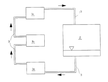
Figure 2 illustrates diagrammatically the principles of an
inventive thermosiphon system. By connecti~g a plurality of
evaporators la, lb and so on in series in the pipe circuit
3, pumping of the refrigerant used in the pipe circuit can
be elevated, while the condenser 2 can be positioned so that
the level of the condensed liquid refrigerant therein lies
beneath the highest evaporator lc in the pipe circuit, as
evident from the Figure. The reason for this is because the
intrinsic weight, or dead weight, of the liquid leaving the
condenser 2 is much greater than the intrinsic weight, or
dead weight, of the two-phase mixture leaving the bottom
evaporator la. The two-phase mixture is therewith driven
upwards and the liquid entrained therewith can be used to
ZO evaporate the liquid in the upper evaporators lb, and so on.
This pump principle is known in the literature under the
designation airlift pump.
In this context, the function is improved by the liquid that
is entrained with the gas that boil off in the evaporators.
The liquid content of the two-phase mixture can be regulated
to a great extent by suitable choice of drive height, pipe
diameters and evaporator design. Practical tests have shown
that one heat transfer improvement factor is a combination
of high pressure and narrow passageways. Heat transfer
numbers have been measured which have a factor 5-10 times
higher than what is normal in other contexts in which boiling
media are used .
Figure 3 illustrates the construction of an evaporator 1. A
metal body 4 includes an inlet chamber 5 and an outlet
chamber 6 which are mutually connected by a large number of
CA 0221~01 1997-09-16
PCr/~h9G,1~0307
Wo96/29553
narrow passageways 7 having a diameter of millimeter size.
The construction can be made so that the total mantle surface
of these passageways is much greater than the front surface
of the metal body. Heat transfer can be greatly improved in
this way, in certain cases.
An inventive cooling system finds particular use in connec-
tion with so-called multichip modules. A multichip module can
be said generally to comprise a capsule which contains more
than one microcircuit. In modern electronics, these modules
often have the form of a small circuit board with dimensions
that can vary from the size of a postage stamp to the size
of the palm of a hand. One of the advantages afforded by
multichip modules is that the microcircuits can be placed
close together and therewith enable high signal speeds to be
used. One of the drawbacks with multichip modules is that the
cooling problem is difficult to overcome.
A multichip module will often have a very large number of
electrical connections and must therefore be attached
parallel with the circuit board on which the module is used.
As a result, only one side of the multichip module can be
used for cooling with air, which presents a serious problem.
When cooling is effected from the carrier side, this side
must be a good conductor of heat and the microcircuits must
also be effectively coupled thermally to the carrier. When
cooling is effected from the microcircuit side, their compo-
nent carrying surfaces must face downwards and the cooling
body must also be adapted for connection to circuits at
different heights , at least in the majority of cases in
practice,. Problems which greatly restrict freedom of
construction thus occur in both cases.
It is therefore obvious that two-sided cooling, which can be
achieved with an inventive thermosiphon circuit, would
provide significant advantages. The principle is illustrated
in Figure 4. A multichip module 8 is affixed parallel with
CA 0221~01 1997-09-16
PCT/SI~9 ~,/00~07
WO 96/29553
a circuit board 9. Located on the carrier side of the
multichip module 8 is a fin cooler 10 with a condenser 2
integrated in the bottom plate 11. The condenser is suitably
comprised of a plurality of vertical passageways or channels
having a cross-sectional area optimal for the purpose
concerned. The evaporators la and lb of the thermosiphon
circuit are situated on the microcircuit side of the module
8 and mounted on those microcircuits that have the highest
power losses. The cooling system operates in the same manner
as that described above with reference to Figure 2.
It is fully possible to drive the circulation in a thermosi-
phon circuit with solely some centimeters difference in
height between the level of liquid in the condenser and the
lowermost evaporator. Liquid can be delivered to the remain-
ing evaporators through the pumping action achieved with the
series connection described above. The level of liquid in the
condenser can therefore be kept low, which results in
effective use of the condenser surfaces.
It will be understood that the invention is not restricted
to the aforedescribed and illustrated embodiment thereof, and
that modifications can be made within the scope of the
following Claims.