Note: Descriptions are shown in the official language in which they were submitted.
CA 02215599 1997-09-16
DEVICE FOR OPERATING A DISCHARGE LAMP
Background of the Invention
Field of the invention
The invention relates to a device for operating a fluores-
cent discharge lamp of the outer electrode type which is
used for document scanning illumination of an information
processing device, such as a fax machine, a copier, an ima-
ge reader and the like, and for a back light device of a
liquid crystal display and for similar purposes.
Description of Related Art
A fluorescent dischargA lamp of the outer electrode type 3s
known as a fluorescent lamp which is used for document
scanning illumination of an office automation device and
for back light of a liquid crystal display of an office au-
tomation device and the like.
In the above described fluorescent discharge lamp of the
outer electrode type, on the outside of a glass tube there
is a pair of line-like or strip-like outer elQCtrodes to
which as uninterrupted high frequency voltage or a pulse-
like high frequency voltage is applied to operate the lamp.
Figure 12 is a schematic of an arrangement of the above
described fluorescent discharge lamp of the outer electrode
__. type. Figure 12 (a) shows a cross section of the fluores-
CA 02215599 1997-09-16
-
cent discharge lamp of the outer electrode type which cor-
responds to the direction perpendicular to the direot3on of
the tube axis. Figure 12 (b) is a side view hereof.
As becomes apparent from Figure 12, fluorescent discharge
lamp of the outer electrode type 1 consists of discharge
vessel 3 which consists of a dielectric such as glass or
the like, a pair of strip-like or line-like electrodes 2,
2', and layers of fluorescent material 4 which are formed
on the inside of discharge vessel 3. Electrodes 2, 2' are
locatQd on the side of discharge vessel 3 in the direction
of the tube axis roughly over the entire length and consist
of aluminum of the like.
Conventionally, above described fluorescent discharge lamp
of the outer electrode type 1 has been operated by applying
a high frequency voltage to the outer electrodes as in a
cold cathode fluorescent discharge lamp of the inner elec-
trode type. That is, high frequency main circuit 5 as shown
in Figure 13 is connected to the pair of electrodes 2, 2'
of fluorescent discharge lamp of the outer electrode type
1. For example, a waveform high frequency AC voltage accor-
ding to Figure 14 is applied to electrodes 2, 2'. In this
way a high frequency voltage is applied in the discharge
space within discharge vessel 3 which is present between
outer electrodes 2, 2' via the side discharge vessel 3,
forming a discharge.
This approach is disclosed in the patent disclosure docu-
ment of Japanese patent application HEI 3-225745 (US Patent
5, m~, ma ~ .
~n the above described conventional operation method there
is a process with which the illuminance of the fluorescent
CA 02215599 1997-09-16
- 3 -
discharge lamp of the outer electrode type is increased
even more. In this process the gas pressure of the rare gas
which is filled within discharge vessel 3 is increased.
In the above described case of increasing the filling pres-
sure howEVer the current required for discharge is riot suf-
ficient if the voltage applied to the fluorescent discharge
lamp of the outer electrode type is not increased. In this
case a stable dischargE cannot be obtained.
In the following the shape of the discharge within dischar-
ge vessel 3 is detailed in the case of increasing the fil-
ling pressure:
In this discharge, over the entire region of the lamp a
plurality of locations at which emission is concentrated is
formed. This plurality o~ local sites at which the emission
is concentrated furthermore changes their positions over
time. The emission state in discharge vessel 3 is observed
in the form of a strip. Figure 15 schematically shows this
strip-like discharge phenomenon.
Fluorescent discharge lamp of the outer electrode type 1
shown in Figure 12 can be called s capacitor which consists
of outer electrodes 2, 2' and discharge vessel 3 as the
dielectric. The lamp current which is supplied to this
fluorescent discharge lamp of the outer electrode type 1 is
determined by the magnitude of electrostatic capacity which
is formed between outer electrodes ~, 2' and discharge ves-
sel 3 which consists of the dielectric. Current must be
supplied to increase the illuminance of fluorescent disch-
arge lamp of the outer electrode type 1 even more. This
means that the voltage applied to outer electrodes 2, 2'
and the high frequency of the voltage must be increased.
CA 02215599 1997-09-16
_ ,g -
When the applied voltage was increased however the disad-
vantages of the danger of formation of creeping discharge
on the surface of the dielectric between outer electrodes
2, 2' and the danger of formation of an insulation break-
down in the circuit arose.
Sumootiary of the znventxon
The invention is devised to eliminate the above described
disadvantage. Therefore the object of the invention is to
devise a device for operating a fluorescent discharge lamp
of the outer eleotz~ode type in which even when the pressure
of the filled gas is increased in the discharge vessel a
stable discharge can be maintained and in which at the same
time higher illuminance can be obtained.
In the conventional operation method in which a sine curve
is applied the phenomenon shown above in Figure 15 occurs
when the pressure of the xare gas filled within discharge
vessel 3 and the voltage applied to discharge lamp 1 are
increased, as was described above. Therefore a stable
discharge cannot be maintained.
As the result of various experiments and tests it has been
shown that by operating discharge lamp 1 by applying a pe-
riodic voltage waveform with a steep start-up and maximum
peak waveform in wh~.ch the width with respect to repetition
period t is less than or equal to a stipulated value, a
stable discharge can be maintained even when the prESSUre
of the filled gas increases.
This means that it was found that by applying a periodic
voltage waveform to discharge lamp 1 in full width at half
maximum lies within a stipulated value, even when the pres-
CA 02215599 2001-07-30
- 5 -
sure of the filled gas increases, a stable discharge can be
maintained and the illuminance intensity can be increased,
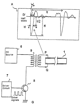
when for a voltage waveform measured at the two ends of the
lamp (voltage between P and Q in Figure 1) the width between
two points a and b is defined as full width at half maximum.
The voltage at two points a and b has a value (H/2 in the
Figure) which, proceeding from the position in which a
waveform with a maximum peak value of the voltage within the
above described one period intersects voltage OV has half the
maximum peak value (H in the figure) as is illustrated in
Figure lA.
Accordingly, one aspect of the present invention provides a
device for operating a fluorescent discharge lamp of the outer
electrode type in which at least one of the rare gases He, Ne,
Ar, Kr and Xe is hermetically sealed within a glass tube and
in which a fluorescent material is applied to an inner side of
the glass tube, and in which at least two strip-shaped
electrodes extend along an outer side of the entire length of
the glass tube in an axial direction thereof, comprising:
circuit means for applying a lamp voltage to the electrodes
which has a periodic voltage waveform with a single maximum
peak value within a repetition period t that is greater than
twice the width of the waveform at a voltage of O V (2Wo), the
circuit means comprising a flyback type circuit, wherein
within the repetition period t the waveform is set to a
predetermined value in the range of 10NS<=t<=30 NS , and
wherein there are no inner electrodes on the inner side of the
glass tube.
Another aspect of the present invention provides a fluorescent
discharge lamp of the outer electrode type in which at least
one of the rare gases He, Ne, Ar, Kr and Xe is hermetically
sealed within a glass tube having no inner electrodes and in
which a fluorescent material is applied to an inner side of
the glass tube, and in which at least two strip-shaped
electrodes extend along an outer side of the entire length of
the glass tube in an axial direction thereof, and having
CA 02215599 2001-07-30
- 5A -
circuit means for applying a lamp voltage to the electrodes
which has a periodic voltage waveform with a single maximum
peak value within a repetition period that is greater than
twice the width of the waveform at a voltage of O V, the
circuit means comprising a flyback type circuit, wherein
within the repetition period t the waveform is set to a
predetermined value in the range of 10 NS<=t<=30 NS.
A further aspect of the present invention provides a method of
operating a fluorescent discharge lamp of the outer electrode
type in which at least one of the rare gases He, Ne, Ar, Kr
and Xe is hermetically sealed in within a glass tube having no
inner electrodes, and in which a fluorescent material is
applied to an inner side of the glass tube, and in which at
least two strip-shaped e:Lectrodes extend along an outer side
of the entire length of the glass tube in an axial direction
thereof, comprising the step of applying a lamp voltage to the
electrodes which has a periodic voltage waveform with a single
maximum peak value within a repetition period t that is
greater than twice the width of the waveform at a voltage of O
V, and whereby the step of applying the lamp voltage comprises
using a flyback type circuit, wherein within the period t, the
waveform is set to a predetermined value in the range of
Thus, the invention is achieved as follows, based on the above
described principle:
In a device for operating a fluorescent discharge lamp of
the outer electrode type, in which within a glass tube at
least one of rare gases He, Ne, Ar, Kr or Xe is/are
hermetically sealed in a stipulated amount, in which
fluorescent material is applied to the inside of the
above described glass tube, and in which in the axial
direction of the outside of the above described glass
tube there are at least two strip-shaped electrodes,
operation of the above described discharge lamp is
CA 02215599 2001-07-30
- 5B -
effected by applying a voltage with a periodic wavef.orm,
in which with respect to repetition period t of the
voltage waveform 2 W~< T, if the width at a voltage of
the waveform of O V which has a single maximum peak value
within a period for a periodic waveform of the lamp
voltage is labelled W~.
This makes it possible to maintain a stable discharge even
when the pressure of the gas filled in the discharge lamp is
increased, and to increase the illuminance more than in
CA 02215599 2000-02-04
- 6 -
the conventional operation method in which the sine curve is applied
(2) In the above described device for operating a discharge
lamp, discharge lamp 1 is operated by applying a voltage
with a periodic waveform, in which full width at half
maximum of a waveform with a maximum peak value at the
operating lamp voltage satisfies condition W < Wx, if with
respect to the repetition period t of the voltage of the
waveform 2Wo < t, and if the width at a voltage of the
waveform of 0 V has a single maximum peak value within
one period at the periodic waveform of the lamp voltage
(Wok. Furthermore the maximum illuminance is labeled L,
which in the case of operation of the above described lamp
is obtained by a sine curve, if the same lamp wattage as in
this case is supplied under the aforementioned conditions,
and if the full width at half maximum of a waveform with a
maximum peak value at which the above described
illuminance L can be obtained is designated Wx.
(3) For (1) and (2) full width at half maximum of the waveform
with the maximum peak value is fixed in the range of W <_
2.5 ,u sec.
(4) For (1 ) and (2) period t of the periodic voltage waveform is
fixed in the range from 5 ,u sec to 70 ,u sec.
(5) For (1 ) and (2) a fluorescent discharge lamp of the
outer electrode type is operated in which within the
glass tube a gas with a partial pressure of the Xe gas
of greater than or equal to 80 torr and a total pres-
CA 02215599 2000-02-04
sure of the filled gas of less than or equal to 760 torr is filled.
(6) For (1) and (2) an oscillation wave which follows the
maximum peak voltage is supplied with an effective power
which contributes to emission.
(7) For (1) and (2) the periodic waveform of the lamp voltage is
produced by a circuit of the flyback type.
The device described above in (1 ) to (7) for operating a
discharge lamp makes it possible to maintain a stable
discharge even when the pressure of the gas filled in the
discharge lamp is increased, and to further increase the
illuminance more than in the conventional operation method
in which the sine curve is applied.
In the following the invention is described using several embodiments
shown in the drawings.
Fig. 1 shows a schematic of one arrangement of a basic circuit of
the flyback type of one embodiment of the device as
claimed in the invention for operating a discharge lamp;
Fig. 2 shows a schematic of an arrangement of a circuit of the
flyback type of another embodiment of the operation device
as claimed in the invention;
Fig. 3 shows a schematic of one arrangement of a MOSFET circuit
intrinsically including one diode;
CA 02215599 1997-09-16
Fig. 4 shows a schematic of one arrangement of an
experimental cirouit of the flyback type which
is used in the invention;
Fig. 5 shows a schematic of the relation between the
full width at half maximum and the illuminance
of the discharge lamp (with 8 mm diameter);
Fig. 6 shows a schematic of the relation between the
full width at half maximum and the illuminance
of the discharge lamp (with 6.5 mm diameter):
Fig. 7 (a) through Figure 7 (d) each show one schematic
of the lamp voltage waveform in operation of
the discharge lamp;
fig. 8 shows a schematic of the relation between the
lamp watt8.ga and the illuminance with different
waveforms;
Fig. 9 shows a schematic of the relation between the
operation period and the illuminance;
Fig. 10 shows a schematic of the relation between the
partial pressure of the Xe gas and the relative
luminance fluctuation;
Fig. I1 shows a schematic of the relative between the
mixing ratio of Ne and the illuminance;
Fig. 12 (a) shows a schematic cross section of one arrange-
ment of a fluorescent discharge lamp of the
outer electrode type; and
CA 02215599 1997-09-16
_ g _
Fig. 12 (b) shows a schematic side view of the arrangement
according to Figure 12 (a);
Fxg. 13 shows s schematic of a circuit of a conventio-
nal operation type using a sine curve high fre-
quency of a fluorescent discharge lamp of the
outer electrode type:
Fig. 14 shows a schematic of a voltage waveform for
operation of a conventional fluorescent dis-
charge lamp of the outer electrode type; and
Fig. 15 shows a schematic of a pnenomenon of unstable
discharge which occurs at a high pressure of
the filled gas.
Detai~.ed Descriptions of Preferred Embadimentr,
Figure 1 is a schematic of an arrangement of a basic cir-
cuit of one embodiment of the device as claimed in the in-
vention for operating fluorescent discharge lamp 1 of the
outer electrode type (hereinafter called a discharge lamp).
Furthermore, reference number fi labels a DC source, refe-
rence number 7 a driver circuit, reference number 8 a swit-
ching device, and reference number 9 a transformer. This
figure shows the arrangement of a basic circuit of the fly-
back type. Switching device 8 is turned on and off by drill
ver signals with a stipulated frequency which is delivered
by driver circuit 7. If switching device 8 is turned on by
the above described driver signaJ.s, current flows via a li-
ne from DC source 6 via the primary winding of transformer
9, switching device 8 to ground G, and energy is stored in
transformer 9.
CA 02215599 1997-09-16
- 10 -
When switching device $ is turned off, the Current flowing
through transformer 9 is turned off. The above described
energy stored in transformer 9 is therefore released. On
the primary side and secondary side of transformer 9 this
yields the voltage waveform shown at A in Figure 1 with a
steep rise. This voltage waveform is attenuated with an at-
tenuation constant which corresponds to the line constant.
If switching device 8 is turned on and then turned off suc~
cessively a voltage waveform with a steep rise is formed
again in the above described manner.
As Was described above, each time switching device 8 is
turned on/off with a stipulated frequency by the driver
signals output by driver circuit 7, the voltage waveform
with a steep rise is formed repeatedly on the secondary side
of transformer 9, as is illustrated at A in Figure 1. This
voltage waveform is applied to discharge lamp 1.
In the above described device for operating a discharge
lamp, as was described above, by fixing full width at half
maximum of the above described voltage waveform within a
stipulated value and by application thereof with the stipu-
lated repetition period t to discharge lamp l, a stable
discharge can be maintained, even if the pressure of the
gas filled in dischargE lamp 1 is increased.
One conceivable reason for this is the following: If a vol-
tage with a short starting time, i.e., a voltage which con-
tains a high percentage of high frequencies, is applied to
discharge lamp l, discharge vessel 3 consisting of glass or
the like does not in fact act as a dielectric, and thus an
approximation to a state is achieved in which a voltage is
applied directly to the gas filled inside.
CA 02215599 1997-09-16
- 11 -
That is, in the discharge lamp which is operated via the
glass, the latter is a dielectric. If a voltage is applied
to the lamp, this glass surface is therefore electrified
and discharge begins if a breakdown voltage is achieved.
This dischargE immediately neutralizes the glass surface
arid then stops because there is no longer 8ny potential
gradient. When the next discharge begins, the glass surface
is neutralized again and the discharge stopped 3n the same
way. This process ~.s repeated. This phenomenon arises de-
pending on the condition of the glass surface and the re-
spective electrification condition in each area of the
glass surface.
When the voltage applied to the lamp is a sine curve, the
voltage increases relatively gently, and a voltage waveform
of this type occurs continually and repeatedly. These phe-
nomena therefore always occur and it is conceivable that
apparently a strip-like discharge would occur, as was des-
cribed above.
In the case of a conventional luminous operation process in
which a sine curve is applied, therefore at a partial pres-
sure of the Xe gas of greater than or equal to 80 torr, the
above described phenomenon occurs and relative luminance
fluctuation is acutely increased if the pressure of the gas
encapsulated in the discharge lamp is increased to raise
the illumination intensity, as is described below.
If, on the other hand, a voltage waveform with s short ri-
sing time is applied to the lamp, a condition approximated
in which the voltage is applied directly to the gas itself
filled in discharge vessel 3, as was described above. The
above described phenomenon of neutralization of the surface
of the dielectric is therefore reduced. zt is conceivable
CA 02215599 1997-09-16
- 12 -
that a strip-like discharge would not occur and that a
stable emission would be produced.
Here the illumination intensity of the ultraviolet radia-
tion which are em~ttted from the Xe gas of discharge lamp 1
decreases both at an overly high repetition frequency of
the above described voltage applied to discharge lamp Z
(called the "operation frequency"), and also at an overly
low operation frequency. The possible reason for this fs as
follows:
(1) in the case of a reduction of the luminous frequency
If the operation frequency is reduced With a constant
input power, the energy per repetition of the lamp vol-
tage waveform increases according to the reduction of
the operation frequency. On the other hand, the radiant
efficiency of Xe decreases when the input energy is in-
creased. It is therefore conceivable that the lower the
~.uminous frequency is made, the more the radiant effi-
ciency and the illuminanoe decrease.
(2) in the case of an increase of the operation frequency
Based on the aforementioned explanation (1), the illu-
minance does increase up to a certain frequency when
the operation frequency is increased. But if the fre-
quency is increased even more, the next voltage wave-
form destroys the excitation species which produce the
ultraviolet radiation, thus causing the iliuminance to
decrease.
The conce~.vabie reason for this is that in conjunction
with the lifetime of the excitation species, still. re-
maining excitation species are destroyed by the energy
CA 02215599 1997-09-16
- 13 -
Obtained during the next period arid that emission with
good radiant efficiency is no longer obtained from the
excitation species if the next voltage waveform With an
earlier period than the lifetime o~ the excitation spe-
cies once produced is applied to the discharge lamp.
As was described above, by fixing full width at half maxi-
mum of the voltage applied to discharge lamp 1 within a
stipulated value and furthermore by selecting the repeti-
tion frequency of the voltage applied to discharge lamp 1
in a suitable range, the discharge lamp is operated in a
stable emission condition even if the pressure of the fil-
led gas is increased.
Figure 2 is a schematic of an arrangement of a circuit of
the f~.yback type of another embodiment of,the operation de-
vice as claimed in the invention. zn this embodiment diode
D is located in series with switching device 8. If for ex-
ample a MOSFET is used as switching device 8, conventional-
ly with respect to an arrangement between the drain and the
source electrode there is diode D1, as is shown in Figure
3. In the case of the circuit shown in Figure 2 therefore
at the .instant the input power is turned off on the primary
side of transformer 9 an electromotive counterforce is for-
med, the Current flowing in the dixECtion of arrow in Figu-
re 3 and the efficiency decreasing to a high degree.
In Figure 2 therefoz~e diode D is series connected to swit-
ching device 8 so that the above described current is hin-
dered. Without a decrease of efficiency, this arrangement
yields a voltage waveform with above described full width
at half maximum within a stipulated value even if switching
decive 8 which is shown in Figure 3 and which is provided
with diode Dl is used.
CA 02215599 1997-09-16
- 14 -
In the following the experimental result during operation
of fluorescent discharge lamp of the outer electrode 1
using the above described operation device is shown.
Figure 4 is a schematic of one arrangement of an experimen-
tal circuit of the flybaok type which was used in this em-
bodiment. In Figure 4 a MOSFET was used as switching device
8. Diode D was series connected to switching device 8, as
was shown in Figure 2. On the primary side of transformer 9
snubber circuit 7.0 is connected; it consists of a series
connection of resistor R1 of 50 ohms and capacitor C1 of
1000 pF. Furthermore, a 24 V DC source was connected to one
of the terminals on the primary side of transformer 9, whi-
le switching device 8 was connected to the other terminal
via diode D and was supplied with driver signals with a
peak value of 12 V, as is shown in the drawing. Capacitor
C2 Of 440 ~eF was connected to the 24 V DC source. Trans-
former 9 with following properties (1) to (4) was used, the
full width at half maximum of the periodic voltage waveform
which l.s formed on the secondary side of transformer 9 ha-
wing been changed.
(1) at a full width at half maximum Qf 0.4 ~s
inductance on primary side $.5 ~.H
inductance on the secondary side 0.34 mH
(2) at a full width at half maximum of 0.8 ~s
inductance on primary side 8.5 ~.Fi
inductance on the secondary side 1.3 mH
(3) at a full. width at half maximum of 1.9 ~s
inductance on primary side 8.5 (~.H
inductance on the secondary side 5.4 mH
CA 02215599 1997-09-16
- 15 -
(4) at a full width at half maximum of 3.0 ~s
inductance on primary side 8.5 ~.H
inductance on the secondary side 12.1 mH
Figures 5 and 6 are schematics of the relation between the
full width at half maximum which was obtained fn the above
described experimental circuit, and the illuminanae of the
discharge lamp.
In Figure 5 a lamp with a tube diameter of 8 mm and $ lamp
length of 360 ~nm is used as a discharge lamp; it has two
strip-like electrodes (one pair) with an electrode width of
8 mm. Figure 5 shows the relation between the full width at
half maximum and the illuminance during operation of the
discharge lamp under conditions A and B described below. In
Figure 5 the "operation process as claimed in the inven-
tion" represents operation using the circuit shown in Figu-
re 4, while the "conventional operation process" represents
operation of the discharge lamp with a sine curve high fre-
quency AC voltage.
Condition A: lamp wattage 7 W
Condition B: lamp wattage 13W
Operation in the operation process as claimed in the inven-
tion Was accomplished with a operation frequency of 40 kHz
under condition, A and With a operation frequency of 70 kHz
under condition B.
As is apparent from the drawing, in the conventional lumi-
nous operation process the illumination intensity under
conditions A and B is essentially constant, regardless of
the value of the full width at half maximum. In the opera-
tion process as claimed in the invention on the other hand
CA 02215599 1997-09-16
- 1.6 -
the ihuminance becomes higher according to a reduction of
the full width at half maximum. Here the illuminance at a
full width at half maximum of less than 2.8 ~s to 3
E.is beoames higher than in the conventional light opera-
tion process.
In Figure 6 a lamp with a tube diameter of 6.5 mm and a
lamp length of 360 mm is used as a discharge lamp; it has
two strip-like electrodes (one pair) with an electrode
width of 7 mm. Figure 6 shows the relation between the full
width at half maximum and the illuminance during operation
of the discharge lamp under the same condition as above
described condition B, i.e., with a lamp wattage of 13 W.
Here the "operation process as claimed in the invention"
represents operation using the circuit shown in Figure 4,
while the "conventional operation process" represents ope-
ration of the discharge lamp with a sine curve high fre-
quency AC voltage, as in Figure 5. Here the operation fre-
quency in the operation process as claimed fn the invention
was 70 kHz.
In the case shown in Figure 6 for a full width at half ma~-
ximum of less than 2.6 :s the illuminance becomes higher
than in the conventional operation process.
From the above described tests it was possible to state
that even for changes of operation conditions and of the
tube diameter of the discharge lamp the illuminance becomes
higher than in the conventional operation process, if at
least W < 2.5 ~s.
Next, to study the relation between the voltage waveform
applied to the discharge lamp and the illuminance, the
circuit parameter of the circuit shown xn Figure 4 was
CA 02215599 1997-09-16
17
changed, voltages with waveforms 1 through 3 shown in Figu-
re 7 (a) through (a) were produced and applied to the
discharge lamp, and the relation between the lamp wattage
and illuminance studied. In Figure 7 the oscillation waves
which follow on the maximum peak voltages become smaller in
the sequence of waveform 1 to waveform 2 to waveform 3.
The lamp wattage for example at a peak voltage of 1400 V
was I3.5 W for waveform 7., 12.7 W for waveform 2 and 11.0 W
for waveform 3. This corresponds to i.22 for waveform 1 and
1.14 for waveform 2 if the lamp wattage is designated 2 for
waveform 3. These differences of lamp wattage are based on
differences of the power which is supplied to the oscilla-
tion wavE which fol3.ows on the maximum peak voltage and
which contributes to emission.
If in this way en effective power which contributes to
emission can be supplied to the oscillation wave which fol-
lows on the maximum peak voltage, it becomes possible to
obtain the required amount of light as the peak voltage
drops, by which handling, such as insulation, pressure
tightness and the like, are simplified in the luminous cir-
cuit lamp.
Figure 8 schematically shows the relation between the lamp
wattage and the illuminance 3f the above described wave-
forms ~. through 3 have been applied to the discharge lamp.
In Figure 8 a lamp with a tube diameter of 8 mm and a lamp
length of 360 mm is used as a discharge lamp, the operation
frequency being 70 kHz.
As shown in the drawing, it could be stated that essential-
ly the same illumfnance is obtained even if the voltage wa-
veform applied. to the discharge lamp does not change.
CA 02215599 1997-09-16
- 1$ -
Furthermore it is conceivable that not only for waveforms 1
through 3, in which the voltage peak value occurs in only
one polarity, as is shown in Figure 7 (a) through (c), but
also far voltage waveform 4 is the same effect obtained in
which the voltage peak value occurs in two polarities, as
is illustrated in Figure 7 (d). This means that in this way
an invention action can be obtained in which the voltage
waveform with full width at half maximum of lass than or
equal to a stipulated value (for example W < 2.5 ACS)
is applied with stipulated time intervals to the discharge
lamp.
Figure 9 is a schematic of the relation between the opera-
tion period and the illuminance (lamp wattage is constant:
13 W). Here the "operation process as claimed in the inven-
tion" represents operation using the circuit shown in Figu-
re 4, while the "conventional operation process" represents
luminous operation of the discharge lamp with a sine curve
high frequency AC voltage, as in Figure 5. Here a discharge
lamp with a tube diameter of 8 mm and a lamp length of 360
mm was used.
As is shown in the drawing, the illuminance decreases in
the "operation process as claime8 in the invention" when
the operation period become longer. For a short operation
period the illuminance also decreases. The conceivable rea-
son for this is that at a low operation frequency (for a
long operation period) the radiant efficiency and illumi-
nance decrease and that for an overly high operation fre-
quency (for a short operation period) emission with good
radiant efficiency from the excitation species cannot take
place, as was described above.
CA 02215599 1997-09-16
- 19 -
On the other hand, in the "conventional operation process"
up to a operation period of roughly 30 ~.s a constant il-
luminance is maintained and for longer than roughly 30
~,s the illuminance decreases,
From the above described test it became apparent that in
the case of using the "operation process as claimed in the
invention" for a operation period of roughly 5 to 70 ~s
a higher illuminance can be obtained than 3n the "conven-
tional Operation process".
Next, the relation between the partial pressure of the Xe
gas filled in the discharge lamp and relative luminance
fluctuation was examined.
As was descr~.bed above, when the encapsulation pressure of
the discharge lamp increases fn the "conventional operation
process" the emission state within discharge vessel 3 f s
observed as a strip, as is illustrated in Figure 15. There-
fore, in the case of using the "operation process as clai-
med in the invention" and in the case of using the "conven-
t~.onal operation process" the relation between the partial
pressure of the Xe gas and~reletive luminance fluctuation
was examined, the effect of the invention having been con-
firmed.
The relative luminance fluctuation is defined by maximum
brightness "a" of the discharge lamp after n minutes have
passed since starting of operation of the discharge lamp
(the maximum value of brightness on the locations in figure
15 at which emission is concentrated) and by minimum
brightness "b" (the maximum value of brightness at the dark
locations in Fzgure 15), and it can be computed using the
following formula:
CA 02215599 1997-09-16
- 20 -
Relative luminance fluctuation (%) ~ ~(a - b)/(a + b ~ x 100
Figure 10 is a schematic of the relation between the parti-
al. pressure of the Xe gas and the relative luminance fluc-
tuation. Here the "operation process as claimed in the in-
vention" represents operation using the circuit shown in
Figure ~, whi7.e the "conventional operation process" repre-
sents operation o~ the discharge lamp with a sine curve, as
shown in Figure 5. Here a discharge lamp with a tube diame-
ter of $ mm and a lamp length of 360 mm was used which was
operated at lamp wattage of 13 W. Three minutes after star-
ting operation relative luminance fluctuation was determin-
ed.
As is apparent from the drawing, in the case of the "con-
ventional operation process" relative luminance fluctuation
is acutely increased if the partial pressure of the Xe gas
is greater than yr equal to 100 torn. In the "operation
process as claimed in the invention", on the other hand,
relative luminance fluctuation does not change even if the
partial pressure of the Xe gas is increased. This confirms
that at a part~.al pressure of the Xe gas of greater than or
equal to 80 torr in the invention the luminous condition
Can be kept stable.
As was described above, by using the "operation process as
claimed in the invention" the filling pressure of the Xe
gas can be set to greater than or equal to 80 torr, at
which a stable luminous condition could not be easily main-
tained in the "conventional operation process" due to high
brightness control. As claimed in the invention, this enab-
led a higher illuminance to be maintained than in the "con-
ventional operation process".
CA 02215599 1997-09-16
-zl-
As one of the processes for increasing the illuminanae of a.
discharge lamp there is a process in which a mixed gas ba-
sed on Xe-rte is used as the gas filled in the discharge
lamp.
Figure il schematically shows the efficiency Of the illumi-
nance when the mixing ratio of Ne gas changes, the Xe gas
pressure having been I00 tort using the above described ba-
sis of gases. In Figure 11 a discharge lamp with a tube
diameter of 8 mm, a lamp length of 360 mm, an operation
frequency of 70 kHz and constant lamp wattage of 20 W was
used.
As is shown in the drawing the efficiency of the illuminan-
ae increases when the mixing ratio of the Ne gas is increa-
sed as the partial pressure of the Xe gas is kept at 100
tort.
As was described above, it ~.s confirmed here that the ef-
fect of the invention is obtained in which, when the "ope-
ration process as claimed in the invention" is used, even
when the partial pressure of the Xe gas is increased, a
stable discharge condition can be maintained, as in Figure
10, even if a mixed gas based on Xe-Ne is used.
If the partial pressure of the Xe ga$ is 100 tort and the
mixing ratio of the Ne gas is $0%, the total pressure wit-
hin the discharge lamp is 500 tort. If however the total
pressure of filling in the discharge l~np is greater than
or equal to 760 tort, the difficulty arises that when the
discharge lamp is produced the lamp expands, making its ma-
nufacture difficult. It ~.s therefore desirable that the to-
tal pressure of the gas encapsulated in the discharge lamp
be less than or equal to 760 tort.
CA 02215599 1997-09-16
- 22 -
Commercial Application
As was described above, the device for operating a dischar-
ge lamp can be used for document scanning illumination of
an information processing device, such as a fax machine, a
copier, an image reader and the like, and for a background
light device of a liquid crystal display.
It is to be understood that although preferred embodiments
of the invention have been described, various other embodi-
ments and variations may occur to those skil7.ed in the art.
Any such other embodiments and variations which fall within
the scope and spirit of the present invention are intended
to be covered by the following claims.