Note: Descriptions are shown in the official language in which they were submitted.
CA 02215607 2000-09-18
TDM-BASED FIXED WIRELESS LOOP SYSTEM
Field of the Invention
The present invention relates to wireless loop systems, and more particularly
to fixed wireless loop systems based on time division multiplexing schemes.
Background of the Invention
Fixed wireless loop (FWL) communications systems support distribution of
data and voice transmission. Such systems are usually segmented into "cells."
A base-
station antenna located within each cell transmits signals to, and receives
signals
from, a plurality of terminals or peripheral stations also located within the
cell. The
cell need not be contiguous; the base station of one cell may service a select
region or
regions within the nominal boundaries of a nearby cell as geography or other
factors
dictate. The large number of transmitting sources present in FWL systems
create a
potential for a significant amount of interference with the communication
between
any particular base station antenna and terminal. Such interference can be
caused by
other transmitters within the cell, or in other cells.
FWL systems typically utilize methods of frequency division multiplexing
(FDM), time division multiplexing (TDM) or code division multiplexing access
(CDMA) to maximize system capacity and mitigate interference. Presently, it is
widely believed that CDMA-based FWL systems are superior to TDM and FDM
systems in terms of achievable capacity. The main reason for this belief is
that TDM
and FDM are limited to high frequency reuse factors, typically about seven,
while the
frequency reuse factor for CDMA can be set to one. Sectorized antennas further
increase the perceived advantage of CDMA, because it is typically considered
CA 02215607 1997-09-16
2
impractical to lower the reuse factor of TDM-based systems even when
sectorized
base station antennas are available.
CDMA-based systems possess a limitation, however, that is not shared by
TDM-based systems. In particular, in CDMA-based systems, the base station
antenna
continuously illuminates all the terminals within a cell or sector. In TDM-
based
systems, the base station antenna for a particular cell illuminates only those
terminals
that are active during a particular time slot. The potential therefore exists
for TDM-
based systems to collect less interference from other emitters and to generate
less
interference to other receivers.
Summary of the Invention
A system and method for a TDM-based fixed wireless loop system are
disclosed. The present system consists of a plurality of cells, each
containing a base
station and a plurality of terminals. Each base station generates several
antenna
beams for receiving transmissions from terminals within the same cell ("in-
cell
terminals") and other beams for transmitting to the in-cell terminals. Each
receive
beam and each transmit beam communicates with one terminal for an allocated
period
of time known as a time slot.
Associated with each base station is a cell controller that regulates access
to the
air, and beam and time slot allocation. In one of many novel aspects of the
present
system, time slots are allocated based on the prevailing system interference.
In
particular, for approval of receive or "uplink" slots, i.e., slots used for
terminal
transmissions to the base station, the interference level at the base station
receiver due
to other in-cell and out-of cell transmitting terminals must be low enough to
allow
satisfactory reception. In addition, transmission on the selected slot must
not render
other links unusable. As to transmit slots, i.e., slots used for base station
transmissions
to a terminal, the interference level at the terminal receiver due to other in-
cell transmit
beams and out-of cell transmit beams on the same slot must be low enough to
allow
satisfactory reception. Furthermore, the transmit beam on that slot must not
render
other links unusable.
CA 02215607 2000-09-18
3
To allocate time slots based on out-of cell interferers requires communication
between the cell controllers of neighboring cells. In another novel aspect of
the
present invention, each cell controller shares information concerning the
activation
and deactivation of base station - terminal links within its cell with other
cell
controllers in the system. To estimate the affect of such out-of cell changes,
each cell
controller accesses a novel data base containing information about the mutual
interference levels between every potential link in the cell controller's cell
and every
potential link in neighboring cells. In preferred embodiments, each cell
controller has
its own data base. The data base is periodically updated to reflect changing
system
conditions.
A terminal's request for access to the air is denied unless a suitable
transmit
and a suitable receive slot are found. As such, the present invention protects
active
links from interruptions and call drops by blocking service requests if
necessary. Such
protection is in contrast to CDMA-based methods in which blocking may take the
from of incremental degradation in the quality of ongoing calls, sometimes
leading to
call drops.
If a terminal's service request is accepted, the cell controller directs its
beam
formers to synthesize an antenna pattern that results in an optimized signal
to
interference ratio at the antenna output.
In accordance with one aspect of the present invention there is provided a
method for operating a fixed wireless loop system containing a plurality of
cells
wherein each cell includes a base station and a plurality of terminals and
wherein a
request by a terminal located in a first cell to establish a first
communications link
between itself and the base station in the first cell is processed by a cell
controller
associated with the first cell, comprising the steps of: assigning at least
two temporal
communication slots to the requesting terminal to support the first
communications
link if interference caused by and interference experienced by the first
communications link are acceptably low; and generating an uplink beam at the
base
station for receiving transmission from the terminal and a downlink beam for
transmitting to the terminal in the assigned temporal communication slots,
wherein
both beams are optimized to maximize signal-to-total-interference ratio.
CA 02215607 2000-09-18
3a
In accordance with another aspect of the present invention there is provided a
fixed wireless loop system having a plurality of cells, each cell having a
base station
and a plurality of terminals, each base station comprising: a receiver for
receiving
radio signals from any one of the plurality of terminals within the base
station's cell; a
transmitter for transmitting radio signals to any one of the plurality of
terminals
within the base station's cell; a data base for storing interference data; a
cell controller
for coordinating in-cell communications between the base station and the
plurality of
terminals within its cell, the cell controller operable to communicate
information
pertaining to the in-cell communications to other cell controllers of other
cells and to
receive information from other cell controllers pertaining to communications
within
their respective cells; wherein at least a portion of the interference data
stored in the
data base is included in the information received from other cell controllers
and
further wherein the cell controller obtains information for coordinating the
in-cell
communications by accessing the data base.
Brief Description of the Drawings
Further features of the invention will become more apparent from the
following detailed description of specific embodiments thereof when read in
conjunction with the accompanying drawings, in which:
FIG. 1 is a simplified representation of a cellular FWL system according to
the
present invention;
FIG. 2 shows beams generated by the base station antenna of one of the cells
of the system of FIG. 1;
FIG. 3 shows an exemplary frame structure;
FIG. 4 is a flow diagram illustrating several cell controller activities;
FIG. 5 shows an exemplary radiation pattern of a beam;
CA 02215607 1997-09-16
4
FIG. 6 illustrates two links in different cells and the potential for
interference
between such links;
FIG. 7a shows an exemplary method for measuring downlink interference;
FIG. 7b shows an exemplary method for measuring uplink interference;
FIG. 8 is an illustration of cell controller activity when advised of changes
in
in-cluster links;
FIG. 9 illustrates an exemplary method for searching for an uplink and
downlink time slot;
FIG. 10 shows an exemplary radiation pattern of a radiator;
FIG. 11 shows a flow diagram of beam former operation;
FIG. 12 is a conceptual illustration of a beam-forming environment including
only background interferers;
FIG. 13 schematically illustrates the multiplication of radiator signals by
the
corresponding components of the optimal weighting vector to yield a radiation
pattern
having an optimized signal-to-total-interference ratio at the antenna output;
FIG. 14 is a conceptual illustration of a beam-forming environment including
several strong jammers;
FIG. 15 shows the effect that notching out strong jammers has on signal-to-
interference ratio;
FIG. 16 illustrates exemplary downlink electronics for a mufti-beam FWL
system according to the present invention;
FIG. 17 illustrates exemplary uplink electronics for a mufti-beam FWL system
according to the present invention; and
FIG. 18 shows an exemplary architecture of the phase and amplitude
controllers.
Detailed Description of the Invention
For clarity of explanation, the illustrative embodiments of the present
invention
are presented as comprising individual functional blocks. The functions these
blocks
represent may be provided through the use of either shared or dedicated
hardware,
CA 02215607 1997-09-16
including, but not limited to, hardware capable of executing software.
A time-division-multiplexed (TDM)-based fixed wireless loop (FWL) system
according to the present invention is capable of supporting conventional
telephony,
data, Internet access, multimedia services and the like. The system can be
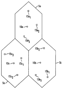
conceptualized as including a plurality of hexagonal cells 5, three of which
cells are
shown in FIG. 1 and identified as Sa, Sb and Sc. For clarity, the reference
identifier
for each feature within a particular cell will have an alphabetic character
appended
thereto to identify the feature as belonging to the particular cell, e.g.,
"a," "b," or "c."
The alphabetic character will be dropped for generic reference to cells or
features.
The aforementioned hexagonal cell shape is the classical shape for design and
analysis of wireless loop systems. It should be understood, however, that the
cells 5
are not limited to having the idealized hexagonal shape. A variety of factors,
not the
least of which is geography, will influence the desired shape of such cells
for any
particular implementation.
Within each cell 5 is a centrally-located base station 10 and a plurality of
terminals or peripheral stations 15,_". The base station 10 and each terminal
15;
includes an antenna and associated receiving and transmitting electronics.
While in
FIG. 1, only three terminals 15a,_3, 15b1_3 and lSc,_3 are shown within each
of the
respective cells Sa, Sb and Sc, it should be understood that many more of such
terminals are typically present in any given cell 5. The identifier 15; will
be used for
generic reference to a single terminal.
As those skilled in the art will recognized, the aforedescribed configuration
of
the present FWL system is very similar to mobile cellular systems. Instead of
mobile
units, the present FWL system has a plurality of fixed terminals 15,_". Such
fixed
terminals have antennas typically installed on roof tops and the like.
In preferred embodiments, each terminal antenna is directional. It will be
appreciated, however, that due to severe size and cost constraints, such
antennas may
be only moderately directional. Each terminal antenna is directed to face the
antenna
of its respective base station 10. Additional description of a preferred
embodiment of
a terminal antenna is provided later in this specification.
CA 02215607 1997-09-16
6
In conjunction with suitable electronics and methods described in more detail
later in this specification, the antenna of each base station 10 generates
several beams
that "hop" or move throughout the cell 5, receiving and sending transmissions.
As
shown in FIG. 2 for an exemplary cell Sd, the generated beams include
"receive" or
"uplink" beams 20d that receive transmission on a first frequency, f,, from
the
terminals 15d,_n. The generated beams further include an equal number of
"transmit"
or "downlink" beams 21 d for transmitting information, on a second frequency,
f2, to
the terminals 15,_". While such duplex operation is preferably implemented
using
FDM, e.g., two different frequencies, f, and f as described above, other
methods for
implementing duplex operation, among them time division duplexing (TDD), can
be
used. The term "link" will be used herein to refer, generally, to both the
uplink and
downlink communications between a base station 10 and terminal 15;.
In the exemplary illustration of FIG. 2, three uplink beams 20d,_3 and three
downlink beams 211_3 communicating with five terminals 15d6_;o are shown. In
other
embodiments, more or less simultaneously generated beams can be implemented.
It
will be appreciated that increasing the number of simultaneously generated
beams
potentially increases system capacity. Such an increase in beams, however,
also
increases interference levels. Thus, the number of beams per cell is limited
by
interference levels, and will vary due to factors, such as, for example,
geography,
concentration of terminals, building height and the like. It is expected that
the number
of simultaneously generated beams per cell will typically be in the range of
about 2 to
about 7.
As previously noted, the present invention utilizes TDM. Thus, FIG. 2 shows
the operation of the present TDM-based FWL system at one point in time. As
illustrated in FIG. 3, the time axis is divided into periodic frames 30, each
having a
plurality of time slots 35,_T. The time available in each time slot 35; is
typically
unequally apportioned to deliver a preamble 31, to provide user identification
and
syncronization information 32, to provide the "payload" 33, and to provide
guard time
34. The frames 30 have a typical duration on the order of milliseconds, while
each
time slot is significantly shorter. It will be appreciated that the time
allotted per frame
CA 02215607 1997-09-16
7
30 and per time slot 35; can vary depending on the communication requirements
of a
particular application and implementation preferences.
An uplink beam 20 receives information from a single terminal 15;, and a
downlink beam 21 transmits information to a single terminal 15; for the
duration of a
S time slot 35;. The downlink to and uplink from a particular terminal, need
not,
however, be contemporaneous. For example, FIG. 2 shows downlink beam 21 d, and
uplink beam 20d, communicating with terminal 15d6 during the same time slot.
On
the other hand, the downlink and uplink between the base station 1 Od and each
of the
terminals 1 Sd,, 1 Sdg, 1 Sd9 and 1 Sd,o are not contemporaneous.
Typically, a terminal 15 is assigned one slot 35; per time frame 30 for
receiving/transmitting. More than one slot per frame, however, either on the
same
beam or other beams, can be assigned to a single terminal 15; depending upon
communication requirements. For example, if there is a large amount of data
transmission to or from a particular terminal 15;, that terminal can be
assigned several
time slots per frame.
The total number of "active" terminals that can be supported per cell is upper
bounded by b x T, where b is the number of beams per cell and T is the number
of
time slots per frame. The actual number of active terminals 15 is usually less
than b x
T, even when demand exists, due to interference considerations. In particular,
some
time slots, depending on the location of the terminals 15 requesting service
at that
time, might be unusable due to severe interference. Moreover, such slots might
need
to remain unused in order to avoid interfering with certain active terminals.
In preferred embodiments, the frame and time slot boundaries in all the beams
20 and 21 and all the cells 5 are synchronized, or nearly synchronized.
Synchronization simplifies the control of mutual interference. Such
synchronization
presents a problem, however, since propagation time across the radius of a
cell 5 can
be larger than the guard time 34 between successive slots. In order to
maintain the
guard time, the "start of transmit" time of each terminal 15,_" must be
shifted forward
by an amount proportional to the range between the terminal 15 and the base
station
10. In this way, transmissions from terminals 15 belonging to the same cell
and time
CA 02215607 1997-09-16
g
slot can interfere with each other only during that particular time slot.
This is not the case with out-of cell interferers. Significant interference
from
other cells 5 can arrive during the full duration of the next time slot and
will typically
affect both the current and the succeeding time slot. One method for
addressing out-
s of cell interference is simply to assume that the interference is present on
both time
slots. Such an approach results in conservative estimates of interference
levels.
The present "interference limited" FWL system preferably includes power
control for reducing the spread in received signal power between short links
and long
links. A terminal having a high path loss to its base station should transmit
more
power than a terminal having a low path loss. Similarly, a base station
transmitter
transmitting toward high path loss terminals may transmit higher power than it
transmits toward lower path loss terminals. It will be appreciated that when
signal
strengths measurements are obtained for data base construction and updating,
the
correct transmit power level should be used.
In further embodiments, transmitted power can be controlled dynamically,
wherein the system compensates for the interference power existing at the
time. In
such a method, the transmitting power of all transmitters in the system is not
fixed. In
one embodiment of dynamic power control, the transmit power is determined once
before the link goes on the air, and is fixed thereafter. In other
embodiments, the
transmit power can be changed at any time based on the prevailing quality of
the link.
It should be understood that embodiments wherein transmit power is
determined once before air time and then fixed require significantly less
coordination,
calculations and information flow between the cell controllers than is
required for the
embodiments in which transmit power remains variable. In the exemplary
embodiments of the present invention described herein, transmit power is
fixed.
Power control can be implemented in a variety of ways by those skilled in the
art.
The interference level will typically change significantly from link to link
depending on the location of other links active at the time. Moreover, it is
expected
that on the average the downlinks will experience lower interference than the
uplinks.
The reason for this is that the intra-cell subset of downlink interferers,
i.e., the
CA 02215607 1997-09-16
9
interference caused by other beams emanating from the same base station 10,
are
likely to fade in correlation with the desired signal itself, since they are
all traveling on
the same path or set of paths.
As such, in some preferred embodiments, an adaptive coding and/or
modulation method is implemented to salvage time slots that are otherwise
unusable.
For example, two time slots with low rate coding can be assigned if a single
time slot
cannot provide the required performance.
Alternatively or in conjunction with adaptive coding and modulation, a form of
time diversity can be implemented by assigning multiple time slots to one
terminal 15 ;
, exploiting the fact that interference on different time slots is generated
by different
transmitters that fade independently. Such a method is particularly
advantageous
when the interference in each time slot is dominated by a single emitter,
which reaches
the receiver through a Rayleigh fading channel. In other embodiments, angle
diversity
can be used. In such a case, two beams could be used on the same time slot to
utilize
two replicas of the signal, arriving from different directions. As is
customary in
telephony, the number of installed terminals 15 significantly exceeds the
capacity of
the system, which means that a terminal 15; may be rejected when applying for
service. Given a set amount of installed terminals and the typical limitations
of a
FWL system, a TDM-based FWL system according to the present invention lowers
the
probability of such a rejection, compared to conventional systems.
The set of active terminals 15 is therefore a subset of the total population
of
terminals in a cell 5. This subset changes with time as dormant terminals
apply for,
and are granted service, and active terminals conclude their session and "hang
up".
According to the present invention, the task of controlling access to the air
and
allocating beams 20 and 21 and times slots 35,_T is performed by a cell
controller 25,
shown in FIG. 16.
The cell controller 25 is preferably implemented as a suitably-programmed
microprocessor that is located at the base station 10 of each cell 5. Among
other
functions, the cell controller 25 receives and processes applications for
service by
previously dormant terminals 15. The request can be carned over a control
channel
CA 02215607 1997-09-16
27, which can be implemented in a variety of ways known to those skilled in
the art
with small effect on system capacity. For example, the control channel 27 can
be
established on a frequency other than the frequencies f, and f utilized for
uplink and
downlink.
5 An exemplary method according to the present invention by which the cell
controller processes a service request by a terminal 15; is illustrated in
FIG. 4. As
shown in operation block 101 of FIG. 4, the cell controller 25 receives a
service
request S 1 over the control channel 27. The cell controller 25 searches for a
suitable
uplink time slot for the terminal, as indicated by operation block 103.
10 In the present context, a suitable uplink slot preferably satisfies two
conditions.
First, the interference level at the base station's receiver should be low
enough to
allow acceptable reception. Second, the requesting terminal's transmission on
that slot
should not affect other base stations that are already on the air on that slot
to such an
extent that its link's performance becomes unacceptable.
If a suitable uplink slot is found, the cell controller 25 then searches for a
suitable downlink time slot for the terminal, as noted in operation block 107.
A
suitable downlink slot similarly satisfies two conditions. First, the
interference level at
the terminal's receiver should be low enough to allow satisfactory reception.
Second,
the base station's transmission on the slot should not degrade the performance
of other
on-air terminals to the point of unacceptability. It should be understood that
there is
presently no preference for which slot is searched first.
It should be understood that the above-referenced "interference levels" and
"unacceptable performance" are system design parameters that are dependent
upon a
variety of considerations, including, without limitation, modulation scheme,
fading
environment and the like. It is within the capabilities of those skilled in
the art to
define such terms for a particular implementation of a FWL system. A more
detailed
description of an exemplary method for selecting the uplink and downlink slots
are
provided later in this specification in conjunction with the discussion of
FIG. 9.
If the cell controller 25 does not find a suitable downlink slot and a
suitable
uplink slot, the application for service is rejected, as indicated in
operation block 119.
CA 02215607 1997-09-16
11
Thus, a TDM-based FWL system according to the present invention protects
current
users from interruptions and call-drops by blocking new users, if appropriate.
This is
in contrast to CDMA-based systems, in which "blocking" takes the form of
incremental degradation of ongoing calls, leading, in some cases, to call
drops.
If an uplink and downlink slot are found, they are assigned to the terminal as
shown by operation block 111. The requesting terminal is notified of such
assignment
per operation block 115. The cell controllers of other neighboring cells are
apprised
of the new link by the cell controller 25. Communication and coordination
between
neighboring cell controllers, which is a important feature of preferred
embodiments of
the present invention, is described in more detail later in this
specification.
After the cell controller 25 allocates the downlink and uplink slots to the
requesting terminal 15;, it directs beam formers 40 to calculate the downlink
beam and
uplink beam for use during the appropriate time slots. The beam formers 40,
which
can be implemented as suitably programmed, dedicated microprocessors, "shape"
each
downlink beam 21 and each uplink beam 20 to maximize the signal-to-total-
interference ratio ("S/TI"). The resulting uplink beam 20 radiation pattern
exhibits
"notches" at angular offsets from the main lobe positioned to attenuate the
signals
received from sources of significant interference ("strong interferers"). The
resulting
downlink beam 21 radiation pattern exhibits notches at angular offsets from
the main
lobe that are positioned to attenuate the signal received by terminals 15 that
would
experience significant interference from the transmission in the absence of
such
notches. Typically, a relatively "deeper" notch will be generated to attenuate
a
relatively strong interferes, while a relatively "shallower" notch is
generated to
attenuate a relatively weaker interferes.
FIG. 5 shows an exemplary radiation pattern for a beam. The beam was
calculated to attenuate six strong interferers located at six angular offsets
from the
center of the main lobe, P 1, as indicated by the reference identifiers AZ 1 -
AZ6. The
plot in FIG. 5 shows that due to the radiation pattern of the base station's
uplink beam
20, only a very low interfering-power signal is received from the six
potential
interferers at the angular offsets AZ1- AZ6.
CA 02215607 1997-09-16
12
Further description of the beam formers 40, and exemplary methods by which
they determine the optimal uplink and downlink beams are provided later in
this
specification in conjunction with the discussion of FIGS. 11-14 and 16-18.
It was noted above that, among other activities, the cell controller
determines
whether the requesting terminal's transmission on the uplink slot affects
other base
stations already on the air. Such a determination requires that the cell
controller 25 of
a given cell 5 has access to information concerning interference levels in
links located
in other cells. Such "inter-cell" coordination or communication, wherein beam
shaping and slot assignment for a given cell are based not only on conditions
within
the given cell but also on conditions in neighboring cells allows for optimum
functioning of the system. Preferred embodiments of the present invention
utilize
inter-cell coordination.
If such inter-cell coordination is used, each cell controller 25 collects real-
time
information from "neighboring" cell controllers about activities in their
cells and
shares with them information regarding the activity in its own cell. Further
description of the collected information is described later in this
specification.
Communication between neighboring cell controllers 25 can be accomplished
using
conventional wired digital communications technology.
Neighboring cells 5 and neighboring cell controllers 25 are defined herein as
those that belong to the "cluster" of a particular cell. A neighboring cell,
such as the
cell Sa, is considered to belong to the cluster of a particular cell, such as
the cell Sc, if
transmissions originating from cell Sa can cause "significant" interference
with
reception in cell Sc, or if transmissions originating from cell Sc can cause
"significant"
interference with reception in cell Sa. In other words, a cell never
significantly affects
and is never significantly affected by radio activities in cells that do not
belong to its
cluster, typically because a sufficiently large distance separates them.
In the implementation of the present system by one skilled in the art, the
term
"significant" will require quantitative definition, such as, for example, a
particular
value of an interference power. The numerical value ultimately chosen to
define
"significant" interference results from compromises based on the design
priorities for a
CA 02215607 1997-09-16
13
particular application, e.g., capacity, signal to noise ratio, available
computing power
and the like. It is within the capabilities of those skilled in the art to
quantitatively
define the term "significant" in the context of a specific system design.
In other less preferred embodiments, the present invention can be implemented
using only "infra-cell" coordination. For embodiments utilizing infra-cell
coordination
alone, beam shaping and time-slot assignments for a given cell are based on
minimizing mutual interference within the cell without regard to conditions in
neighboring cells. For the remainder of this specification, the embodiments
described
will utilize inter-cell coordination. It should be understood, however, the
various
embodiments of the present invention may be implemented utilizing infra-cell,
rather
than inter-cell, coordination.
A portion of the data that the cell controller 25 uses to make slot assignment
decisions, and provides to the beam formers 40, shown in FIG. 16 for beam
forming
calculations, is stored in a data base 45, shown in TABLES 1 a and 1 b and
FIG. 16. In
particular, each cell controller 25 within a cluster accesses a data base 45
containing
data pertaining to the mutual interference levels between every potential link
within its
cell and every potential link within its cluster. Since the cluster of each
cell of a FWL
system according to the present invention is distinct, the data base 45
accessed by a
particular cell controller 25 is unique. The data base 45 can be implemented
as a
computer storage means located at each base station 10, or as a regional
computer
storage means serving some of the cell controllers, i.e., those within a
region, of the
FWL system.
TABLE 1 a and 1 b, below, illustrate an exemplary conceptual organization for
the data base 45. TABLE 1 a presents an overview of the data base matrix.
As previously mentioned, each cell controller 25 has its own data base. The
phrase "in-cell" refers to the cell controller's perspective. In other words,
in-cell links
refer to links within the cell controller's cell. "In-cluster" links refer to
links within
the cell controller's cluster, which include links within the cell
controller's cell.
Image
CA 02215607 1997-09-16
As shown in TABLE 1 a, the first column in the data base 45 lists all
potential
"in-cell" links. Paired with each potential in-cell link listed in the first
column is every
potential in-cluster link. Thus, in-cell link 1 is paired with every other
link in the
cluster, including nA links
5 (terminals) in cell A, nB links in cell B, through nF~ links of the final
cell of the cluster.
Likewise, each other in-cell link, 2 through n, is paired with every in-
cluster link.
TABLE lb shows exemplary entries for the illustrative pair of links depicted
in
FIG. 6. FIG. 6 shows a cell Sf and a cell Sh belonging to cell Sfs cluster.
Cell Sf
contains a link 47 between a base station lOf and a terminal 15f2o, and cell
Sh contains
10 a link 49 between a base station l Oh and a terminal 15h3. Each link
represents duplex
operation, i.e, uplink and downlink.
For the purposes of illustration, it is assumed that the data base 45 shown in
TABLE lb is the cell Sf data base. As such, link 47 is an in-cell link. The
data base
45 contains six entries for each pair of links. Four of the entries pertain to
the mutual
15 interference levels between a potential in-cell link, such as the link 47,
and potential
in-cluster links. Link 49, for example, is one of many potential in-cluster
links. The
four interference values for each pair of links are described with reference
to FIG. 6.
First, link 47 in cell Sf may experience interference due to the link 49 in
cell
Sh. More specifically, transmission from terminal 15h3 on uplink 49 may cause
interference at base station l Of on uplink 47, identified by reference
numeral 51 in
FIG. 6. Moreover, transmission from base station lOh on downlink 49 may cause
interference at terminal 15f2o on downlink 47, identified by reference numeral
53.
Secondly, link 49 in cell Sh may experience interference due to link 47 in
cell Sf. In
particular, transmission from terminal 15f2o on uplink 47 may cause
interference at
base station lOh on uplink 49, identified by reference numeral 55.
Additionally,
transmission from base station l Of on downlink 47 may cause interference at
terminal
15h3 on downlink 49, identified by reference numeral 57.
TABLE lb illustrates the data base entries for link 47 in cell f and in-
cluster
link 49. The first two entries under "Link (h, 3)," 47U and 47D, represent
values
indicative of the interference experienced in cell f on uplink 47 and downlink
47,
CA 02215607 1997-09-16
16
respectively. The next two entries, 49U and 49D, represent values indicative
of the
interference experienced in cell h on uplink 49 and downlink 49, respectively.
TABLE lb
Exemplary Data Base of Cell f
IN-CLUSTER LINKS
_______~______~~~CELL h --------------_~__~_____~~_________.
Cell Interference w/ Cell f Interference by Cell f Azi. of Term. (h, 3) Azi.
Of In-Cell
from B ~ of 11 f Terminal
46 - _ _ _ _ _
47 47U 47D 49U 49D AZH49 ZF47
48 - - _ _ _ _
1
CA 02215607 1997-09-16
17
In the preferred embodiments, the values in the data base are expressed as
normalized signal to interferer power ratios, which are defined herein as J/S.
It should
be understood that in other embodiments, the data base values can be expressed
in
other ways, for example, the received interfering signal strength and the
like.
As previously noted, a fifth and six entry is included for each link pair. The
fifth entry is the "location"of the in-cluster terminal as seen from the in-
cell base
station, e.g., azimuth of the terminal 15h3 with respect to the main lobe of
the beam of
base station l Of, represented by AZH49. The location of an in-cluster
terminal will be
used by the beam formers 40 if instructed by the cell controller 25 to "notch
out" that
particular terminal. In such an instance, the cell controller 25 retrieves
such
information from the data base 45 and provides it to the appropriate beam
formei 40.
Note that while in the data base 45, the location of the in-cluster terminal
is preferably
expressed as an "azimuth," for beam forming calculations, the location of the
in-
cluster terminal should be expressed as an "angular offset" to the main lobe
of the
beam. As such, the cell controller determines the difference between the
azimuth of
the in-cell terminal (direction of the main lobe of the beam) and the
"azimuth" of the
in-cluster terminal to express the in-cluster terminal's position as an
angular offset.
The six entry is the azimuth of the in-cell terminal as seen from its own base
station,
e.g., the azimuth of lSfZO as viewed from lOf, represented by AZF47.
Each entry in the data base 45 reflects a measured interferer to signal power
ratio. Such ratios are initially determined when a terminal is first placed in
service
and, in preferred embodiments, periodically updated. Preferably, interference
is
measured as described below and as illustrated by the exemplary methods of
FIGS. 7a
and 7b.
FIG. 7a illustrates an exemplary method for measuring down-link interference.
As indicated in operation block 201, the base station 10 of a cell 5 ("the
primary cell")
directs a down-link beam toward a terminal 15; in its cell. The beam generated
by the
base station 10 for this measurement is the "standard pattern" beam without
the
interference attenuating notches. Further, the transmit power of the beam is
adjusted
so that the power received by the terminal 15; conforms to the power control
scheme
CA 02215607 1997-09-16
18
for normal operation. Each terminal 15 within the cell's cluster measures the
received
signal strength, per operation block 203. Each of the receiving terminals
reports its
measurement to its respective cell controller 25, as indicated in operation
block 205.
Knowing the predetermined received signal power for each terminal, the cell
controller calculates the interferer to signal power ratio, if the data base
values are to
be expressed on this basis.
Each cell controller 25 reports the results of the interference measurements
to
every cell controller in its cluster. This inter-cell communication is
indicated in
operation block 207.
Decision block 209 queries whether the transmitting base station has
transmitted to each terminal 15 in its cell. If not, the next terminal is
selected, as
indicated in operation block 211, and the base station of the primary cell
transmits to
that terminal. The received signal power measurements are repeated by all
terminals
in the cluster. In this manner, the base station 10 in the primary cell
transmits to each
terminal 15 in its cell 5, and each terminal 15 in the primary cell's cluster
measures the
received signal strength during such transmission. This completes the downlink
measurements involving the base station 10 of the primary cell.
Once all downlink measurements for the cell are completed, the measurements
for another cell can begin, as indicated in operation block 213.
A preferred embodiment of a method for measuring uplink interference is
shown in FIG. 7b. As indicated in operation block 221, a terminal 15; in a
cell 5, again
the "primary cell," transmits to its base station, which directs a standard
pattern uplink
beam 20 toward that terminal. The transmit power of the terminal is adjusted
so that
the received power at the base station conforms with the power control scheme
for
normal operation. According to operation block 223, all other uplink beams 20
of the
primary cell's cluster are directed to each of the terminals 15 within the
respective
cells of such beams, terminal by terminal, during the aformentioned
transmission. In
this manner, the signal power received by an uplink beam when facing every
terminal
in its cell, due to the one transmitting terminal in the primary cell, is
measured and
recorded. Again, the standard radiation pattern of the base station antenna is
used for
CA 02215607 1997-09-16
19
measurements, and, if desired, the cell controller will express the
measurement results
as the normalized signal to interferer power ratio, i.e., interferer power to
signal power.
The cell controllers in the cluster, including the primary cell, share the
measured information with the each cell controller within their cluster, per
operation
block 225. Decision block 227 queries whether every terminal within the
primary cell
has transmitted to its base station. If not, another terminal 15 within the
primary cell
is selected to transmit, as indicated in operation block 229, and the
aforementioned
signal power measurements are repeated. Such measurements continue until each
terminal 15 within the primary cell has transmitted to the base station 10.
Another cell
then becomes the primary cell, as indicated in operation block 231, and the
interference measurements continue.
Azimuths of in-cell terminals stored in the data base 45 are preferably based
on
the actual angle of arnval of the strongest multipath replica of the desired
signal
traveling between a base station 10 and the terminal 15;, not a map derived
azimuth.
When installing a terminal antenna, it is preferable to search for the best
location and
tune the antenna for the best reception. This may be accomplished by scanning
with
the base station antenna to locate the direction of arrival of the strongest
multipath
component of the signal. Based on such measurements, and in conformity with
the
power control scheme, the transmit power for each transmitter is selected.
Note that
since uplink and downlink preferably use different transmission frequencies,
the
measurement must be carried out for both frequencies and some kind of
compromise
chosen.
For practical reasons, the azimuth of an out-of cell terminal is based on map-
derived azimuths. While it may be desirable to store measured azimuths in
preference
to map-derived azimuths, obtaining such data would significantly complicate
data
acquisition. It is believed that such an approach is not presently practical
due to the
enormity of such a task. For smaller scale systems, however, it might be
practical to
measure the actual angle of arrival of the dominant interferer signal for any
pair of a
base station and in-cluster terminal.
In preferred embodiments, a TDM-based FWL system according to the present
CA 02215607 1997-09-16
invention includes appropriate electronics and software for automatic database
updating using time slots 35 allocated for such purpose for the duration of
the
measurements.
In addition to the data base 45, each cell controller 25 maintains its own
list of
5 in-cell and in-cluster active links 46. The list 46 contains all active
links in the given
cell's cluster, the time slots allocated for the uplink and downlink, and an
estimate of
the interference-to-signal ratio (TI/S) or the inverse thereof experienced by
the uplink
receiver (located at the base station) and the downlink receiver (located at
the
terminal).
10 The cell controller 25 calculates the S/TI for links within its cell using
the data
base entries, the current list of active links in its cluster and the actual
radiation
patterns generated to support each link within its cell. As to out-of cell
active links,
the cell controller 25 relies on the other cell controllers in its cluster to
provide it with
the identity, allocated time slots and S/TIs of those links. Such inter-cell
15 communication is required since the cell controller of a given cell cannot
calculate the
S/TI for a link in another cell since each cell has a distinct cluster. The
aforementioned out-of cell (but in-cluster) information is provided to the
cell
controller 25 by input data S3;", as shown in FIG. 8.
The cell controller 25 of a particular cell takes certain actions with respect
to
20 its list 46 when advised of changes in active links anywhere in its
cluster. For
example, the cell controller 25 may be advised, via input data S2, that a
terminal
within its cell is going off the-air. In response, the cell controller deletes
the uplink
and downlink associated with the terminal from the list 46 as indicated by
operation
block S2P, recalculates the S/TI for all links in its cell as per operation
block 121, and
informs, via output data S3o"t, other cell controllers in its cluster of the
deletion and the
revised S/TI values, as indicated in operation block 127. The cell controller
may
similarly receive data input S3;~, which may contain information pertaining to
the
addition or deletion of out-of cell links. In response, the controller updates
the entries
in its list 46, as indicated in operation block S3P in FIG. 8. It then
recalculates the
S/TI of its cell links as per operation block 121, and advises the rest of the
controllers
CA 02215607 1997-09-16
21
in its cluster about the updated values per operation block 127.
When a cell controller deletes or activates a new link within its own cell, as
indicated, respectively, by operation blocks S2P and S 1 P, or when apprised
of a
change in status of an out-of cell link within its cluster via data input
S3;", a cell
controller may optionally alter any of its same-slotted uplink beams, as
indicated in
operation block 123. Such alteration is for the purpose of minimizing
interference
caused by the new link. The cell controller then recalculates the S/TI for all
same-
slotted links within its cell. A controller may likewise decide to alter its
same-slotted
downlink beams, as indicated in operation block 125. Such alteration is for
the
purpose of protecting the new link. 'The cell controller will advise, via
S3o~t, the cell
controllers in its cluster of the updated S/TI of the uplink beams, as
indicated in
operation block 127. In presently preferred embodiments, it will not, however,
advise
other cell controllers of adjustments in the S/TI of downlink beams. Such
silence is
for the purpose of limiting inter-controller data flow. It should be
understood that in
other less preferred embodiments, other cell controllers may be advised of
adjustments
in the S/TI of downlink beams.
While more readily apparent for the case in which a link is added, it is
advantageous for a cell controller to alter its beams even for the case of an
out-of cell
terminal going off the-air. In altering its beams by deleting unnecessary
notches, the
cell controller facilitates generating new notches as required, thereby
improving
system capacity.
When a cell controller calculates the S/TI (or its inverse) for links within
its
cell, it uses the normalized signal to interference measurements from the data
base.
Since, as previously described, the data base measurements are obtained using
standard radiation patterns, i.e., the beams used do not include interference
mitigating
notches, the calculated S/TI should be conservative.
As described above in conjunction with FIG. 4, when a service request is
received, the cell controller 25 allocates a receive slot on an uplink beam 20
and a
transmit slot on an downlink beam 21 if it finds suitable slots. The cell
controller 25
utilizes information from its data base 45 and list of active links 46 in
order to do so.
CA 02215607 1997-09-16
22
Having described the data base 45 and list of active links 46, an exemplary
method by
which the cell controller allocates uplink and downlink slots can now be
described.
With reference to uplink slots, the cell controller estimates the S/TI at the
base
station receiver for the proposed link on a first time slot 35;, as shown in
operation
block 131 of FIG. 9. In determining an uplink slot's suitability, the cell
controller 25
takes into account the ability of the uplink beam former 40 within its cell 5
to generate
a beam 20 with a plurality of suitably deep notches to attenuate interference
from a
small group containing the strongest interferers.
The actual achievable interferes attenuation in terms of the ratio between the
peak of the main lobe, such as the peak P 1 shown in FIG. 5, and the level of
the
radiation pattern in the direction of the interferes, such as indicated at
angular offsets
AZ 1 - AZ6, depends on many factors including, for example, the physical
configuration of the antenna, the number of interferers the beam former 40 is
trying to
attenuate, the angular location of the interferers with respect to the main
lobe, the
relative power of each interferes, and the antenna tolerances, i.e., the
extent by which
the actual structure and electronic circuitry differ from the information
known to the
corresponding beam former. In particular, phase and amplitude drifts can
significantly affect the depth and precise location of the notches produced.
Nevertheless, given the structural and electrical composition of the antenna
and the
calibration procedures, it is possible to establish a simple worst case lower
bound on
the 'notch depth" that will almost always be exceeded for a small number of
interferers located out a sector considered to be the "main lobe". For
example, a lower
bound signal to interference ratio of 35 dB might be assumed for interferers
located
out of the main lobe, while inside the main lobe, the standard pattern is
assumed.
Thus, in one embodiment, the cell controller 25 uses the aforementioned bound
to calculate the expected S/TI at the base station receiver. The expected S/TI
at the
base station receiver based on the data base can be expressed as S/ [~ J;],
where S is
the signal power and J; is the power received from the ith interferes when
standard
pattern beams are used. Notches can be implemented in certain directions in
order to
attenuate a selected group of strong interferers by using a factor ~;. ~; J;
is the
CA 02215607 1997-09-16
23
interference power remaining after the introduction of the notch. Given the
bound, p;
is easily determined for each notched out interferes. The factor ~ therefore
takes into
account the additional reduction in interferes power as defined by the bound.
For
those interferers that are not notched out, (3 = 1. The resulting TINS is thus
[~~; J; ]/S .
In an alternative embodiment, rather than using an assumed notch depth, the
cell controller 25 calculates the radiation pattern using an exemplary method
described
later in this specification. The exemplary method determines an optimum
"weighting
vector" required to generate the beam and also calculates the S/TI.
Preferably, the cell
controller 25 should allow some margin to account for electrical and
mechanical errors
that limit the achieveable "depth" of the calculated notches.
In decision block 133, the cell controller queries whether the revised S/TI
for
the base station receiver is greater than or equal to a threshold S/TI, i.e.,
the minimum
S/TI for "acceptable" reception. If the new S/TI is less than the threshold
value, the
cell controller checks to see if all uplink slots have been checked, per
decision block
134. If all slots have been checked, and none have been found acceptable per
block
135, the request is rejected. If not, then the calculation is repeated for
another slot, as
indicated in operation block 136.
If the calculated S/TI is equal to or greater to the threshold value, then the
cell
controller determines, in operation block 137, if adding the link affects
other base
stations that are already on-the-air on that slot to such an extent that the
reception of at
least one other link becomes unacceptable. This is accomplished by
recalculating the
S/TI for all active uplinks in the cluster. To perform this calculation, the
cell controller
retrieves the S/TI of each of such active links from its list 46 and
determiners the
effect of the additional interference, based on the corresponding data base
entry. The
25 new value of S/TI resulting from the addition of the considered new link
is:
1 = expected S/TI after the new link is added
[~ J; ]/S + J~ / S
If the calculated S/TI of any of the on-the-air links degrade beyond the point
of
CA 02215607 1997-09-16
24
acceptability, the time slot is rejected.
In considering the effect of the added terminal 15 on other terminals, the
cell
controller 25 does not rely on the ability of other base stations 10 to
generate radiation
pattern notches intended to minimize the interfering effect of the terminal
15;. The
reason for this is that other cell controllers cannot respond to such a
request in "real
time." Thus, the cell controller 25 will approve a receive slot only if all of
the out-of
cell active uplinks using that slot can sustain the additional expected
interference
before adjusting their current beam. After notification of a new link, the
cell
controllers of affected cells will, however, preferably reduce their received
interference by altering their uplink beams 20 as previously noted in
conjunction with
the discussion of FIG. 8.
Decision block 138 queries if the S/TI for all existing links is equal to or
greater than a threshold value. If so, an uplink slot is found, per block 139.
If the
S/TI for one or more links is less than the threshold, then the time slot
under
consideration is rejected. If all time slots have been considered, then the
request for
service is denied. If additional time slots remain to be checked, the next
slot is
selected per operation block 136 and the S/TI for the time slot is calculated
and
processed as previously described.
The cell controller 25 performs essentially the same steps when considering a
downlink slot. In operation block 131, the S/TI of the terminal receiver is
calculated
for a candidate time slot. The interference at the terminal receiver will be
caused by
other base stations. The cell controller will not rely on the ability of the
controllers of
such other base stations to alter their downlink beams by adding a notch for
the benefit
of the requesting terminal. As such, the calculated S/TI is based on the data
base.
If the calculated S/TI at the receiver for the candidate slot is greater than
or
equal to a threshold value, the cell controller fiuther verifies that all of
the terminals 15
in its cluster currently receiving on that slot can sustain the additional
interference of
the base station's transmission. For this calculation, the cell controller 25
calculates
the affected S/TI values using values from the data base 45. If necessary, the
cell
controller can rely on the ability of its beam formers to generate a number of
notches,
CA 02215607 1997-09-16
the depth of which can be conservatively estimated using a bound.
All calculations and comparisons are repeated until a suitable pair of slots
are
found or until all time slots have been checked and no suitable pair of slots
are found.
If the cell controller 25 finds a pair of slots satisfying the requirements,
it will direct
5 the beam formers 40 to generate the receive and transmit beams during the
selected
slots. Otherwise the requesting terminal will be denied access.
Beam forming has been referenced briefly a number of times above. A more
detailed description of beam forming is now provided. It will be appreciated
that the
beam formers 40 must complete their calculations rapidly to avoid system
delays. A
10 dedicated powerful microprocessor may be required for each beam former.
The cell controller 25 provides each beam former 40 with specific information
required for beam forming. More particularly, to calculate the radiation
pattern for a
downlink beam 21 for transmission to a terminal 15;, a beam former 40 is
provided
with:
15 (i) the azimuth of the terminal 15;;
(ii) a short list, which can be empty, of phase offsets (measured with
reference to the main lobe) to avoid; and
(iii) a quantity representing the relative importance of transmission
suppression on each phase offset.
20 To calculate the radiation pattern for an uplink beam 20 for receiving a
transmission
from terminal 15;, a beam former 40 is provided with:
(i) the azimuth of the terminal 15;;
(ii) a short list, which can be empty, of phase offsets to "null out;" and
(iii) the anticipated power of every interferer in the short list, which is
25 obtained from the data base 45.
Both radiation pattern calculations can be calculated according to the
exemplary methods described later in this specification. The calculations are
very
similar, a difference being that, for the downlink, the "quantity representing
the
relative importance of transmission suppression on each phase offset" must
first be
expressed as a "virtual interferer power" through a simple monotonically
increasing
CA 02215607 1997-09-16
26
conversion function. For example, consider link A and link B, both of which
appear in
the short list provided to the downlink beamformer 40. Reception on link A is
marginal, while reception on link B is better, i.e., a higher S/TI ratio. The
virtual
interferer power corresponding to link A should result in a relatively deeper
notch
being formed in the direction of link A than the notch formed in the direction
of link
B. It should be understood that such a function is dependent upon the specific
configuration of the base station antenna, among other considerations, and is
selected
by the antenna designer. Selection of such a function is within the
capabilities of those
skilled in the art.
The result of the calculations is the weighting vector, W. The calculated
vector
is then stored and reused during the same time slot 35 in following frames 30.
Note
that a notch resulting from the beam forming calculations provides a S/TI at
the
receiver that is greater than or equal to the S/TI estimated during slot
allocation using
the lower bound signal to interference value.
Beam forming operations are described in more detail in conjunction with
FIGS. 11 - 14. To facilitate the description, the preferred configuration of
the base
station antenna will be provided. The terminal antenna is described, as well.
It is desirable for the antenna located at each terminal 15,_N to be small,
inexpensive and easy to install. Notwithstanding the desire for simplicity, in
some
embodiments, the terminal antenna is mechanically adjustable in such a way
that a
radiation dip can be realized in one or two directions. The reason for this is
that a
large portion of the interference power typically comes from a single source.
Interference may thus be attenuated, albeit crudely, by an installation-time
adjustment
based on the geographic location of the base station that is expected to be
the main
source or object of interference.
In one embodiment, the terminal antenna is fabricated from two parts such that
the spacing between the parts can be mechanically adjusted. Such an antenna
will
have a variable width main lobe bordering a notch that can be mechanically
adjusted
over a limited angular range. Other physical configurations for achieving the
aforementioned objective will occur to those skilled in the art.
CA 02215607 1997-09-16
27
The base station's antenna is considerably more complex than the terminal
antenna. T'he base station's antenna is a phased array antenna capable of
simultaneously generating N transmit beams and N receive beams. The transmit
and
receive beams are independently steerable in any direction in the horizontal
plane
under the control of a beam former 40. When steered in azimuth, a beam
maintains an
approximately fixed beamwidth in the vertical plane. Preferably, the beamwidth
ranges from 15 to 20 degrees at the 3dB points. In areas that are flat,
narrower vertical
beams can advantageously be used.
The antenna of the base station 10 is preferably configured as a planar
circular
array having vertically-placed radiating elements attached to the surface of a
virtual
vertical cylinder of radius R. The centers of such radiators are aligned
thereby
defining a ring in the horizontal plane. Each radiating element can be, for
example, a
vertical colinear array of some basic radiator. An exemplary radiation pattern
of a
radiating element in the horizontal plane is shown in FIG. 10. The pattern
shown in
FIG. 10 is the measured pattern of a vertical array of four patch antennas.
Antenna
size is dictated, as a practical matter, by frequency, real estate and cost
considerations.
Configurations other than a planar circular array can suitably be used.
In order to take full advantage of the directivity of individual radiators and
minimize the effects that might otherwise result from hardware and harnesses
that may
be installed inside the cylindrical volume, only part of the total number of
radiators are
active to generate the beam. The active radiators occupy a sector facing the
direction
of the desired beam, and are distributed approximately equally on either side
of a line
crossing the center of the circular structure pointing toward the desired
direction of the
main lobe. The sector including the active radiators is referred to herein as
"the active
sector" of the beam. The angular width, a, of the active sector is a free
design
parameter that should be optimized for the selected radiation pattern of the
individual
radiator and the number of radiators in the cylindrical array.
An exemplary method for generating the "standard pattern" of an uplink beam
is described below. As indicated in operation block 141 of FIG. 1 l, a
weighting
vector, W, is generated that optimizes the S/TI at the antenna output. A
detailed
CA 02215607 1997-09-16
28
description of the calculation method is provided later in this specification.
For the
calculations, it is assumed that a base station 10 antenna is located at the
center of a
large circle placed in a horizontal plane, as shown in FIG. 12. A large
number, I, of
equal power noise sources 301 are assumed to be equally spaced along the
circumference of the circle, and such sources cover the complete circumference
except
for a clear window region 303 that is free of noise sources and has one signal
source
305, which is the desired signal, located at the center of the region 303. The
width of
the clear window 303 is a design parameter to be optimized. Such optimization
can be
performed, for example, by using the exemplary calculation method for
determining
the optimal weighting vector described below for several values of window
width and
choosing the one yields the best S/TI.
As indicated in operation block 143 of FIG. 1 l, the optimal weighting vector
is
stored and later used in the same time slots 35 in following frames 30.
According to
operation block 147, the S/TI is calculated and provided to the cell
controller 25, and,
ultimately, to other cell controllers in the cluster. Meanwhile, beam forming
electronics, described in conjunction with FIGS. 15- 17, generate the beam,
per
operation block 149. FIG. 13 provides a conceptual illustration of how the
weighting
vector W is used to generate a beam.
As shown in FIG. 13, signals S, - Sk received by K radiating antenna elements
307 are multiplied, using multipliers 423, by the corresponding component of
the
vector W and then summed to produce a radiation pattern that optimizes the
S/TI at
the antenna output.
Generating the optimum S/TI as described above results in the "standard"
radiation pattern previously mentioned in conjunction with measurements for
the data
base 45. Beams having a standard radiation pattern address the large number of
background interferers 301 without taking into account the location and power
of any
interferes in particular. In a further preferred embodiment, if the location
and relative
power of a group of especially strong interferers are known, they can be
considered in
addition to the large number of equal power interference sources 301 in
deriving the
optimal weighting vector W. Such specific interferers are illustrated in FIG.
14.
CA 02215607 1997-09-16
29
Essentially the same method is followed to generate the weighting vector W
for the downlink beams 21. As previously described, the method differs in that
a
virtual signal source is placed in the desired transmission direction and
virtual
interferers are placed in the directions in which interference generation is
to be
avoided. The power of the virtual interferers reflects the importance assigned
to
minimizing transmission in those directions.
In response to locating virtual interferers in certain directions, a beam
former
40 generates a beam having notches in those directions. The depth of each
notch
reflects the power of the virtual interferer. It should be understood that
while in theory
notch depth (expressed in dB with reference to the beam's main lobe) is
unlimited, in
practice, notch depth is limited. In particular, notch depth is limited by the
propagation irregularities such as multipath propagation, reflections from
conducting
objects, and the like. Also, as previously mentioned, notch depth is limited
by antenna
tolerances.
After determining the optimal W, the S/TI is calculated. An exemplary
method for determining the weighting vector W in a way that optimizes the S/TI
at the
antenna output now follows.
The radiation pattern of each radiator in the horizontal plane is g(~), where
the
array consists of K radiators arranged along a circular section. The amplitude
of the
signal received by radiator k from a source located in the horizontal plane at
angle ~ is
proportional to the quantity Sk(~), where the phase reference is the center of
the circle
ofradius R:
Sk(~) - g(~-~>JExP{j2'~(R/~,)Cos(~h-fik ) } A1
The signal voltage received by the complete array will be:
x
v = ~ wksk(o) A2
k~ I
where Wk is the complex weight of the kth radiator.
This inner product can be written as a multiplication of two column vectors:
VS = W'S(~) A3
CA 02215607 1997-09-16
where W' indicates W transposed.
A small number of dominant interferers are assumed to exist, whose angular
location and field intensity in the area where the antenna is located are
precisely
known. In addition to those dominant interferers, a large number of
"background"
5 interferers exsists. The background interferers are not individually
accounted for.
Rather, they are replaced, for beam synthesis purposes, with uniformly spaced
equal
power interference sources. All interferers are assumed uncorrelated.
The total number of interferers is represented by I. Then the noise voltage
received by the kth radiator is:
vn(k) = W~En,Sk(~~) A4
,.1
10 And the total interference voltage is:
K K l
V = E Vn(k) = E WkEn,S~(~~) AS
1~1 K~1 i-I
The expected interference power is:
PN =E~Iu~I2~
x i K _ r
= E EWkEnS,~(~h;) ~ EW,EnS~(~;)~ A6
m a.~ ~a ;.i
Where the "bar", e.g., , indicates the complex conjugate.
When the interference sources are uncorrelated:
E{n n~} =n;z8;r A7
15 the interference power reduces to:
CA 02215607 1997-09-16
31
x x _i _
Pn = E EWkW,En;2Sk(~l)S~(~l) A8
bl 1.1 i~1
This may be written in a compact matrix form:
P~ = W*MW A9
(W* is W conjugate and transpose) where the elements of M are given by:
m~, = En~2Sk(~i)S~(~;) AIO
i.,
The signal power to interference power ratio may then be expressed as:
SlTI =
~ ~'~S(~)~2 All
W'MW
S/TI reaches maximum when the weighting vector is chosen as:
W~ = M~'S(~h) A12
Finding the optimal weight vector requires calculating the terms of a K by K
matrix
and then inverting it. If, however, only a single interferer is being added or
dropped,
the matrix can be modified using a "fast" algorithm, described later in this
specification.
Once WoPt has been found, the radiation pattern is calculated from:
F(~) = S'(~)Wo~ A13
The S/TI obtained when using WoPt can be calculated:
Since:
MYt'9x = S(~h)
CA 02215607 1997-09-16
32
Iw~ S(~)IZ (w~rs(~))(w~(~)) ,
SlTI = ~' - ~ = w~rS(~) A14
w~s(~) w~.s(~)
= F(~>
F(~) is a power ratio, and therefore should be converted to dB with:
l OLog(F(~)).
In this application, -8 s ~ s 8 where 28 is the angular separation between two
radiators. When there is a need to steer a beam out of this limited range, a
new active
range is selected, i.e., some (possibly all) radiators are replaced by others.
The field generated by the array in direction (~,A) is given by:
K
Es(~,e) = E wksk(~,e) Als
where:
Sk(~,6) = g(~-~k,6) exp{j2~c(R/~.)Cos(a,~} A16
and:
Cos(a,~ = Sin(6)Cos(~-~,~ A17
Substituting A 16 & A 17 into A 15
K
Ef(~h,6)= E wkg(~-~~,8)exp{j2n(Rl~.)Cos(~-~~)Sin(6)} A18
m
The directivity of the antenna in direction (~,6) can be calculated by
determining:
D - reception from direction(~h,A)
average reception intensity
IE(~~8)IZ
2a R
v4~ ~d~ y Eg(~,e) I Zsineae
0 0
CA 02215607 1997-09-16
33
See, Sureau et al., "Sidelobe Control in Cylindrical Arrays," IEEE Trans. Ant.
Prop.,
Vol. AP-30, no. 5, 1982; Applebaum, "Adaptive Arrays," IEEE Trans. Ant. Prop.,
Vol. AP-24, no. 5, 1976.
EXAMPLE
Assume that the antenna array contains 3K = 96 elements spaced 0.55.1 apart
around a horizontal circle. A beam is generated by activating only one third
of such
elements. The 32 activated elements are located on a 120 degrees "horseshoe"
facing
the the location of the desired signal. 'The signal source is at ~=0.
The kth antenna element is therefore located at:
2~(k-K/2-0.5)/(3K) radians A19
The radius, R, of the cylinder supporting the antenna elements is R=8.4033,.
The
amount of calculations can be limited by dividing the interferers to two
groups. The
first group represents a small number of dominant interferers whose precise
location
and intensity are known. Such dominant interferers are accounted for on an
individual
basis. The second group of interferers is considered to be a large number of
equal
power interferers placed uniformly around the antenna keeping a "clear window"
of w
radians. All interferers are considered uncorrelated. All the interferers
generate the
same noise power, rh, which is arbitrarily chosen as 1. The angle between any
two
interferers is: (2~-w)/I radians.
The ith interferer is located at:
w/2+(2n-w)(i-0.5)/I A20
The "clear window" is generated by setting the power of the two interferers on
either
side of ~=0 to 0. w is therefore equal to 2(2n/100).
Substituting equations A15 and A16 into equation 1:
Sk(~h;) =g(w/2+(i-0.5)(2~c-w)/I-2~(k-K/2-0.5)/(3K))
exp{j2~(R/~.)Cos(w/2+(i-0.5)(2-w)/I- 2~(k-16.5)/(3K))} A21
CA 02215607 1997-09-16
34
For the chosen parameters, the radiation pattern obtained with I >100 is
essentially
independent of I. Therefore I is chosen to be 100.
The function g(~) must be defined. For the present example, an analytic
approximation to the measured radiation pattern of a "Patch Antenna" is used:
g(~h) = Cos4(~/2)+0.17Cos4((~-~)/2)-0.0568 A22
Substituting equation A22 into A21, and A21 into A10, the covariance matrix M
is
obtained. Wop~ and the electric field F(~) are then calculated from equation
A13.
To find the optimal weighting vector for the case where a group of N strong
interferers, each with interfering power n~2 ; j=1,....,N are known to exist
at given
angular locations, the corresponding terms are added to the elements of the
matrix M
(equation A10). The calculation proceeds according to the previously described
method. The resulting radiation pattern is shown in FIG. 5
As long as the power of the strong interferers is not higher than the combined
power of the interferers representing the background noise, the modified
radiation
pattern remains very close to the original (i.e., with no strong interferers)
except at the
"immediate vicinity" of a interferer, where a sharp notch appears.
FIG. 5 shows the radiation pattern generated by the exemplary algorithm when
98 "weak" interferers ( 100 minus the 2 that were eliminated in order to
generate the
clear window) and in addition six "strong", equal power, interferers located
as shown
are specified. FIG. 14 shows the S/TI ratio when the power of the strong
interferers is
the independent variable. The signal power was first set in the absence of the
strong
interferers so that the resulting S/TI ratio obtained is 30 dB. It can be seen
that when
the antenna beam is adjusted to compensate for the increasing power of the
"strong"
interferers, as indicated by reference numeral 90, the S/TI ratio degrades
very slowly,
while when W is held fixed indicating no adjustment, as indicated by reference
number 94, the S/TI degrades rapidly.
Returning now to the issue of calculating the vector W. Since, the set of
significant interferers for a given link can change relatively often, W must
be
CA 02215607 1997-09-16
recalculated frequently. Thus, in preferred embodiments, a "short cut" or
"fast"
method for recalculating an existing beam whenever a single interferes is
added or
deleted is utilized. An exemplary embodiment of such a fast method is
described
below.
5 As previously described, e.g., equation A12, calculating Wopt involves
inverting the matrix M, which is a square KxK matrix. If K is large, i.e.,
there are
many radiators, this is a calculation intensive task. Once the matrix M is
known,
however, modifying it to add or delete a single interferes can be done using a
simplified method. The short-cut method uses the following theorem:
10 If a matrix A can be written as:
A=B+aUV'
where: U & V are column matrices, then:
A-' = B'' - ~, a YZ'
where:
15 Y = B-'U ; Z' = V'B-' ; and ~. = 1/(1+aZ'U)
Based on the previous derivation the matrix M can be written as:
N
M=M +En~2conj(S(~~))S'(~~)
/-1
where: S(~~) is the column vector: [S,(~~) SZ(~~) ..... SK(~~)]' ;
conj(S) is the complex conjugate of S, and S'(~) is the transpose of S(~h).
N is the number of additional interferers to be "notched" out, ~~ with j=1,
....,
20 N is their location and n~z is their corresponding power. M is the modified
matrix and M~~ is the
matrix used in the original interference environment.
As before:
W = M-' conj(S(~))
CA 02215607 1997-09-16
36
Therefore, addition or deletion of the j"' interferes means that the Matrix M
should be
modified as follows:
M~''~ = M~k-'> + ~k n~2conj(S(fi~)) S'(~~)
where: M~''~ is the matrix used after the k'" step (i.e., following the
inclusion/deletion
of the j'" interferes);
M~''-'~ is the matrix used in the (k-1)'~ step (i.e., the original matrix);
~k = +1 if adding an interferes; ~k = -1 if deleting an interferes.
The new M matrix can be inverted as follows:
M~k>-' = M~k~'~~' - .IaYZ'
where: Y = M~''-'>-'U ; U=conj(S(~h~))
Z~ = V~Mcx_m . V=S~O )
i
~, = 1/(1+aZ'U) ; a=~i''n~2
and:
W'' = M~k~-'conj(S(0))
This method requires around 3K2 + 2K multiplies.
In a further preferred embodiment, the fast method can be further shortened by
the following substitutions:
Since: V = conj(U'); M = conj(M') and Z = conj(Y'),
the optimal vector can be calculated directly by determining the followiing
quantities:
1. a = ~3nz
2. Y = M~''''~''U
3. ~, = 1/{1+a conj(Y')U}
4. M~''~ -' = M~''-' ~ -' - ~, a Yconj (Y' )
5. W~''~ = W~''-'~ _ ~.ayconj(Y')conj(S(0))
where: W~''> is the new optimal weighing vector to be used in step k and W~''-
'~ is the
optimal vector used in step k-1.
This method requires around 2K2+4K multiplies and 2K2+3K additions. In
comparison, the direct method of calculating the M matrix and inverting it to
find the
optimal W requires around KZ+K+O(K3) multiplies.
Block diagrams of some of the important signal receiving, beam generating
CA 02215607 1997-09-16
37
and signal transmitting electronics of a base station 10 are shown in FIGS. 16-
18. It
should be understood that such block diagrams omit many components that are
not
essential for understanding the invention, e.g., filters, IF amplifiers and
the like. It will
be appreciated that illustrations are provided to facilitate understanding of
the
invention, not to limit its scope.
FIG. 16 illustrates exemplary base station transmit (downlink) electronics for
a
multiple beam system according to the present invention. A number, N, of
transmit
modems 401, preferably operating at IF frequency, each provide a signal, S;,
intended
for transmission to a terminal 15. The number N is the number of transmit
(downlink) beams DB 1 - DBN. The signals S,_N are provided, one each, to N
power
dividers 403. The power dividers 403 divide each signal S; into K channels G.
The N groups of K channels C~ are sent to N banks of K multipliers 405. The
multipliers multiply each channel C~ by the appropriate one of K sine waves
generated
by N phase and amplitude controllers 429. The amplitude and phase of each sine
wave is dictated by the appropriate component of the weighting vector W, which
is
calculated by one of the downlink beam formers 40a under the control of the
cell
controller 25.
The resultant K channels CO~ for each beam are sent to a downlink switching
and summing matrix 407, which, under the control of the cell controller 25,
routes
each of the groups of K channels CO1 - COk into K contiguous possibly
overlapping
radiator channels CRS - CRk. All the radiator channels are fed to an up-
converter 408.
The up-converter 408 up-converts the output of the switching and summing
matrix
407 to the transmit frequency. The up-converter comprises a bank of mixers
409, a
power divider 433 and a local oscillator or synthesizer 431. Note that a
common
synthesizer 431 is used.
The up-converted radiator channels are fed to a bank of M power amplifiers
411, one per radiator, where M is the total number of radiators comprising the
phased
array antenna. The amplified channels are sent to a bank of M diplexers 413,
one per
antenna radiator. The diplexers route the channels to the K active radiators
415.
FIG. 17 illustrates exemplary receive (uplink) electronics for a multiple beam
CA 02215607 1997-09-16
38
system according to the present invention. The signals received by the
radiators 415
pass through the bank of diplexers 413 to a bank of M low noise amplifiers 417
and
then to a down converter 418. The down-converter 418 down-converts the
frequency
of the received signals for processing in the switching and dividing matrix.
Like the
up-converter 408, the down-converter comprises a bank of mixers 419, a power
divider 437 and a local oscillator or synthesizer 435. Again, the synthesizer
435 is
common.
The uplink switching and dividing matrix 421, under the control of the cell
controller 25, routes the signals from N groups of K contiguous radiators to
the
appropriate beam electronics. N banks of K multipliers each multiply the K
signals
for each beam by the appropriate one of K sine waves generated by N phase and
amplitude controllers 439. The amplitude and phase of each sine wave is
dictated by
the appropriate component of the weighting vector W, which is calculated by
one of
the uplink beam formers 40b under the control of the cell controller 25.
The K signals comprising an uplink beam UB 1 - UBN are fed to a power
combiner 425, which feeds the combined signal to one of N receive modems 427.
FIG. 18 shows an exemplary architecture of the phase and amplitude
controllers. Each phase and amplitude controller 429, 439 includes K direct
digital
synthesizers (DDSs) 441. Each DDS 441 generates a sine wave, the phase and
amplitude of which is controlled by an appropriate one of K signals BFS,_K for
a given
uplink or downlink beam generated by the respective beam formers 40b, 40a. The
bank of K DDSs is clocked by a common clock line, CL, and reset by a common
reset
line, RL. Bandpass filters 443 ensure that the signal sent to the mixers 423
are clean
of undesired spurious. Amplifiers 445 amplify the signals produced by the
DDSs.
441.
Although a number of specific embodiments of this invention have been shown
and described herein, it is to be understood that these embodiments are merely
illustrative of the many possible specific arrangements that can be devised in
application of the principles of the invention. Numerous and varied other
arrangements can be devised in accordance with these principles by those of
ordinary
CA 02215607 1997-09-16
39
skill in the art without departing from the scope and spirit of the invention.
For instance, other known methodologies can be used in conjunction with the
present "open loop" method. One example of this is using an "adaptive
beamforming"
in an attempt to improve the S/TI of a received signal once the signal is
already on-
the-air. An adaptive beam may be implemented by using a closed-loop adaptation
algorithm driven by the designated receiver of each receive beam. Such closed-
loop
adaptation algorithms are well known to those skilled in the art. Such a
method might
avoid the need for frequent calibrations of the base station's antenna system
in order to
counter possible drifts in the electronic circuitry supporting each individual
radiator.
Another feature of such a embodiment may be the ability of an adaptive beam to
track
temporal changes of links parameters.