Note: Descriptions are shown in the official language in which they were submitted.
CA 02215764 1997-09-16
WO 96!35314 ~~ PCT/EP95/01649
Process for controlling a programmable or program-controlled hearing aid
for its in-situ fitting adjustment
The invention relates to a process for controlling a programmable or program-
controllable hearing aid for in-situ adjustment of said hearing aid to the
optimum gain in one or more frequency bands, with due consideration of any
possible acoustical feedback, as per the preamble of claim 1 .
It is well known that with hearing instruments, be it with BTE hearing aids
that are connected to the ear canal by means of a small-diameter plastic
tubing and an earmold, or with an ITE hearing aid inserted deeply into the
ear canal with its earmold or otoplastic, acoustic feedback is possible from
the residual cavity between the earmold and the timpc~nic membrane to the
microphone, either by a less than perfect fit of the earmold in the ear canal
or by a small venting tubing provided for pressure relief, or both.
This has for example been described in "HEARING INSTRUMENTS, Vol. 42,
Nr. 9 1991, pages 24, 26" .
Additional ly, US-A 5.259.033 and its European counterpart EP 0 415 677 A2
disclose a hearing aid with an electric or electronic compensation for
acoustic
feedback. Particularly, the hearing aid includes a controllable filter in an
electrical feedback path, the characteristics of which are calculated and
controlled to model the acoustic coupling between the earphone and the
microphone of the hearing aid using a correlation method.
A noise signal is injected into the electrical circuit of the hearing aid and
is
used for adapting the filter characteristics to accommodate changes in the
acoustic coupling.
CA 02215764 1999-12-21
-2-
The coefficients for controlling the filter characteristics are derived by a
correlation
circuit.
Furthermore the WO 93/20668, published with abstract and claims in English and
drawings only discloses in principle the same circuitry, further including a
digital
circuit which carries out a statistical evaluation of the filter coefficients
in a correlation
circuit and changes the feedback function adaptively. The compensation covers
the
entire audible frequency range.
1 o WO-A-9005437 and US-A 4.185.168 are both further examples of automatic
systems for reducing feedback problems, when they occur during normal
operation.
For this purpose simply additional complex circuitry is used in the hearing
aid and
additional filters are required, which will effect the entire frequency band
where and
when they are activated.
Many of the more modern hearing aids are capable of varying the gain in order
to
adjust to the actual sound environment and the actual hearing loss. This can
be
done in one or more frequency bands.
Most hearing losses are characterized by "recruitment". In other words, weak
sounds cannot be detected and powerful sounds are heard as normal hearing
people
would hear them. Traditionally, these hearing losses are fitted with hearing
aids
having a fixed gain. This gain is typically too low at weak sound levels and
too high
at powerful sound levels.
To compensate more ideally for this kind of hearing loss the hearing aid
should have
high gain at weak sounds and zero or low gain at powerful sounds. Such types
of
hearing aids typically have high gain in quiet environments which increases
the risk
of acoustic feedback. The gain at which feedback occurs depends primarily on
the
3 0 quality and shape of the earmold.
CA 02215764 1999-12-21
- 2a -
However, until now the most common way to solve the problem of an
unsatisfactory
earmold that caused unacceptable acoustic feedback was to throw it away and
have
a new one made. This means that no one ever knew what was wrong with it and
exactly how bad the earmold was.
CA 02215764 1997-09-16
WO 96/35314 PCT/EP95/01649
-3-
Obviously poor earmolds cause considerable problems in case of severe hearing
losses and the then necessary high gains. In order to avoid feedback with an
earmold that cannot be made better the hard-of-hearing has the only choice to
turn down the volume control for the entire frequency range.
General lye there are more and more programmable, program-control table or
programmed hearing aids most of which could be reprogrammed for one or more
frequency bands or channels by an external programming unit for one or more
transmission characteristics and, mostly, adapted at the same time to the
actual
hearing loss of the wearer.
Unfortunately, when in-situ programming and fitting of a hearing aid of this
type, there are presently no instruments to detect any acoustic feedback com-
bined with an automatic testing process to adjust the hearing aid to an
insertion
gain that avoids acoustical feedback and / or indicates whether for the ampli-
ficati~ / gain required for a specific hearing loss the earmold is fitting
well
enough in the ear canal . This would have the result that at this maxim~n gain
for the specific hearing threshold level- no acoustic feedback would occur,
indicating whether this earmold has the required quality of fitting inside the
ear canal for the specific gain required.
Generally speaking it is a main object of the present invention to create a
novel process with the intention to provide a solution for automatic measuring
of the hearing threshold level (HTL) in one or more frequency bands for a
specific hearing instrument including the earmold and to provide for an auto-
matic adjustment of the hearing instrument to avoid possible acoustic feedback
at the required or possible maximum gain, and finally to provide for the
optimization of the parameter set for said final fitting with due
consideration
- of the acoustical feedback and the hearing impairment or the hearing loss
of the wearer.
CA 02215764 1999-12-21
- 4 -
Also last, but not least to provide for automatic checking for the required
quality of
the earmold and to give a warning in case the quality of the earmold is
insufficient to
sustain the required gain of the hearing aid for the particular impairment,
without
feedback to occur.
These objects are achieved by the new process in accordance with the present
invention by setting the control parameter set of the signal processor
initially to an
input/output response function with a maximum gain equal to the maximum gain
of
the ideal input/output response function and operating the hearing aid in-situ
in
1o accordance with said initial ideal input/output response function while
monitoring said
hearing aid for the occurrence of any acoustic feedback, and if no noticeable
feedback is detected setting said initial parameter set for said ideal
input/output
response function into said hearing aid, and if noticeable acoustic feedback
is
detected reducing the maximum gain over at least one of said frequency bands
while
leaving unchanged with respect to said initial parameter set the gain in any
other
frequency band, to thereby obtain an adjusted input/output response function
for at
least said one frequency band.
A particular improvement of the invention consists in that by the continued or
2 o periodic monitoring of the hearing aid for continued feedback, by the
control and
communication unit in combination with the programming unit, and by adjusting
the
maximum gain to a value smaller than the calculated maximum gain and by
monitoring again for any remaining feedback and reducing the maximum gain
until
no further feedback is detected, it is possible to set the actual maximum gain
to a
value that is equal to the maximum gain that is possible without feedback, and
to
store the corresponding parameter set in the hearing aid as a final setting.
Furthermore, it is of great advantage that, if the control and communication
unit continues to detect feedback after reaching a predefined lowest level of
3 o amplification or gain in one or more frequency bands, the fitting process
CA 02215764 1997-09-16
WO 96/35314 PCT/EP95/01649
-5-
is terminated by storing the results in the programming unit as an indication
of the poor quality of the earmold.
Finally, it is important that by simultaneous checking of the prevalent
background
noise level, it is ascertained that the background noise level is well below
the
level where the maximum gain appears in order to stop the process in case the
background level approaches or exceeds the volume indicated in one or more
frequency bands.
The invention will now be described with respect to a preferred embodiment of
the inventive process and in conjunction with the accompanying drawings.
In the drawings
Fig. 1 shows schematically a hearing instrument including pro-
gramming means;
Fig. 2 schematically a diagram of the hearing perception function
and the impaired hearing function of the recruitment type;
Fig. 3 schematically an ideal input/output response of a hearing
aid of the type used for the invention;
Fig. 4 schematically a flow diagram of the process in accordance
with the inventi~;
Fig. 5 schematically an illustration of the input/output response
used during the test procedure and
Fig. 6 shows schematically the resulting input~output response
after the test procedure is completed.
CA 02215764 1997-09-16
WO 96/35314 PCT/EP95/01649
-6-
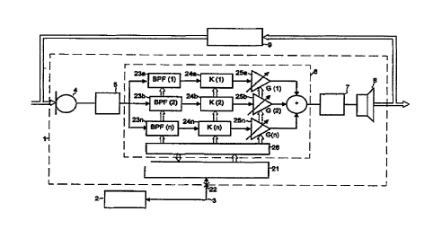
In Fig. 1, a hearing instrument or wearable hearing aid 1 is shown and is
connected to a programming unit 2 by means of a two-way communication
link 3. The hearing aid 1 comprises f.i. a microphone 4, an A/D-converter
5, a digital signal processor 6, a D/A-converter 7 and a speaker 8.
Principally, there could be more than one microphone 4 and/or more than
one speaker 8.
The signal processor 6 in its digital configuration could, f.i. consist of one
channel or a number of channels, for one frequency range or for a number
of frequency bands respectively.
Obviously the entire hearing aid could also contain correspondingly designed
analog circuits.
Whether the hearing aid is an ITE instrument to be inserted into the ear canal
or a BTE instrument to be connected by means of a sound-conducting tubing
with an earmold inserted into the ear canal, there is always the possibility
of acoustical feedback. This feedback path is shown as an impedance/ad-
mittance 9.
It has to be remarked here that such feedback in some cases of severe hearing
loss would be rather difficult to control or to avoid.
Figs. 2 to 6 will now be used to explain the approach taken for solving the
problem as indicated above, namely to provide a simple process to measure
the quality of an eannold during the automatic fitting process and to design
a process to adjust the hearing aid with the actual .limitations of the
eannold.
In other word;, the invention provides a novel method to determine if the
actual earmold has a sufficiently high quality of fitting inside the ear canal
to match the actual hearing loss in one or more frequency bands.
CA 02215764 1999-12-21
J
Fig. 2 shows the normal hearing perception function 17 as the hearing level HL
over
the sound pressure level SPL and a typical impaired hearing function 18 of the
recruitment type, starting at the hearing threshold 11. The curve 18 is the so
called
loudness contour.
Below the hearing threshold (HTL) 11 nothing can be heard by the hearing
impaired,
and above the threshold 11 a very rapid rise in the sensitivity occurs. Above
a
certain level of the SPL the auditory function is almost normal except for a
possible
conductive component.
The obvious solution to this problem would be to create a hearing aid with an
input/output characteristic which is the mirror-image of the recruitment type
characteristic shown in Fig. 2. This is shown in Fig. 3, where the mirror-
image of the
recruitment characteristic starts at point 11' and would follow the dashed
line 16.
However, this would require an extreme gain at the hearing threshold level,
which
obviously is impossible due to acoustical feedback caused by the leakage of
sound
through and around the earmold.
Therefore, a different solution is envisaged in which the hearing aid would
have a
2 0 limited maximum gain which occurs at very low sound levels. Fig. 3 thus
shows a
theoretical ideal input/output response function 16 for the hearing loss of
Fig. 2 and
also a typical ideal response function 13 of a hearing aid of the type
considered here.
Above the upper kneepoint 14 corresponding to high input levels, a constant
low
amplification level (gain) 13a is present, where the gain is represented in
Fig. 3 by
the distance between response curve 13 and the normal hearing perception
function 10. Below the upper kneepoint 14 and above a lower kneepoint 15, a
compression range 13b is presented where the gain decreases from the lower
kneepoint 15 to the upper kneepoint 14. Below the lower kneepoint 15
CA 02215764 1997-09-16
WO 96/35314 PCTlEP95/01649
-$-
corresponding to very low input level, an expansion range 13c is present in
order to prevent the internal microphone noise from becoming audible. Both
kneepoints and the compression or expansion factors for each channel, and
the high input gain can be programmed in the hearing aid as a set of parame-
ters, equally for one or more frequency bands.
For a more detailed explanation of the operation and the control function of
the hearing aid shown in Fig. 1 a control and communication unit 21 is pro-
vided which at a coupling point 22 is detachably connected to the program-
ming unit 2 by the two-way communication link 3. The three channels of
the digital signal processor 6 comprise band pass filters 23a, 236 and 23c,
limiter stages 24a, 24b and 24c and controllable amplifier stages 25a, 25b
and 25c. Of course, these three channels are shown here as an example
only and the invention is not limited to these three channels.
The digital signal processor 6 with its components 23, 24 and 25 may at one
hand be controlled by the control and communication unit 21 by means of
the control register 26. On the other hand the present status of the various
components of the digital signal processor 6 is also represented in the
control register 26 and its information may also be transferred to the com-
munication and control unit 21 and the programming unit 2.
During the feedback test procedure an input / output response is used,
which is shown in Fig. 5 indicating the relationship between the values of
SPL in dB and the output level in dB.
Only the lower kneepoint 15 is used here and the input / output response has ,
a constant gain range 19 below the lower kneepoint 15 and a constant output
range 20 beyond the lower kneepoint 15.
CA 02215764 1999-12-21
_ g _
After establishing the maximum gain possible it is most important to check the
background noise which should be rather low indeed. This is valid of course
for
each and every frequency band.
The background noise is checked and supervised by the programming unit 2 and
the control and communication unit 21 via the microphone 4 and the signal
processor 6. In case the background noise is unacceptably high, i.e.
approaching
or surpassing a predefined low level, a decision circuit responds and issues a
warning, whereafter the operation is arrested.
However, if the background noise is acceptably low the control unit
establishes
the input/output response for the test procedure as shown in Fig. 5.
With this input/output response as shown in Fig. 5, the control program, by
means of the control and communication unit checks for any possibly acoustic
feedback that obviously will manifest itself by means of the microphone 4 and
the
digital signal processor 6. It has to be borne in mind that in case of more
than
one channel this check has to be carried out for each channel separately.
2 o When checking for feedback in one channel the gain for all other channels
has to
be set to, e.g., Zero.
In case no feedback is detected in any one frequency band the input/output
characteristic as shown in Fig. 3 is set up by the program control and the
same
process is carried out for the next frequency band in the manner as recited
above.
CA 02215764 1999-12-21
- 10 -
However, if any feedback is detected in the channel under test the program
control receives this information from units 6, 26 and 21, and reduces under
program control the maximum gain up to the lower kneepoint 15 for a continued
test for any possible feedback as monitored by the program control.
In case no further feedback is detected the program control checks whether the
reduced maximum gain is possibly too low considering the gain required for the
particular hearing impairment, the hearing aid and the corresponding earmold.
In
that case the program control gives a warning that the quality of the earmold
is
1 o insufficient for the intended use.
For example, this may be an indication that the earmold is not well matched to
the ear canal and that the sound from the speaker 8 is leaking around the
earmold to arrive at the microphone 4.
On the other hand, if the finally calculated gain is adequate for the intended
use
the program establishes the final input/output response function as shown in
Fig.
6. The result of the process is the reduced gain range 13d due to the clipping
of
the maximum gain. This implies that the lower kneepoint 15 has been split up
2 o into two new kneepoints 15' and 15".
This input/output response function will be represented by a corresponding set
of
control parameters or control values which will be stored in the hearing aid
in its
memory in order to control the transfer characteristic of said hearing
instrument.
It is also well understood that these parameter sets may also be modified to
accommodate various different environmental listening situations.
CA 02215764 1997-09-16
WO 96/35314 PC'T/EP95/01649
- 11-
The new fitting process provides for a number of possibilities for the in-situ
fitting of a programmable or program-controlled hearing aid.
The new process provides for an automatic ability to detect the occurrence of
acoustic feedback in one or more frequency bands of a hearing instrument.
Thus, information can be read out from the digital signal processor of the
hearing aid by means of the control register 26 and into the programming
control device connected at least temporarily to the hearing aid. The pro-
gramming device after receiving this information may then establish or calcu-
late the maximum gain at which the hearing aid will no longer exhibit an
acoustical feedback. Of course, the results of such automatic tests could be
stored in the programming device for future reference. In case the feedback
is still present, even at very much reduced gain levels, this may be an indi-
cation that the quality of the ear mold is insufficient to sustain an adequate
gain for the established hearing threshold level of the hearing impaired.
Thereafter a new earmold would have to be designed and tested again.
It will be understood that the operation of the hearing aid with the input/out-
put response shown in Fig. 5 is testing the maximum gain portion of the
initial
input/output response, and this is one manner of achieving the end goal of
the invention, i.e., to identify the frequency band and sound pressure level
at which acoustic feedback occurs. This could be accomplished in other ways,
e.g., by operating the hearing aid in-situ with its entire initial
input/output
response intact, varying the input sound (e.g., varying the level and/or the
frequency of the i nput sound), monitoring the output sound to see when an
unstable operation (feedback) occurs, and adjusting the parameter set to
decrease the gain at the frequen cy and sound pressure level where feedback
is detected .
CA 02215764 1997-09-16
WO 96/35314 PC'T/EP95/01649
_ 12_
Finally, it will be equally understood that the control and communication unit
21 and the control register may also be part of microprocessor circuitry which
also may comprise the required storage ~ memory facilities for storing control
function/algorithms for performing the operations in accordance with the '
present invention and also communicating with the programming unit 2.
s