Note: Descriptions are shown in the official language in which they were submitted.
CA 02215925 1997-09-19
DESCRIPTION
METHOD FOR PHOTOCATALYTICALLY RENDERING A SURFACE
OF A SUBSTRATE SUPERHYDROPHILIC, A SUBSTRATE WITH
A SUPERHYDROPHILIC PHOTOCATALYTIC SURFACE, AND
METHOD OF MAKING THEREOF
Technical Field
The present invention relates broadly to the art of
rendering and maintaining a surface of a substrate highly
hydrophilic. More particularly, the present invention relates
to the antifogging art wherein the surface of a transparent
substrate such as a mirror, lens and sheet glass is made highly
hydrophilic to thereby prevent fogging of the substrate or
formation of water droplets. This invention is also concerned
with the art wherein the surface of a building, windowpane,
machinery or article is rendered highly hydrophilic in order to
prevent fouling of, to permit self-cleaning of or to facilitate
cleaning of the surface.
Background Art
It is often experienced that, in the cold seasons,
windshields and window-glasses of automobiles and other
vehicles, windowpanes of buildings, lenses of eyeglasses, and
cover glasses of various instruments are fogged by moisture
condensate. Similarly, in a bathroom or lavatory, it is often
encountered that mirrors and eyeglass lenses are fogged by
steam.
Fogging of the surface of an article results from the fact
that, when the surface is held at a temperature lower than the
dew point of the ambient atmosphere, condensation of moisture
being present in the ambient air takes place to form moisture
condensate at the surface.
If the condensate particles are sufficiently fine and
CA 02215925 1997-09-19
PCT/JP96/00733
2
small so that the diameter thereof is on the order of one half
of the wavelength of the visible light, the particles cause
scattering of light whereby window-glasses and mirrors become
apparently opaque thereby giving rise to a loss of visibility.
When condensation of moisture further proceeds so that
fine condensate particles are merged together to grow into
discrete larger droplets, the refraction of light taking place
at the interface between the droplets and the surface and
between the droplets and the ambient air causes the surface to
be blurred, dimmed, mottled, or clouded. As a result, a look-
through image through a transparent article such as sheet glass
is distorted and a reflective image of a mirror disturbed.
Similarly, when windshields and window-glasses of
vehicles, windowpanes of buildings, rearview mirrors of
vehicles, lenses of eyeglasses, or shields of masks or helmets
are subjected to rain or water splash so that discrete
waterdroplets are adhered to the surface, their surface is
blurred, dimmed, mottled, or clouded to result in the loss of
visibility.
The term "antifogging" as used herein and in the appended
claims is intended to mean broadly the art of preventing
occurrence of optical trouble resulting from fogging, growth of
condensate droplets or adherent water droplets mentioned above.
Obviously, the antifogging art deeply affects the safety
as well as the efficiency of various works. For. example, the
safety of vehicles and traffic will be undermined if the
windshields, window-glasses or rearview mirrors of vehicles are
fogged or blurred. Fogging of endoscopic lenses and dental
mouth mirrors may hinder proper and accurate diagnosis,
operation and treatment. If cover glasses of measuring
instruments are fogged, a reading of data will become
difficult.
The windshields of automobiles and other vehicles are
normally provided with windshield wipers, defrosting devices
and heaters so as to permit views in the cold seasons and under
CA 02215925 1997-09-19
PCT/JP96/00733
3
rainy conditions. However, it is not commercially feasible to
install this equipment to the side windows and the rearview
mirrors arranged outside of the vehicle. Similarly, it is
difficult, if possible at all, to mount this antifogging
equipment to windowpanes of buildings, lenses of eyeglasses and
endoscopes, dental mouth mirrors, shields of masks and helmets,
or cover glasses of measuring instruments.
As is well-known, a simple and convenient antifogging
method conventionally used in the art is to apply onto a
surface an antifogging composition containing either a
hydrophilic compound such as polyethylene glycol or a
hydrophobic or water-repellent compound such as silicone.
However, the disadvantage of this method is that the
antifogging coating thus formed is only temporary in nature and
is readily removed when rubbed or washed with water so that its
effectiveness is prematurely lost.
Japanese Utility Model Kokai Publication No. 3-129357
(Mitsubishi Rayon) discloses an antifogging method for a mirror
wherein the surface of a substrate is provided with a polymer
layer and the layer is subjected to irradiation by ultraviolet
light, followed by treatment with an aqueous alkaline solution
to thereby form acid radicals at a high density whereby the
surface of the polymer layer is rendered hydrophilic. Again, it
is however believed that, according to this method, the
hydrophilic property of the surface is degraded as time elapses
because of adherent contaminants so that the antifogging
function is lost sooner or later.
Japanese Utility Model Kokai Publication No. 5-68006
(Stanley Electric) discloses an antifogging film made of a
graftcopolymer of an acrylic monomer having hydrophilic groups
and a monomer having hydrophobic groups. The graftcopolymer is
described as having a contact angle with water of about 50 . It
is therefore believed that this antifogging film does not
exhibit a sufficient antifogging capability.
Isao Kaetsu "Antifogging Coating Techniques for Glass",
CA 02215925 1997-09-19
PCT/JP96/00733
4
Modern Coating Techniques, pages 237-249, published by Sogo
Gijutsu Center (1986), describes various antifogging techniques
used in the prior art. The author Mr. Kaetsu nevertheless
reports that the prior art antifogging techniques, which
consist of rendering a surface hydrophilic, suffer from
significant problems which must be overcome in reducing them to
practice and that the conventional antifogging coating
techniques seemingly come up against a barrier.
Accordingly, an object of the invention is to provide an
antifogging method which is capable of realizing a high degree
of visibility of a transparent substrate such as a mirror, lens
and glass.
Another object of the invention is to provide an
antifogging method wherein the surface of a transparent
substrate such as a mirror, lens and.glass is maintained highly
hydrophilic for a long period of time.
A still another object of the invention is to provide an
antifogging method wherein the surface of a transparent
substrate such as a mirror, lens and glass is almost
permanently maintained highly hydrophilic.
A further object of the invention is to provide an
antifogging coating which has an improved durability and
abrasion resistance.
Another object of the invention is to provide an
antifogging coating which can readily be applied onto a surface
requiring antifogging treatment.
Yet another object of the invention is to provide an
antifogging transparent substrate such as a mirror, lens and
glass, as well as a method of making thereof, wherein the
surface thereof is maintained highly hydrophilic for a long
period of time to thereby provide a high degree of antifogging
property for a long period.
In the fields of architecture and painting, on the other
hand, it has been pointed out that growing environmental
pollution tends to inadvertently accelerate fouling,
CA 02215925 1997-09-19
PCT/JP96/00733
contamination or soiling of exterior building materials,
outdoor buildings and the coatings thereof.
In this regard, air-borne grimes and dust particles are
allowed under fair weather conditions to fall and deposit on
5 roofs and outer walls of buildings. When it rains, the deposits
are washed away by rainwater and are caused to flow along the
outer walls of the buildings. Furthermore, the air-borne grimes
are captured by rain and are carried thereby to flow down along
the surface of the building's outer walls and outdoor
structures and buildings. For these reasons, contaminant
substances are caused to adhere onto the surface along the
paths of rainwater. As the surface is dried, a striped pattern
of dirt, stain or smudge will appear on the surface.
The dirt or stain thus formed on the exterior building
materials and the coating thereof consists of contaminant
substances which include combustion products such as carbon
black, city grimes, and inorganic substances such as clay
particles. The diversity of the fouling substances is
considered to make the antifouling countermeasures complicated
(Yoshinori KITSUTAKA "Accelerated Test Method For Soiling on
Finishing Materials of External Walls", Bulletin of Japan
Architecture Society, vol. 404 (Oct. 1989), pages 15-24).
Hitherto, it has been commonly considered in the art that
water-repellent paints such as those containing polytetra-
fluoroethylene (PTFE) are desirable to prevent fouling or
soiling of exterior building materials and the like. Recently,
however, it is pointed out that, in order to cope with city
grimes containing a large amount of oleophilic components, it
is rather desirable to render the surface of coatings as
hydrophilic as possible ("Highpolymer", vol. 44, May 1995, page
307).
Accordingly, it has been proposed in the art to coat a
building with a hydrophilic graftcopolymer (Newspaper "Daily
Chemical Industry", Jan. 30, 1995). Reportedly, the coating
film presents a hydrophilicity of 30-40 in terms of the
CA 02215925 1997-09-19
PCT/JP96/00733
6
contact angle with water.
However, in view of the fact that inorganic dusts, which
may typically be represented by clay minerals, have a contact
angle with water ranging from 20 to 50' so that they have
affinity for graftcopolymer having a contact angle with water
of 30-40 , it is considered that such inorganic dusts are apt
to adhere to the surface of the graftcopolymer coating and,
hence, the coating is not able to prevent fouling or
contamination by inorganic dusts.
Also available in the market are various hydrophilic
paints which comprise acrylic resin, acryl-silicone resin,
aqueous silicone, block copolymers of silicone resin and
acrylic resin, acryl-styrene resin, ethylene oxides of sorbitan
fatty acid, esters of sorbitan fatty acid, acetates of
urethane, cross-linked urethane of polycarbonatediol and/or
polyisocyanate, or cross-linked polymers of alkylester
polyacrylate. However, since the contact angle with water of
these hydrophilic paints is as large as 50-70 , they are not
suitable to effectively prevent fouling by city grimes which
contain large amount of oleophilic components.
Accordingly, a further object of the invention is to
provide a method for rendering a surface of a substrate highly
hydrophilic.
Another object of the invention is to provide a method
wherein the surface of buildings, window glasses, machinery or
articles is rendered highly hydrophilic to thereby prevent
fouling of or to permit self-cleaning of or to facilitate
cleaning of the surface.
Yet another object of the invention is to provide a highly
hydrophilic antifouling substrate, as well as a method of
making thereof, which is adapted to prevent fouling of or to
permit self-cleaning of or to facilitate cleaning of the
surface.
In certain apparatus, formation of moisture condensate on
a surface thereof often hampers operation of the apparatus when
CA 02215925 1997-09-19
PCT/JP96/00733
7
condensate has grown into droplets. In heat exchangers, for
example, the heat exchanging efficiency would be lowered if
condensate particles adhering to radiator fins have grown into
large droplets.
Accordingly, another object of the invention is to provide
a method for preventing adherent moisture condensate from
growing into larger water droplets wherein a surface is made
highly hydrophilic to thereby permit adherent moisture
condensate to spread into a water film.
Disclosure of the Invention
The present inventors have discovered for the first time
in the world that, upon photoexcitation, a surface of a
photocatalyst is rendered highly hydrophilic. Surprisingly, it
has been discovered that, upon photoexcitation of
photocatalytic titania with ultraviolet light, the surface
thereof is rendered highly hydrophilic to the degree that the
contact angle with water becomes less than 10 , more
particularly less than 5 , and even reached about 0 .
Based on the foregoing new discovery, the present
invention provides, broadly, a method for rendering a surface
of a substrate highly hydrophilic, a substrate having a highly
hydrophilic surface and a method of making thereof. According
to the invention, the surface of the substrate is coated with
an abrasion-resistant photocatalytic coating comprised of a
photocatalytic semiconductor material.
Upon irradiation for a sufficient time with a sufficient
intensity of a light having a wavelength which has an energy
higher than the bandgap energy of the photocatalytic
semiconductor, the surface of the photocatalytic coating is
rendered highly hydrophilic to exhibit a super-hydrophilicity.
The term "super-hydrophilicity" or "super-hydrophilic" as used
herein refers to a highly hydrophilic property (i.e., water
wettability) of less than about 10 , preferably less than about
5 , in terms of the contact angle with water. Similarly, the
CA 02215925 1997-09-19
PCT/JP96/00733
8
term "superhydrophilification" or "superhydrophilify" refers
to rendering a surface highly hydrophilic to the degree that
the contact angle with water becomes less than about 10 , more
preferably less than about 5 .
The process of superhydrophilification of a surface
resulting from photoexcitation of a photocatalyst cannot be
explained presently with any certainty. Seemingly,
photocatalytic superhydrophilification is not necessarily
identical with photodecomposition of a substance arising from
photocatalytic redox process known hitherto in the field of
photocatalyst. In this regard, the conventional theory admitted
in the art regarding the photocatalytic redox process was that
electron-hole pairs are generated upon photoexcitation of the
photocatalyst, the electrons thus generated acting to reduce
the surface oxygen to produce superoxide ions (02-), the holes
acting to oxidize the surface hydroxyl groups to produce
hydroxyl radicals (=OH), these highly active oxygen species
(02- and =OH) then acting to decompose a substance through
redox process.
However, it seems that the superhydrophilification
phenomenon provoked by a photocatalyst is not consistent, in at
least two aspects, with the conventional understanding and
observation regarding the photocatalytic decomposition process
of substances. First, according to a theory widely accepted
hitherto, it has been believed that, in a certain photocatalyst
such as rutile and tin oxide, the energy level of the
conduction band is not high enough to promote the reduction
process so that the electrons photoexcited up to the conduction
band remain unused and become excessive whereby the electron-
hole pairs once generated by photoexcitation undergo
recombination without contributing in the redox process. In
contrast, the present inventors have observed that the super-
hydrophilification process by a photocatalyst takes place even
with rutile and tin oxide, as described later.
Secondly, the conventional wisdom was that the
CA 02215925 1997-09-19
PCT/JP96/00733
9
decomposition of substances due to photocatalytic redox process
is not developed unless the thickness of a photocatalytic layer
is greater than at least 100 nm. Conversely, the present
inventors have found that photocatalytic
superhydrophilification occurs even with a photocatalytic
coating having a thickness on the order of several nanometers.
Accordingly, it is considered, though not predicable with
any clarity, that the superhydrophilification process caused
by a photocatalyst is a phenomenon somewhat different from
photodecomposition of substances resulting from the
photocatalytic redox process. However, as described later, it
has been observed that superhydrophilification of a surface
does not occur unless a light having an energy higher than the
band gap energy of the photocatalyst is irradiated. It is
considered that, presumably, the surface of a photocatalytic
coating is rendered superhydrophilic as a result of water
being chemisorbed thereon in the form of hydroxyl groups (OH-)
under the photocatalytic action of the photocatalyst.
Once the surface of the photocatalytic coating has been
made highly hydrophilic upon photoexitation of the
photocatalyst, the hydrophilicity of the surface will be
sustained for a certain period of time even if the substrate is
placed in the dark. As time elapses, the superhydrophilicity
of the surface will be gradually lost because of contaminants
adsorbed on the surface hydroxyl groups. However, the
superhydrophilicity will be restored when the surface is again
subjected to photoexcitation.
To initially superhydrophilify the photocatalytic
coating, any suitable source of light may be used which has a
wavelength of an energy higher than the band gap energy of the
photo-catalyst. In the case of those photocatalysts such as
titania in which the photoexciting wavelength pertains to the
ultraviolet range of the spectrum, the ultraviolet light
contained in the sunlight may advantageously be used in such a
situation where the sunlight impinges upon the substrate coated
CA 02215925 1997-09-19
PCT/JP96/00733
by the photocatalytic coating. When the photocatalyst is to be
photoexcited indoors or at night, an artificial light source
may be used. In the case where the photocatalytic coating is
made of silica blended titania as described later, the surface
5 thereof can readily be rendered hydrophilic even by a weak
ultraviolet radiation contained in the light emitted from a
fluorescent lamp.
After the surface of the photocatalytic coating has once
been superhydrophilif ied, the superhydrophilicity may be
10 maintained or renewed by a relatively weak light. In the case
of titania, for example, maintenance and restoration of the
superhydrophilicity may be accomplished to a satisfactory
degree even by a weak ultraviolet light contained in the light
of indoor illumination lamps such as fluorescent lamps.
The photocatalytic coating exhibits the super-
hydrophilicity even if the thickness thereof is made extremely
small. It presents a sufficient hardness when made in
particular from a photocatalytic semiconductor material
comprising a metal oxide. Therefore, the photocatalytic coating
presents an adequate durability and abrasion resistivity.
Superhydrophilification of a surface may be utilized for
various applications. In one aspect of the invention, this
invention provides an antifogging method for a transparent
member, an antifogging transparent member and a method of
making thereof. According to the invention, a transparent
member coated with a photocatalytic coating is prepared, or
otherwise, the surface of a transparent member is coated with a
photocatalytic coating.
The transparent member may include a mirror such as a
rearview mirror for a vehicle, bathroom or lavatory mirror,
dental mouth mirror, and road mirror; a lens such as an
eyeglass lens, optical lens, photographic lens, endoscopic
lens, and light projecting lens; a prism; a windowpane for a
building or control tower; a windowpane for a vehicle such as
an automobile, railway vehicle, aircraft, watercraft,
CA 02215925 1997-09-19
PCT/JP96/00733
11
submarine, snowmobile, ropeway gondola, pleasure garden gondola
and spacecraft; a windshield for a vehicle such as an
automobile, railway vehicle, aircraft, watercraft, submarine,
snowmobile, motorcycle, ropeway gondola, pleasure garden
gondola and spacecraft; a shield for protective or sporting
goggles or mask including diving mask; a shield for a helmet; a
show window glass for chilled foods; and a cover glass for a
measuring instrument.
Upon subjecting the transparent member provided with the
photocatalytic coating to irradiation by a light to thereby
photoexcite the photocatalyst, the surface of the
photocatalytic coating will be superhydrophilif ied. Thereafter,
in the event that moisture in the air or steam undergoes
condensation, the condensate will be transformed into a uniform
film of water without forming discrete water droplets. As a
result, the surface will be free from the formation of a light
diffusing fog.
Similarly, in the event that a windowpane, a rearview
mirror of a vehicle, a windshield of a vehicle, eyeglass
lenses, or a helmet shield is subjected to a rainfall or a
splash of water, the waterdroplets adhering onto the surface
will be quickly spread over into a uniform water film thereby
preventing formation of discrete waterdroplets which would
otherwise hinder eyesight.
Accordingly, a high degree of view and visibility is
secured so that the safety of vehicle and traffic is secured
and the efficiency of various work and activities improved.
In another aspect, this invention provides a method for
self-cleaning a surface of a substrate wherein the surface is
superhydrophilified and is self-cleaned by rainfall. This
invention also provides a self-cleaning substrate and a method
of making thereof.
The substrate may include an exterior member, window sash,
structural member, or windowpane of a building; an exterior
member or coating of a vehicle such as automobile, railway
CA 02215925 1997-09-19
PCT/JP96/00733
12
vehicle, aircraft, and watercraft; an exterior member, dust
cover or coating of a machine, apparatus or article; and an
exterior member or coating of a traffic sign, various display
devices, and advertisement towers, that are made, for example,
of metal, ceramics, glass, plastics, wood, stone, cement,
concrete, a combination thereof, a laminate thereof, or other
materials. The surface of the substrate is coated with the
photocatalytic coating.
Since the building, or machine or article disposed
outdoors, is exposed to the sunlight during the daytime, the
surface of the photocatalytic coating will be rendered highly
hydrophilic. Furthermore, the surface will occasionally be
subjected to rainfall. Each time the superhydrophilified
surface receives a rainfall, dusts and grime and contaminants
deposited on the surface of the substrate will be washed away
by rain whereby the surface is self-cleaned.
As the surface of the photocatalytic coating is rendered
highly hydrophilic to the degree that the contact angle with
water becomes less than about 10 , preferably less than about
5 , particularly equal to about 0 , not only the city grime
containing large amounts of oleophilic constituents but also
inorganic dusts such as clay minerals will be readily washed
away from the surface. In this manner, the surface of the
substrate will be self-cleaned and kept clean to a high degree
under the action of nature. This will permit, for instance, to
eliminate or largely reduce cleaning of windowpanes of towering
buildings.
In still another aspect, this invention provides an
antifouling method for a building, window glass, machine,
apparatus, or article wherein the surface thereof is provided
with a photocatalytic coating and is rendered highly
hydrophilic to prevent fouling.
The surface thus superhydrophilified will preclude
contaminants from adhering to the surface as rainwater laden
with contaminants such as air-borne dusts and grime flows down
CA 02215925 1997-09-19
PCT/JP96/00733
13
along the surface. Therefore, in combination with the above-
mentioned self-cleaning function performed by rainfall, the
surface of the building and the like will be maintained almost
for ever in a high degree of cleanliness.
In a further aspect of the invention, a photocatalytic
coating is provided on a surface of an apparatus or article,
such as exterior or interior member of a building, windowpane,
household, toilet bowl, bath tub, wash basin, lighting fixture,
kitchenware, tableware, sink, cooking range, kitchen hood, and
ventilation fan, which is made from metal, ceramics, glass,
plastics, wood, stone, cement, concrete, a combination thereof,
a laminate thereof, or other materials, and the surface is
photoexcited as required.
When these articles which are fouled by oil or fat are
soaked in, wetted with or rinsed by water, fatty dirt and
contaminants will be released from the superhydrophilified
surface of the photocatalytic coating and will be readily
removed therefrom. Accordingly, for example, a tableware fouled
by oil or fat may be cleansed without resort to a detergent.
In another aspect, this invention provides a method for
preventing growth of condensate droplets adhering to a
substrate or for causing adherent water droplets to spread over
into a uniform water film. To this end, the surface of the
substrate is coated with a photocatalytic coating.
Once the surface of the substrate has been. super-
hydrophilified upon photoexcitation of the photocatalytic
coating, moisture condensate or waterdroplets that have come to
adhere to the surface will be spread over the surface to form a
uniform film of water. By applying this method, for example, to
radiator fins of a heat exchanger, it is possible to prevent
fluid passages for a heat exchange medium from being clogged by
condensate whereby the heat exchange efficiency is enhanced.
When otherwise this method is applied to a mirror, lens,
windowpane, windshield, or pavement, it is possible to promote
drying of the surface after wetting with water.
CA 02215925 2007-05-11
14
According to an aspect of the present invention, there is provided
acomposite with a hydrophilic surface comprising:
a substrate having a surface; and
a photocatalytic layer comprising a semi-conductor photocatalyst, said
layer being bonded to the surface of said substrate wherein said semi-
conductor photocatalyst operates after photoexcitation thereof to render the
surface of said composite hydrophilic such that the surface presents a water
wettability of less than 200 in terms of the contact angle with water.
According to another aspect of the invention, there is provided a
method of manufacturing a composite with a hydrophilic surface, comprising
the steps of:
providing a substrate having a surface; and,
coating the surface of said substrate with a semi-conductor
photoreactive layer comprising a semi-conductor photocatalyst, wherein said
semi-conductor photocatalyst operates after photoexcitation thereof to render
the surface of said composite hydrophilic such that the surface presents a
water wettability of less than 20 in terms of the contact angle with water.
According to another aspect of the present invention, there is provided
a coating composition for use in forming a photocatalytically hydrophilic
coating on a surface, said coating composition comprising a semi-conductor
photocatalyst operable after photoexcitation thereof to render the surface of
said coating hydrophilic with a water wettability of less than 20 in terms of
the
contact angle with water.
According to another aspect of the invention, there is provided a
method for rendering the surface of a substrate hydrophilic, comprising the
steps of:
providing the substrate coated with a photocatalytic layer comprising a
semi-conductor photocatalyst; and,
subjecting said semi-conductor photocatalyst to photoexcitation to
thereby render the surface of said layer hydrophilic, wherein the surface of
said layer presents a water wettability of less than 20 in terms of the
contact
angle with water.
CA 02215925 2007-05-11
14a
According to a yet another aspect of the invention, there is provided a
method for preventing adherent moisture condensate or water droplets from
growing on a surface, said method comprising the steps of:
providing a substrate coated with a photocatalytic layer comprising a
semi-conductor photocatalyst; and
subjecting said semi-conductor photocatalyst to photoexcitation to
thereby render the surface of said layer hydrophilic, wherein the surface of
said layer presents a water wettability of less than 200 in terms of the
contact
angle with water, and whereby the adherent moisture condensate and water
droplets are caused to spread over the surface of said layer.
According to a further aspect of the invention, there is provided a
method for cleaning a substrate, comprising the steps of:
providing said substrate coated with a photocatalytic layer comprising a
semi-conductor photocatalyst;
subjecting said semi-conductor photocatalyst to photoexcitation to
thereby render the surface of said layer hydrophilic, wherein the surface of
said layer presents a water wettability of less than 20 in terms of the
contact
angle with water; and,
contacting said substrate with water, whereby deposits and
contaminants adhering on the surface of said layer are washed away by
water, and whereby contaminants in said water are prevented from adhering
to said surface.
According to a further aspect of the invention, there is provided a
method for rendering hydrophilic a surface of a substrate in need of
hydrophilification, comprising the steps of:
providing a substrate coated with a photocatalytic layer comprising a
photocatalyst; and
subjecting said photocatalyst to photoexcitation to thereby render the
surface of said photocatalytic layer hydrophilic, wherein the surface of said
layer presents a water wettability of legs than about 20 in terms of the
contact angle with water.
CA 02215925 2007-05-11
14b
According to a further aspect of the present invention, there is provided
a composite with a hydrophilic surface, comprising;
a substrate having a surface; and
a photocatalytic layer comprising a semi-conductor photocatalyst, said
layer being bonded to the surface of the substrate, wherein the surface of
said
layer is further coated with a protective layer that does not interfere with
the
hydrophilification of the photocatalytic layer.
According to yet a further aspect of the present invention, there is
provided a composite with a hydrophilic surface, comprising:
a substrate having a surface; and
a photocatalytic layer comprising a semi-conductor photocatalyst, said
layer being bonded to the surface of the substrate, wherein said substrate
includes alkaline metal ions or alkaline-earth metal ions, and wherein a thin
film for preventing said ions from diffusing from said substrate into said
photocatalytic layer is interleaved between said substrate and said
photocatalytic layer.
According to another aspect of the present invention, there is provided
a method of preventing or reducing fogging of a surface of a composite when
subjected to humid conditions, comprising:
providing the composite with the surface, said composite comprising a
substrate and a photocatalytic surface layer, said photocatalytic surface
layer
comprising a photocatalyst;
subjecting the photocatalyst to photoexcitation by exposing the
composite to sunlight to render the surface of the composite hydrophilic,
wherein, after said photoexcitation, the surface of the composite has a water
wettability of less than 10 in terms of the contact angle with water; and
subjecting the composite to humidity that is sufficient to induce fogging
of said substrate if said photocatalytic surface layer were absent.
According to a further aspect of the present invention, there is provided
a method for maintaining a surface of a composite in a clean state when
subjected to dirt in air and precipitation, comprising:
CA 02215925 2007-10-04
14c
providing the composite with the surface, said composite comprising a
substrate and a photocatalytic surface layer, said photocatalytic surface
layer
comprising a photocatalyst;
subjecting the photocatalyst to photoexcitation by exposing the
composite to sunlight to render the surface of the composite hydrophilic,
wherein, after said photoexcitation, the surface of the composite has a water
wettability of less than 20 in terms of the contact angle with water;
subjecting
said composite to the dirt in air or the precipitation; and
washing away the dirt on the surface of the composite by contact with
water.
These features and advantages of the invention as well as other
features and advantages thereof will become apparent from the following
description.
Brief Description of the Drawings
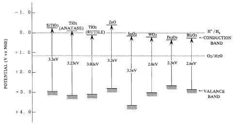
FIG. 1 shows the energy level of the valance band and the conduction band of
various semiconductor photocatalysts usable in the present invention;
FIGS. 2A and 2B are schematic cross-sectional views in a microscopically
enlarged scale of the photocatalytic coating formed on the surface of a
substrate and showing the hydroxyl groups being chemisorbed on the surface
upon photoexcitation of the photocatalyst;
FIGS. 3-5, 7 and 9 are graphs respectively showing the variation, in response
to time, of the contact angle with water of various specimens in the Examples
as the specimens are subjected to irradiation of ultraviolet light;
FIG. 6 shows Raman spectra of a surface of photocatalytic coating made of
silicone;
FIGS. 8 and 16 are graphs showing the result of pencil hardness tests;
CA 02215925 2006-09-26
14d
FIG. 10 is a graph showing the relationship between the thickness of the
photocatalytic coating and the capability of the coating to decompose methyl
mercaptan;
FIGS. 11A and 11B are front and side elevational views, respectively, of
outdoor accelerated fouling testing equipment;
FIGS. 12-15 are graphs showing the contact angle with water versus the
molar ratio of silica in silica-blended titania;
FIG. 17 is a graph showing to what degree various surfaces having different
hydrophilicity are fouled by city grime and sludge; and,
FIGS. 18 are graphs showing the variation, in response to time, of the contact
angle with water when ultraviolet light having different wavelengths is
irradiated on the surface of
CA 02215925 1997-09-19
PCT/JP96/00733
the photocatalytic coating.
Best Mode for Carrying Out the Invention
A substrate having a surface requiring superhydro-
5 philification is prepared and is coated with a photocatalytic
coating. In the case where the substrate is made from a heat
resistive material such as metal, ceramics and glass, the
photocatalytic coating may be fixed on the surface of the
substrate by sintering particles of a photocatalyst as
10 described later. Alternatively, a thin film of the amorphous
form of a precursor of the photocatalyst may be first formed on
the surface of the substrate and the amorphous photocatalyst
precursor may then be transformed into photoactive
photocatalyst by heating and crystallization.
15 In the case where the substrate.is formed of a non heat-
resistive material such as plastic or is coated with a paint,
the photocatalytic coating may be formed by applying onto the
surface a photooxidation-resistant coating composition
containing the photocatalyst and by curing the coating
composition, as described later.
When an antifogging mirror is to be manufactured, a
reflective coating may be first formed on the substrate and the
photocatalytic coating may then be formed on the front surface
of the mirror. Alternatively, the reflective coating may be
formed on the substrate prior to, subsequent to. or during the
course of the step of coating of the photocatalyst.
Photocatalyst
The most preferred example of the photocatalyst usable in
the photocatalytic coating according to the invention is
titania (Ti02). Titania is harmless, chemically stable and
available at a low cost. Furthermore, titania has a high band
gap energy and, hence, requires ultraviolet (W) light for
photoexcitation. This means that absorption of the visible
light does not occur during the course of photoexcitation so
CA 02215925 1997-09-19
PCT/JP96/00733
16
that the coating is free from the problem of coloring which
would otherwise occur due to a complementary color component.
Accordingly, titania is particularly suitable to coat on a
transparent member such as glass, lens and mirror.
As titania, both anatase and rutile may be used. The
advantage of the anatase form of titania is that a sol in which
extremely fine particles of anatase are dispersed is readily
available on the market so that it is easy to make an extremely
thin film. On the other hand, the advantage of the rutile form
of titania is that it can be sintered at a high temperature so
that a coating excellent in strength and abrasion resistivity
can be obtained. Although the rutile form of titania is lower
in the conduction band level than the anatase form as shown in
FIG. 1, it may be used as well for the purpose of
photocatalytic superhydrophilification.
It is believed that, when a substrate 10 is coated with a
photocatalytic coating 12 of titania and upon photoexcitation
of titania by UV light, water is chemisorbed on the surface in
the form of hydroxyl groups (OH-) under the photocatalytic
action as shown in FIG. 2A and, as a result, the surface
becomes superhydrophilic.
Other photocatalysts which can be used in the
photocatalytic coating according to the invention may include a
metal oxide such as ZnO, Sn02, SrTi03, W03, Bi203, and Fe203,
as shown in FIG. 1. It is believed that, similar to titania,
these metal oxides are apt to adsorb the surface hydroxyl
groups (OH-) because the metallic element and oxygen are
present at the surface.
As shown in FIG. 2B, the photocatalytic coating may be
formed by blending particles 14 of photocatalyst in a layer 16
of metal oxide. In particular, the surface can be
hydrophilified to a high degree when silica or tin oxide is
blended in the photocatalyst as described later.
Thickness of Photocatalytic Coating
CA 02215925 1997-09-19
PCT/JP96/00733
17
In the case that the substrate is made of a transparent
material as in the case of glass, a lens and a mirror, it is
preferable that the thickness of the photocatalytic coating is
not greater than 0.2 m. With such a thickness, coloring of the
photocatalytic coating due to the interference of light can be
avoided. Moreover, the thinner the photocatalytic coating is,
the more transparent the substrate can be. In addition, the
abrasion resistance of the photocatalytic coating is increased
with decreasing thickness.
The surface of the photocatalytic coating may be covered
further by an abrasion-resistant or corrosion-resistant
protective layer or other functional film which is susceptible
to hydrophilification.
Formation of Photocatalytic Layer by Calcination
of Amorphous Titania
In the case that the substrate is made of a heat resistive
material such as metal, ceramics and glass, one of the
preferred methods for forming an abrasion resistant
photocatalytic coating which exhibits the superhydrophilicity
of such a degree that the contact angle with water becomes as
small as 0 is to first form a coating of the amorphous form of
titania on the surface of the substrate and to then calcine the
substrate to thereby transform by phase transition amorphous
titania into crystalline titania (i.e., anatase or rutile).
Formation of amorphous titania may be carried out by one of the
following methods.
(1) Hydrolysis and Dehydration Polymerization of Organic
Titanium Compound
Alkoxide of titanium, such as tetraethoxytitanium,
tetraisopropoxytitanium,tetra-n-propoxytitanium,
tetrabuthoxytitanium, and tetramethoxytitanium,is used to
which is added a hydrolysis inhibitor such as hydrochloric acid
and ethylamine, the mixture being diluted by alcohol such as
ethanol and propanol. While subjected to partial or complete
CA 02215925 1997-09-19
PCT/JP96/00733
18
hydrolysis, the mixture is applied on the surface of the
substrate by spray coating, flow coating, spin coating, dip
coating, roll coating or any other suitable coating method,
followed by drying at a temperature ranging from the ambient
temperature to 200 C. Upon drying, hydrolysis of titanium
alkoxide will be completed to result in the formation of
titanium hydroxide which then undergoes dehydration
polymerization whereby a layer of amorphous titania is formed
on the surface of the substrate.
In lieu of titanium alkoxide, other organic compounds of
titanium such as chelate of titanium and acetate of titanium
may be employed.
(2) Formation of Amorphous Titania from Inorganic
Titanium Compound
Acidic aqueous solution of inorganic compound of titanium
such as TiCl4 and Ti(S04)2 is applied on the surface of the
substrate by spray coating, flow coating, spin coating, dip
coating, or roll coating. The substrate is then dried at a
temperature of 100-200 C to subject the inorganic compound of
titanium to hydrolysis and dehydration polymerization to form a
layer of amorphous titania on the surface of the substrate.
Alternatively, amorphous titania may be formed on the surface
of the substrate by chemical vapor deposition of TiC14.
(3) Formation of Amorphous Titania by Sputtering
Amorphous titania may be deposited on the surface of the
substrate by electron beam bombardment of a target of metallic
titanium in an oxidizing atmosphere.
(4) Calcination Temperature
Calcination of amorphous titania may be carried out at a
temperature at least higher than the crystallization
temperature of anatase. Upon calcination at a temperature of
400-500 C or more, amorphous titania may be transformed into
the anatase form of titania. Upon calcination at a temperature
of 600-700 C or more, amorphous titania may be transformed
into the rutile form of titania.
CA 02215925 1997-09-19
PCT/JP96/00733
19
(5) Formation of Diffusion Prevention Layer
In the case that the substrate is made of glass or glazed
tile which contains alkaline network-modifier ions such as
sodium, it is preferable that an intermediate layer of silica
and the like is formed between the substrate and the layer of
amorphous titania prior to calcination. This arrangement
prevents alkaline network-modifier ions from being diffused
from the substrate into the photocatalytic coating during
calcination of amorphous titania. As a result,
superhydrophilification is accomplished to the degree that the
.
contact angle with water becomes as small as 00
Photocatalytic Layer of Silica-Blended Titania
Another preferred method of forming an abrasion resistant
photocatalytic coating which exhibits the superhydrophilicity
of such a degree that the contact angle with water is equal to
0 is to form on the surface of the substrate a photocatalytic
coating comprised of a mixture of titania and silica. The rate
of silica to the sum of titania and silica may be 5-90 % by
mol, preferably 10-70 % by mol, more preferably 10-50 % by mol.
Formation of photocatalytic coating comprised of silica-blended
titania may be carried out by one of the following methods.
(1) A suspension containing particles of the anatase form
or rutile form of titania and particles of silica is applied on
the surface of the substrate, followed by sinte-ring at a
temperature less than the softening point of the substrate.
(2) A mixture of a precursor of amorphous silica (e.g.,
tetraalkoxysilane such as tetraethoxysilane,
tetraisopropoxysilane,tetra-n-propoxysilane,
tetrabuthoxysilane,and tetramethoxysilane; silanol formed by
hydrolysis of tetraalkoxysilane; or polysiloxane having a mean
molecular weight of less than 3000) and a crystalline titania
sol is applied on the surface of the substrate and is subjected
to hydrolysis where desired to form silanol, followed by
heating at a temperature higher than about 100 C to subject
CA 02215925 1997-09-19
PCT/JP96/00733
silanol to dehydration polymerization to thereby form a
photocatalytic coating wherein titania particles are bound by
amorphous silica. In this regard, if dehydration polymerization
of silanol is carried out at a temperature higher than about
5 200 C, polymerization of silanol is accomplished to a high
degree so that the alkali resistance of the photocatalytic
coating is enhanced.
(3) A suspension wherein particles of silica are dispersed
in a solution of a precursor of amorphous titania (e.g.,
10 organic compound of titanium such as alkoxide, chelate or
acetate of titanium; or inorganic compound of titanium such as
TiC14 and Ti(SO4)2) is applied on the surface of the substrate
and then the compound of titanium is subjected to hydrolysis
and dehydration polymerization at a temperature ranging from
15 the ambient temperature to 200 C to thereby form a thin film of
amorphous titania wherein particles of silica are dispersed.
Then, the thin film is heated at a temperature higher than the
crystallization temperature of titania but lower than the
softening point of the substrate to thereby transform amorphous
20 titania into crystalline titania by phase transition.
(4) Added to a solution of a precursor of amorphous
titania (organic compound of titanium such as alkoxide, chelate
or acetate of titanium; or inorganic compound of titanium such
as TiC14 and Ti(S04)2) is a precursor of amorphous silica
(e.g., tetraalkoxysilane such as tetraethoxysilane,
tetrai sopropoxysi lane, tetra-n-propoxysi lane,
tetrabuthoxysi lane, and tetramethoxysilane; hydrolyzate
thereof, i.e., silanol; or polysiloxane having a mean molecular
weight of less than 3000) and the mixture is applied on the
surface of the substrate. Then, these precursors are subjected
to hydrolysis and dehydration polymerization to form a thin
film made of a mixture of amorphous titania and amorphous
silica. Thereafter, the thin film is heated at a temperature
higher than the crystallization temperature of titania but
lower than the softening point of the substrate to thereby
CA 02215925 1997-09-19
PCT/JP96/00733
21
transform amorphous titania into crystalline titania by phase
transition.
Photocatalytic Layer of Tin Oxide-Blended Titania
Still another preferred method of forming an abrasion
resistant photocatalytic coating which exhibits the
superhydrophilicity of such a degree that the contact angle
with water is equal to 0 is to form on the surface of the
substrate a photocatalytic coating comprised of a mixture of
titania and tin oxide. The rate of tin oxide to the sum of
titania and tin oxide may be 1-95 % by weight, preferably 1-50
% by weight. Formation of a photocatalytic coating comprised of
tin oxide-blended titania may be carried out by one of the
following methods.
(1) A suspension containing particles of the anatase form
or rutile form of titania and particles of tin oxide is applied
on the surface of the substrate, followed by sintering at a
temperature less than the softening point of the substrate.
(2) A suspension wherein particles of tin oxide are
dispersed in a solution of a precursor of amorphous titania
(e.g., organic compound of titanium such as alkoxide, chelate
or acetate of titanium; or inorganic compound of titanium such
as TiC14 and Ti(S04)2) is applied on the surface of the
substrate and then the compound of titanium is subjected to
hydrolysis and dehydration polymerization at a temperature
ranging from the ambient temperature to 200 C to thereby form a
thin film of amorphous titania wherein particles of tin oxide
are dispersed. Then, the thin film is heated at a temperature
higher than the crystallization temperature of titania but
lower than the softening point of the substrate to thereby
transform amorphous titania into crystalline titania by phase
transition.
Silicone Paint Containing Photocatalyst
A further preferred method of forming a photocatalytic
CA 02215925 1997-09-19
PCT/JP96/00733
22
coating which exhibits the superhydrophilicity of such a
degree that the contact angle with water is equal to 0 is to
use a coating composition wherein particles of a photocatalyst
are dispersed in a film forming element of uncured or partially
cured silicone (organopolysiloxane) or a precursor thereof.
The coating composition is applied on the surface of the
substrate and the film forming element is then subjected to
curing. Upon photoexcitation of the photocatalyst, the organic
groups bonded to the silicon atoms of the silicone molecules
are substituted with hydroxyl groups under the photocatalytic
action of the photocatalyst, as described later with reference
to Examples 13 and 14, whereby the surface of the
photocatalytic coating is superhydrophilified.
This method provides several advantages. Since the
photocatalyst-containing silicone paint can be cured at ambient
temperature or at a relatively low temperature, this method may
be applied to a substrate formed of a non-heat-resistant
material such as plastics. The coating composition containing
the photocatalyst may be applied whenever desired by way of
brush painting, spray coating, roll coating and the like on any
existing substrate requiring superhydrophilification of the
surface. Superhydrophilification by photoexcitation of the
photocatalyst may be readily carried out even by the sunlight
as a light source.
Furthermore, in the event that the coating_film is formed
on a plastically deformable substrate such as a steel sheet, it
is possible to readily subject the steel sheet to plastic
working as desired after curing of the coating film and prior
to photoexcitation. Prior to photoexcitation, the organic
groups are bonded to the silicon atoms of the silicone
molecules so that the coating film has an adequate flexibility.
Accordingly, the steel sheet may be readily deformed without
damaging the coating film. After plastic deformation, the
photocatalyst may be subjected to photoexcitation whereupon the
organic groups bonded to the silicon atoms of the silicone
CA 02215925 1997-09-19
PCT/JP96/00733
23
molecules will be substituted with hydroxyl groups under the
action of photocatalyst to thereby render the surface of the
coating film superhydrophilic.
The photocatalyst-containing silicone paint has a
sufficient resistance against photooxidation action of the
photocatalyst since it is composed of the siloxane bond.
Another advantage of the photocatalytic coating made of
photocatalyst-containing silicone paint is that, once the
surface has been rendered superhydrophilic, the
superhydrophilicity is maintained for a long period of time
even if the coating is kept in the dark and that the
superhydrophilicity can be restored even by the light of an
indoor illumination lamp such as fluorescent lamp.
Examples of the film forming element usable in the
invention include methyltrichlorosil.ane,methyltribromosilane,
methyltrimethoxysilane,methyltriethoxysilane,
methyltriisopropoxysilane,methyltri-t-buthoxysilane;
ethyl trichl oro silane, ethyltribromo s i lane,
ethyltrimethoxysilane,ethyltriethoxysilane,
ethyltriisopropoxysilane,ethyltri-t-buthoxysilane;
n-propyltrichlorosilane,n-propyltribromosilane,
n-propyltrimethoxysilane,n-propyltriethoxysilane,
n-propyltriisopropoxysilane,n-propyltri-t-buthoxysilane;
n-hexyltrichlorosilane,n-hexyltribromosilane,
n-hexyltrimethoxysilane,n-hexyltriethoxysilane,
n-hexyltriisopropoxysilane,n-hexyltri-t-buthoxysilane;
n-decyltrichlorosilane,n-decyltribromosilane,
n-decyltrimethoxysilane,n-decyltriethoxysilane,
n-decyltriisopropoxysilane,n-decyltri-t-buthoxysilane;
n-octadecyltrichlorosilane,n-octadecyltribromosilane,
n-octadecyltrimethoxysilane,n-octadecyltriethoxysilane,
n-octadecyltriisopropoxysilane,n-octadecyltri-t-buthoxysilane;
phenyltrichl orosi lane, phenyl tribromos i lane,
phenyltrimethoxysilane,phenyltriethoxysilane,
phenyltriisopropoxysilane, phenyltri -t-buthoxysi lane;
CA 02215925 1997-09-19
PCT/JP96/00733
24
tetrachlorosi lane, tetrabromosi lane, tetramethoxysilane,
tetraethoxysi lane, tetrabuthoxysi lane, dimethoxydiethoxysi lane;
dimethyldichlorosilane,dimethyldibromosilane,
dimethyldimethoxysilane,dimethyldiethoxysilane;
diphenyldichlorosilane,diphenyldibromosilane,
diphenyldimethoxysilane,diphenyldiethoxysilane;
phenylmethyldichlorosilane,phenylmethyldibromosilane,
phenylmethyldimethoxysilane,phenylmethyldiethoxysilane;
tri chlorohydrosi lane, tribromohydrosi lane,
trimethoxyhydros i lane, tri ethoxyhydrosi lane,
triisopropoxyhydrosilane,tri-t-buthoxyhydrosilane;
vinyl trichloro s i lane, vinyltribromosilane,
vinyl trimethoxys i lane, vinyl tri ethoxysi lane,
vinyltriisopropoxysilane,vinyltri-t-buthoxysilane;
trifluoropropyltrichlorosilane,trifluoropropyltribromosilane,
trifluoropropyltrimethoxysilane,trifluoropropyltriethoxy-
silane, trifluoropropyltriisopropoxysilane,trifluoropropyltri
t-buthoxysilane; gamma -glycidoxypropylmethyldimethoxys i lane,
gamma-glycidoxypropylmethyldiethoxysilane, gamma-glycidoxy-
propyltrimethoxysilane,gamma-glycidoxypropyltriethoxysilane,
gamma-glycidoxypropyltriisopropoxysilane, gamma-glycidoxy-
propyltri-t-buthoxysilane;gamma-methacryloxypropylmethyl-
dimethoxysilane, gamma -methacryl oxypropylmethyldi ethoxys i lane,
gamma-methacryloxypropyltrimethoxysilane, gamma-methacryloxy-
propyltri ethoxys i lane, gamma -methacryl oxypropyl trii sopropoxy
silane, gamma-methacryloxypropyltri-t-buthoxysilane;gamma-
aminopropylmethyldimethoxysilane,gamma-aminopropylmethyl-
diethoxysilane, gamma-aminopropyltrimethoxysilane,gamma-
aminopropyltriethoxysilane,gamma-aminopropyltriisopropoxy
silane, gamma-aminopropyltri-t-buthoxysilane; gamma-
mercaptopropylmethyldimethoxysilane, gamma-mercaptopropyl-
methyldiethoxysilane,gamma-mercaptopropyltrimethoxysilane,
gamma-mercaptopropyltriethoxysilane, gamma-mercaptopropyl-
triisopropoxysilane,gamma-mercaptopropyltri-t-buthoxysilane;
t3-(3,4-epoxycyclohexyl)ethyltrimethoxysilane, !3-(3,4-
CA 02215925 1997-09-19
PCT/JP96/00733
epoxycyclohexyl)ethyltriethoxysilane; partial hydrolizate
thereof; and mixtures thereof.
To ensure that the silicone coating exhibits a
satisfactory hardness and smoothness, it is preferable that the
5 coating contains more than 10% by mol of a three-dimensionally
cross-linking siloxane. In addition, to provide an adequate
flexibility of the coating film yet assuring a satisfactory
hardness and smoothness, it is preferred that the coating
contains less than 60% by mol of a two-dimensionally cross-
10 linking siloxane. Furthermore, to enhance the speed that the
organic groups bonded to the silicon atoms of the silicone
molecules are substituted with hydroxyl groups upon
photoexcitation, it is desirable to use a silicone wherein the
organic groups bonded to the silicon atoms of the silicone
15 molecules are n-propyl or phenyl groups. In place of silicone
having the siloxane bond, organopolysilazane composed of a
silazane bond may be used.
Addition of Antibacterial Enhancer
20 The photocatalytic coating may be doped with a metal such
as Ag, Cu and Zn.
Doping of the photocatalyst with Ag, Cu or Zn may be
carried out by adding a soluble salt of such metal to a
suspension containing particles of the photocatalyst, the
25 resultant solution being used to form the photocatalytic
coating. Alternatively, after forming the photocatalytic
coating, a soluble salt of such metal may be applied thereon
and may be subjected to irradiation of light to deposit metal
by photoreduction.
The photocatalytic coating doped with Ag, Cu or Zn is
capable of killing bacteria adhered to the surface. Moreover,
such photocatalytic coating inhibits growth of microorganisms
such as mold, alga and moss. As a result, the surface of a
building, machine, apparatus, household, article and the like
can be maintained clean for a long period.
CA 02215925 1997-09-19
PCT/JP96/00733
26
Addition of Photoactivity Enhancer
The photocatalytic coating may additionally be doped with
a metal of the platinum group such as Pt, Pd, Rh, Ru, Os and
Ir. These metals may be similarly doped to the photocatalyst by
photoreduction deposition or by addition of a soluble salt.
A photocatalyst doped with a metal of the platinum group
develops an enhanced photocatalytic redox activity so that
decomposition of contaminants adhering on the surface will be
promoted.
Photoexcitation and UV Irradiation
For the antifogging purpose of a transparent member such
as glass, a lens and a mirror, it is preferable that the
photocatalytic coating is formed of such a photocatalyst like
titania that has a high band gap energy and can be photoexcited
only by W light. In that case, the photocatalytic coating does
not absorb the visible light so that glass, a lens or a mirror
would not be colored by a complementary color component. The
anatase form of titania may be photoexcited by a UV light
having a wavelength less than 387 nm, with the rutile form of
titania by a UV light having a wavelength less than 413 nm,
with tin oxide by a UV light having a wavelength less than 344
nm, with zinc oxide by a UV light having a wavelength less than
387 nm.
As a source of UV light, a fluorescent lamp, incandescent
lamp, metal halide lamp, mercury lamp or other type of indoor
illumination lamp may be used. As the antifogging glass, lens
or mirror is exposed to UV light, the surface thereof will be
superhydrophilified by photoexcitation of the photocatalyst.
In a situation where the photocatalytic coating is exposed to
the sunlight as in the case of a rearview mirror of a vehicle,
the photocatalyst will advantageously be photoexcited
spontaneously by the UV light contained in the sunlight.
Photoexcitation may be carried out, or caused to be
CA 02215925 1997-09-19
PCT/JP96/00733
27
carried out, until the contact angle, with water, of the
surface becomes less than about 10 , preferably less than about
, particularly equal to about 0 . Generally, by photoexciting
at a UV intensity of 0.001 mW/cm2, the photocatalytic coating
5 will be superhydrophilified within several days to the degree
that the contact angle with water becomes about 0 . Since the
intensity of the UV light contained in the sunlight impinging
upon the earth's surface is about 0.1-1 mW/cm2, the surface
will be superhydrophilified in a shorter time when exposed to
the sunlight.
In the case that the surface of the substrate is to be
self-cleaned by rainfall or to be prevented from adhesion of
contaminants, the photocatalytic coating may be formed of a
photocatalyst which can be photoexcited by UV light or visible
light. The articles covered by the photocatalytic coating are
disposed outdoors and are subjected to irradiation of the
sunlight and to rainfall.
When the photocatalytic coating is made of titania-
containing silicone, it is preferable to photoexcite the
photocatalyst at such an intensity to ensure that a sufficient
amount of the surface organic groups bonded to the silicon
atoms of the silicone molecules are substituted with hydroxyl
groups. The most convenient method therefor is to use the
sunlight.
Once the surface has been made highly hydrophilic, the
hydrophilicity is sustained even during the night. Upon
exposure again to the sunlight, the hydrophilicity will be
restored and maintained.
It is preferable that the photocatalytic coating is
superhydrophilified in advance before the substrate coated by
the photocatalytic coating according to the invention is
offered for use to the user.
Examples
The following Examples illustrate the industrial
CA 02215925 1997-09-19
PCT/JP96/00733
28
applicability of the invention from various aspects.
Example 1
Antifogging Mirror - Antifogging Photocatalytic Coating
with Interleaved Silica Layer
6 parts by weight of tetraethoxysilane Si(OC2H5)4 (Wako
JunYaku, Osaka), 6 parts by weight of pure water, and 2 parts
by weight of 36% hydrochloric acid as a hydrolysis inhibitor
were added to 86 parts by weight of ethanol as a solvent and
the mixture was stirred to obtain a silica coating solution.
The solution was allowed to cool for about 1 hour since the
solution evolved heat upon mixing. The solution was then
applied on the surface of a soda-lime glass plate of 10cm
square in size by the flow coating method and was dried at a
temperature of 80 C. As drying proceeds, tetraethoxysilane was
hydrolyzed to first form silanol Si(OH)4 which was then
underwent dehydration polymerization to form a thin film of
amorphous silica on the surface of the glass plate.
Then a titania coating solution was prepared by adding 0.1
parts by weight of 36% hydrochloric acid as a hydrolysis
inhibitor to a mixture of 1 part by weight of tetraethoxy-
titanium Ti(OC2H5)4 (Merck) and 9 parts by weight of ethanol,
and the solution was applied to the surface of the above-
mentioned glass plate by the flow coating method in dry air.
The amount of coating was 45 g/cm2 in terms of_titania. As the
speed of hydrolysis of tetraethoxytitanium was so high,
hydrolysis of tetraethoxytitanium partially commenced during
the course of coating so that formation of titanium hydroxide
Ti(OH)4 started.
Then the glass plate was held at a temperature of about
150 C for 1-10 minutes to permit completion of the hydrolysis
of tetraethoxy-titanium and to subject the resultant titanium
hydroxide to dehydration polymerization whereby amorphous
titania was formed. In this manner, a glass plate was obtained
having a coating of amorphous titania overlying the coating of
CA 02215925 1997-09-19
PCT/JP96/00733
29
amorphous silica.
This specimen was then fired or calcined at a temperature
of 500 C in order to transform amorphous titania into the
anatase form of titania. It is considered that, due to the
presence of the coating of amorphous silica underlying the
coating of amorphous titania, alkaline network-modifier ions
such as sodium ions being present in the glass plate were
prevented from diffusing from the glass substrate into the
titania coating during calcination.
Then a reflective coating of aluminum was formed by vacuum
evaporation deposition on the back of the glass plate to
prepare a mirror to thereby obtain #1 specimen.
After the #1 specimen was kept in the dark for several
days, a UV light was irradiated on the surface of the specimen
for about one hour at the UV intensity of 0.5 mW/cm2 (the
intensity of UV light having an energy higher than the band gap
energy of the anatase form of titania, i. e., the intensity of
UV light having a wavelength shorter than 387 nm) by using a
20W blue-light-black (BLB) fluorescent lamp (Sankyo Electric,
FL20BLB) to obtain #2 specimen.
For the purposes of comparison, a reflective coating of
aluminum was formed by vacuum evaporation deposition on the
back of a glass plate provided neither with silica nor titania
coating, the product being placed in the dark for several days
to obtain #3 specimen.
The contact angle, with water, of the #2 and #3 specimens
was measured by a contact angle meter (Kyowa Kaimen Kagaku K.K.
of Asaka, Saitama, Model CA-X150). The resolving power at the
small angle side of this contact angle meter was V. The
contact angle was measured 30 seconds after a water droplet was
dripped from a micro-syringe onto the surface of the respective
specimens. In the #2 specimen, the reading of the contact angle
meter, indicating the contact angle with water of the surface,
was 0 so that the surface exhibited superhydrophilicity.In
contrast, the contact angle with water of the #3 specimen was
CA 02215925 1997-09-19
PCT/JP96/00733
30-40 .
Then the #2 and #3 specimens were tested for the
antifogging capability as well as to see how adherent
waterdroplets would spread over the surface. Assessment of the
5 antifogging capability was done by filling a 500 ml beaker with
300 ml of hot water of about 80 C, by thereafter placing on the
beaker each specimen for about 10 seconds with the front
surface of the mirror directed downwards, and by inspecting
immediately thereafter the presence or absence of a fog on the
10 surface of the specimen and inspecting how the face of the
tester reflected.
With the #3 specimen, the surface of the mirror was fogged
by steam so that the image of the observer's face was not
reflected well. However, with the #2 specimen, no fogging was
15 observed at all and the face of the tester was clearly
reflected.
Assessment of the manner of adherent water droplets to
spread was carried out by dripping several water droplets from
a pipette onto the surface of the mirror inclined at an angle
20 of 45 , rotating the mirror into a vertical position, and
thereafter inspecting how the droplets adhered and how the face
of the observer reflected.
With the #3 specimen, dispersed discrete waterdroplets
which were obstructive to the eye adhered on the mirror
25 surface. As a result, the reflected image was disturbed by the
refraction of light due to adherent droplets so that it was
difficult to observe the reflected image with clarity. In
contrast, with the #2 specimen, water droplets adhered onto the
mirror surface were allowed to spread over the surface to form
30 a uniform water film without forming discrete waterdroplets.
Although a slight distortion of the reflected image due to the
presence of the water film was observed, it was possible to
recognize the reflected image of the tester's face with a
sufficient clarity.
CA 02215925 1997-09-19
PCT/JP96/00733
31
Example 2
Antifogging Mirror - Photocatalytic Coating Comprising
Silica-Blended Titania
A thin film of amorphous silica was formed on the surface
of a mirror (made by Nihon Flat Glass, MFL3) in a manner
similar to Example 1.
Then a coating solution was prepared by admixing 0.69g of
tetraethoxysilane (Wako JunYaku), 1.07g of a sol of the anatase
form of titania (Nissan Chemical Ind., TA-15, mean particle
size of 0.01 N.m), 29.88g of ethanol, and 0.36g of pure water.
The coating solution was applied on the surface of the mirror
by spray coating process. The mirror was held at a temperature
of about 150 C for about 20 minutes to subject
tetraethoxysilane to hydrolysis and dehydration polymerization
to thereby form on the mirror surface a coating wherein
particles of the anatase form of titania were bound by a binder
of amorphous silica. The ratio by weight of titania to silica
was 1.
After the mirror was kept in the dark for several days, a
W light was irradiated by the BLB fluorescent lamp for about
one hour at the W intensity of 0.5 mW/cm2 to obtain #1
specimen. As the contact angle with water of the surface of the
mirror was measured by the same contact angle meter as used in
Example 1, the reading of the contact angle meter was 0 .
Then, in the manner similar to Example 1, the antifogging
capability and the manner of adherent water droplets to spread
were assessed with respect to the #1 specimen as well as to the
"MFL3" mirror not provided with the photocatalytic coating. In
the test for antifogging property, with the #1 specimen, no fog
was observed at all and the tester's face was clearly
reflected, in contrast to the "MFL3" mirror wherein a fog was
observed on the surface of the mirror so that the image of the
tester's face was not clearly reflected. In the inspection for
the manner of adherent water droplets to spread, with the
"MFL3" mirror, water droplets dispersed on the surface caused
CA 02215925 1997-09-19
PCT/JP96/00733
32
refraction of light to thereby disturb the reflected image, so
that it was difficult to clearly observe the reflected image.
With the #1 specimen, in contrast, water droplets adhered to
the surface of the mirror were spread over the surface to form
a uniform water film and, although a slight distortion was
observed in the reflected image due to the presence of the
water film, it was possible to recognize the reflected image of
the tester's face with a sufficient clarity.
Example 3
Antifogging Eyeglass Lens
First, a thin film of amorphous silica was formed in a
manner similar to Example 1 on both sides of an eyeglass lens
commercially available on the market.
Then, the coating solution similar to that of Example 2
was spray coated on both sides of the lens and the lens was
held at a temperature of about 150 C for about 20 minutes to
subject tetraethoxysilane to hydrolysis and dehydration
polymerization to thereby form on each side of the lens a
coating wherein particles of the anatase form of titania were
bound by a binder of amorphous silica.
After the lens was kept in the dark for several days, a UV
light was irradiated by the BLB fluorescent lamp for about one
hour at the UV intensity of 0.5 mW/cm2. When the contact angle
with water of the surface of the lens was measu-red by the same
contact angle meter as used in Example 1, the reading of the
contact angle meter was 0 . This lens was mounted to the right-
hand frame of eyeglasses, with an ordinary lens being mounted
for the purposes of comparison to the left-hand frame.
When, several hours later, the tester wore the glasses and
took a bath for about 5 minutes, the ordinary lens on the left
was fogged with steam so that the eyesight was lost. However,
formation of fog was not observed at all on the right-hand lens
coated with the photocatalytic coating that had been subjected
to UV irradiation.
CA 02215925 1997-09-19
PCT/JP96/00733
33
As the tester then intentionally directed a shower on the
glasses, obstructive waterdroplets adhered on the left-hand
ordinary lens so that a view was interrupted. However,
waterdroplets adhering on the right-hand lens promptly spread
into water film so that a sufficient view was secured.
Example 4
Antifogging Glass - 7 nm Thick Titania Coating
A solution containing chelate of titanium was applied on
the surface of a soda-lime glass plate of 10cro square in size
and titanium chelate was subjected to hydrolysis and
dehydration polymerization to form amorphous titania on the
surface of the glass plate. The plate was then calcined at a
temperature of 500 C to form a surface layer of crystals of the
anatase form of titania. The thickness of the surface layer was
7 nm.
The surface of the thus obtained specimen was first
subjected to irradiation by a W light for about one hour at
the UV intensity of 0.5 mW/cm2 by using a BLB fluorescent lamp.
As the contact angle with water of the surface of this specimen
was measured by a contact angle meter (made by ERMA, Model G-I-
1000, the resolving power at the small angle side being 3 ),
the reading of the contact angle meter was less than 3 .
Then, while irradiating by a UV light at the UV intensity
of 0.01 mW/cm2 by using a 20W white fluorescent lamp (Toshiba,
FL20SW), the variation, in response to time, of the contact
angle was measured. The results are plotted in the graph of
FIG. 3. It will be noted from the graph that the surface of the
specimen was maintained highly hydrophilic even by a weak UV
light emitted from the white fluorescent lamp.
This Example illustrates that the surface of the
photocatalytic titania coating can be maintained highly
hydrophilic even though the thickness thereof is made as
extremely small as 7 nm. This is very important in preserving
the transparency of a substrate such as a windowpane.
CA 02215925 1997-09-19
PCT/JP96/00733
34
Example 5
Antifogging Glass - 20 nm Thick Titania Coating
A surface layer of anatase-form titania crystals was
formed on the surface of a soda-lime glass plate in a manner
similar to Example 4. The thickness of the surface layer was 20
nm.
Similar to Example 4, the surface of the thus obtained
specimen was first subjected to irradiation by a UV light for
about one hour at the UV intensity of 0.5 mW/cm2 by using a BLB
fluorescent lamp, and then the variation in response to time of
the contact angle was measured while subjecting to irradiation
by a UV light at the UV intensity of 0.01 mW/cm2 by using a
white fluorescent lamp. The results are shown in the graph of
FIG. 4. In this Example, too, the surface of the specimen was
maintained highly hydrophilic by a weak UV light emitted from a
white fluorescent lamp.
Example 6
Antifogging Glass - Effect of Calcination Temperature
of Amorphous Titania
In a manner similar to Example 1, a thin film of amorphous
silica was first formed on the surface of soda-lime glass
plates of 10cro square in size and then a thin film of amorphous
titania was coated thereon to obtain a plurality of specimens.
These glass plates were then calcined at a temperature of
450 C, 475 C, 500 C, and 525 C, respectively. Upon inspection
by the powder X-ray diffraction method, the presence of
crystalline titania of the anatase form was detected in the
specimens calcined at 475 C, 500 C, and 525 C so that
transformation of amorphous titania into the anatase form
crystalline titania was confirmed in these specimens. However,
in the specimen calcined at 450 C, the anatase form of titania
was not detected.
The surface of the thus obtained specimens was first
CA 02215925 1997-09-19
PCT/JP96/00733
subjected to irradiation by a UV light for about three hours at
the UV intensity of 0.5 mW/cm2 by using a BLB fluorescent lamp,
and then the variation in response to time of the contact angle
was measured by the contact angle meter (CA-X150) while
5 subjected to irradiation by a UV light at the UV intensity of
0.02 mW/cm2 by using a white fluorescent lamp. The results are
shown in Table 1.
Table 1
Contact Angle ( )
a cs.na s.on imme . att ays ays 14 ays
Temp ( C) BLB irradn later later later
450 10 13 15 23
475 0 0 0 0
500 0 0 0 0
525 0 0 0 0
As will be apparent from Table 1, it was found that, in
the specimens which were calcined at a temperature of 475 C,
500 C, and 525 C and in which the formation of anatase crystals
were confirmed, the contact angle was maintained at 0 and the
surface of the glass plate maintained superhydrophilic as long
as irradiation of the UV light by a white fluorescent lamp was
continued. In contrast, it was observed that the coating of
amorphous titania of the specimen calcined at 450 C did not
exhibit photocatalytic activity so that the contact angle
increased as time elapsed.
When a blow of breath was blown upon the specimens
calcined at a temperature of 475 C, 500 C, and 525 C, no
formation of fog was observed on the specimen surface.
Example 7
Antifogging Glass - Effect of
Alkaline Network Modifier Ion Diffusion
A titania coating solution similar to Example 1 was
prepared and was applied by the flow coating method on the
CA 02215925 1997-09-19
PCT/JP96/00733
36
surface of a 10cro square soda-lime glass plate. Similar to
Example 1, the amount of coating was 45 g/cm2 in terms of
titania.
The glass plate was similarly held at a temperature of
about 150 C for 1-10 minutes to form amorphous titania on the
surface of the glass plate. The specimen was then calcined at a
temperature of 500 C to transform amorphous titania into the
anatase form of titania.
After keeping the specimen in the dark for several days, a
UV light was irradiated on the surface of the specimen for
about one hour at the UV intensity of 0.5 mW/cm2 by using a BLB
fluorescent lamp. Thereafter, the contact angle with water was
measured by the contact angle meter (CA-X150), which indicated
a contact angle of 3 .
It is considered that the reason why in this specimen the
contact angle was not reduced down to 0 is that because,
contrary to Example 1, the specimen of this Example was not
provided with a silica layer interleaved between the glass
substrate and the titania layer, the alkaline network-modifier
ions such as sodium ions were allowed to diffuse from the glass
substrate into the titania coating during calcination at 500 C
whereby the photocatalytic activity of titania was hindered.
It is therefore believed that, in order to realize the
superhydrophilicity of such a degree that the contact angle
with water is equal to 0 , it is preferable to provide an
intermediate layer of silica as in Example 1.
Example 8
Antifogging Glass - Formation of Amorphous Titania By
Sputtering
A film of metallic titanium was deposited by sputtering on
the surface of a 10cro square soda-lime glass plate which was
then calcined at a temperature of 500 C. Upon inspection by the
powder X-ray diffraction method, formation of the anatase form
of titania was observed on the surface of the glass plate.
CA 02215925 1997-09-19
PCT/JP96/00733
37
Obviously, metallic titanium was oxidized into anatase by
calcination.
Soon after calcination, the surface of the specimen was
subjected to irradiation by a UV light at the UV intensity of
0.5 mW/cm2 by using a BLB fluorescent lamp and the contact
angle with water was measured by the contact angle meter (CA-
X150) to monitor the variation in response to time of the
contact angle. The results are shown in the graph of FIG. 5. As
will be apparent from the graph, the contact angle with water
was kept less than 3 . This experiment illustrates that, even
in the case where the photocatalytic coating is formed by
sputtering, the surface of a glass plate is maintained highly
hydrophilic upon UV irradiation.
Example 9
Antifogging Glass - UV Intensity of 800 Lux
A thin film of amorphous silica was formed on the surface
of a 10cro square soda-lime glass plate in a manner similar to
Example 1.
Then the coating solution of Example 2 was applied by
spray coating on the surface of the glass plate. The glass
plate was then held at a temperature of about 150 C for about
20 minutes whereby a coating in which particles of the anatase
form of titania were bound by a binder of amorphous silica was
formed on the surface of the glass plate. The ratio by weight
of titania to silica was 1.
After kept in the dark for several days, the glass plate
was subjected to irradiation by a UV light for about one hour
at the UV intensity of 0.5 mW/cm2 by a BLB fluorescent lamp.
After UV irradiation, the contact angle with water of the
surface of the glass plate was measured by the contact angle
meter (CA-X150) and it was found that the contact angle was 0 .
Thereafter, the specimen was subjected to irradiation by a
UV light for 4 days at the UV intensity of 0.004 mW/cm2 (800
lux) by using a white fluorescent lamp. While the specimen was
CA 02215925 1997-09-19
PCT/JP96/00733
38
under UV irradiation, the contact angle at the surface thereof
was maintained less than 2 . When 4 days later a blow of breath
was blown upon the specimen, formation of fog was not observed.
In this way, it was confirmed that, by a weak UV light
available under indoor illumination achieved for example by a
white fluorescent lamp, the surface of the glass plate was
maintained highly hydrophilic and fogging of the glass plate
was prevented.
Example 10
Antifogging Glass - Effect of Silica-to-Titania Blending Ratio
Next, tetraethoxysi lane (Wako JunYaku), a sol of the
anatase form of titania (Nissan Chemical Ind., TA-15), ethanol,
and pure water were admixed in varying rate to prepare four
kinds of coating solutions having different tetraethoxysilane-
to-titania sol blending ratio. The rate of tetraethoxysilane to
titania sol was so selected that, after tetraethoxysilane was
converted into amorphous silica, the rate of silica with
respect to the sum of silica plus titania was equal to 10% by
mol, 30% by mol, 50% by mol, and 70% by mol, respectively.
Each of the coating solutions was applied by spray coating
on the surface of a 10cro square soda-lime glass plate which was
then held at a temperature of about 150 C for about 20 minutes
to subject tetraethoxysilane to hydrolysis and dehydration
polymerization whereby a coating in which particles of the
anatase form of titania were bound by a binder of amorphous
silica was formed on the surface of the glass plate.
After being kept in the dark for a week, the specimens
were subjected to irradiation by a UV light for about one hour
at the UV intensity of 0.3 mW/cm2 by a BLB fluorescent lamp.
After UV irradiation, the contact angle with water of the
surface of the respective specimens was measured by the contact
angle meter (CA-X150). The contact angle was 0 throughout all
the specimens.
Thereafter, two specimens with coatings having 30% by mol
CA 02215925 1997-09-19
PCT/JP96/00733
39
and 50% by mol of silica, respectively, were subjected to
irradiation by a UV light for 3 days at the Uv intensity of
0.004 mW/cm2 by using a white fluorescent lamp. While the
specimens were under irradiation, the contact angle at the
surface thereof was maintained less than 3 .
Example 11
Antifogging Glass - Rutile Form Photocatalytic Coating
A titania coating solution was prepared by adding 0.1 part
by weight of 36% hydrochloric acid as a hydrolysis inhibitor to
a mixture of 1 part by weight of tetraethoxytitanium Ti(OC2H5)4
(Merck) and 9 parts by weight of ethanol. The solution was then
applied to the surface of a plurality of quartz glass plates of
10cro square in size by the flow coating method in dry air. The
amount of coating was 45 g/cm2 in terms of titania.
The glass plates were then held at a temperature of about
150 C for 1-10 minutes to subject tetraethoxytitaniumto
hydrolysis and dehydration polymerization whereby a coating of
amorphous titania was formed on the surface of each glass
plate.
These specimens were then calcined at temperatures of
650 C and 800 C, respectively, to subject amorphous titania to
crystallization. Upon inspection by the powder X-ray
diffraction method, it was found that the crystal form of the
specimen calcined at 650 C was of the anatase form while the
crystal form of the specimen calcined at 800 C was of the
rutile form.
After keeping the thus obtained specimens in the dark for
a week, they were subjected to irradiation by a UV light for 2
days at the UV intensity of 0.3 mW/cm2 by a BLB fluorescent
lamp. After UV irradiation, the contact angle was measured. The
contact angle with water of the surface was 0 throughout all
the specimens.
It will be understood from the foregoing that a surface
can be maintained highly hydrophilic not only in the case that
CA 02215925 1997-09-19
PCT/JP96/00733
the photocatalyst is the anatase form of titania but also in
the case that the photocatalyst is the rutile form.
For this reason, it seems that the phenomenon of
photocatalytic superhydrophilification is not altogether the
5 same as the photocatalytic redox reaction.
Example 12
Antifogging Glass - Transmittance Test
In a manner similar to Example 1, a thin film of amorphous
10 silica was first formed on the surface of a soda-lime glass
plate of 10cro square in size and then a thin film of amorphous
titania was coated thereon. The glass plate was then calcined
at a temperature of 500 C to transform amorphous titania into
the anatase form of titania. The specimen thus obtained was
15 kept in the dark for several days. Then the specimen was placed
in a desiccator (24 C in temperature and 45-50% in humidity)
housing a BLB fluorescent lamp and was subjected to irradiation
by a W light for one day at the UV intensity of 0.5 mW/cm2 to
obtain #1 specimen. The contact angle with water of the #1
20 specimen as measured was 0 .
Then the #1 specimen was taken out of the desiccator and
was promptly positioned above a warm bath held at 60 C and
transmittance was measured 15 seconds later. The transmittance
as measured was divided by the initial transmittance to
25 calculate a change in transmittance caused by a- fog formed by
condensation of steam.
In a manner similar to Example 7, the surface of a glass
plate was coated by the anatase form of titania to obtain #2
specimen. The #2 specimen was placed in the desiccator and was
30 subjected to irradiation by a iTV light at the W intensity of
0.5 mW/cm2 until the contact angle with water became equal to
3 .
The #2 specimen was then placed in a dark place. The #2
specimen was taken out of the dark place at different time
35 points and each time the contact angle with water was measured.
CA 02215925 1997-09-19
PCT/JP96/00733
41
In addition, the #2 specimen was first placed each time in the
desiccator (24 C in temperature and 45-50% in humidity) until
the temperature was equalized whereupon, in a manner similar to
the #1 specimen, the #2 specimen was promptly placed above the
warm bath held at 60 C and the transmittance was measured 15
seconds later to derive a change in transmittance caused by a
fog formed by condensation of steam.
For the purposes of comparison, the contact angle with
water was measured with respect to commercially marketed flat
glass, acrylic resin plate, polyvinylchloride (PCV) plate and
polycarbonate (PC) plate, respectively. In addition, each of
these materials was placed in the desiccator of the same
condition to equalize the temperature and was then promptly
placed above the warm bath held at 60 C, the transmittance
being similarly measured 15 seconds later whereby a change in
transmittance caused by a fog formed by condensation of steam
was calculated.
The results are shown in Table 2.
Table 2
specimen Contact Angle with Change in
Water ( Transmittance (%)
#1 0 100
#2 3 hrs later) 5.0 100
#2 6 hrs later) 7.7 100
#2 8 hrs later) 8.2 100
2 (24 hrs later) 17.8 89.8
2 (48 hrs later) 21.0 88.5
#2 (72 hrs later) 27.9 87.0
Flat Glass 40.6 45.5
Acrylic Resin Plate 64.5 60.6
PVC Plate 75.3 44.7
PC Plate 86.0 49.0
As will be apparent from Table above, it was confirmed
CA 02215925 1997-09-19
PCT/JP96/00733
42
that an extremely high antifogging capability could be achieved
if the contact angle with water was not greater than 10 .
Example 13
Photocatalyst-Containing Silicone Coating
This Example is related to the discovery that a coating of
a certain high molecular weight compound and containing a
photocatalyst is rendered highly hydrophilic when subjected to
irradiation by a UV light.
As substrates, aluminum plates of 10cro square in size were
used. Each of the substrates was first coated with a silicone
layer to smooth the surface. To this end, a first component "A"
(silica sol) and a second component "B" (trimethoxymethyl-
silane) of the coating composition "Glaska" marketed by Japan
Synthetic Rubber Co. (Tokyo) were mixed with each other in such
a manner that the ratio by weight of silica to trimethox)~-
methylsilane was equal to 3. The resultant coating mixture was
applied on the aluminum substrates and was subjected to curing
at a temperature of 150 C to obtain a plurality of aluminum
substrates (#1 specimens) each coated with a base coating of
silicone of 3 m in thickness.
Then, the #1 specimens were coated with a high-molecular-
weight coating composition containing a photocatalyst. In order
to prevent a film forming element of the coating composition
from being degraded by photooxidation action of_the
photocatalyst, silicone was selected as the film forming
element.
More specifically, a sol of the anatase form of titania
(Nissan Chemical Ind., TA-15) and the first component "A"
(silica sol) of the above-mentioned "Glaska" were admixed.
After dilution by ethanol, the above-mentioned second component
"B" of "Glaska" was further added thereto to prepare a titania
containing coating composition. The coating composition was
comprised of 3 parts by weight of silica, 1 part by weight of
trimethoxymethyl s i lane, and 4 parts by weight of titania.
CA 02215925 1997-09-19
PCT/JP96/00733
43
The coating composition was applied onto the surface of
the #1 specimen and was cured at a temperature of 150 C to
obtain #2 specimen coated with a top coating wherein particles
of the anatase form of titania were dispersed throughout a
coating film of silicone.
Then the #2 specimen was subjected to irradiation by a Uv
light for 5 days at the UV intensity of 0.5 mW/cm2 by using a
BLB fluorescent lamp to obtain #3 specimen. When the contact
angle with water of the surface of this specimen was measured
by the contact angle meter (made by ERMA), surprisingly the
reading of the contact angle meter was less than 3 .
The contact angle of the #2 specimen measured prior to UV
irradiation was 70 . The contact angle of the #1 specimen as
measured was 90 . Then, the #1 specimen was subjected further
to irradiation by a UV light for 5 days under the same
condition as the #2 specimen and the contact angle thereof was
measured, the contact angle as measured being 85 .
From the foregoing, it has been discovered that,
notwithstanding the fact that silicone inherently is
substantially hydrophobic, silicone is rendered highly
hydrophilic when it contains a photocatalyst and provided that
the photocatalyst is photoexcited by irradiation by a UV light.
Example 14
Raman Spectroscopic Analysis -
By using a mercury lamp, the #2 specimen of Example 13 was
subjected to irradiation by a UV light for 2 hours at the UV
intensity of 22.8 mW/cm2 to obtain #4 specimen. The #2 specimen
prior to UV irradiation and the #4 specimen subsequent to UV
irradiation were subjected to Raman spectroscopic analysis. For
the purposes of comparison, a W light was irradiated upon the
#1 specimen under the same conditions and the specimen was
subjected to Raman spectroscopic analysis prior to and
subsequent to W irradiation. Raman spectra are shown in the
graph of FIG. 6. In the graph of FIG. 6, the Raman spectra of
CA 02215925 1997-09-19
PCT/JP96/00733
44
the #1 specimen prior to and subsequent to UV irradiation are
shown by the single curve #1 because they are identical.
Referring to the graph of FIG. 6, in the Raman spectrum of
the #2 specimen, a dominant peak is noted at the wavenumber
2910cm 1 corresponding to the symmetrical stretching of the C-H
bond of the sp3 hybrid orbital and a salient peak is observed
at the wavenumber 2970cm 1 indicating the inverted symmetrical
stretching of the C-H bond of the sp3 hybrid orbital. It can
therefore be concluded that the C-H bonds are present in the #2
specimen.
In the Raman spectrum of the #4 specimen, no peak is found
at the wavenumbers 29.lOcm l and 2970cm 1. Instead, a broad
absorption band peaking at the wavenumber 3200cm 1 and
corresponding to the symmetrical stretching of the 0-H bond is
observed. It is therefore concluded that, in the #4 specimen,
there is no C-H bond but, instead, the 0-H bonds are present.
In contrast, in the Raman spectrum of the #1 specimen, a
dominant peak at the wavenumber 2910cm 1 corresponding to the
symmetrical stretching of the C-H bond of the sp3 hybrid
orbital as well as a salient peak at the wavenumber 2970cm 1
corresponding to the inverted symmetrical stretching of the C-H
bond of the sp3 hybrid orbital are noted throughout the points
of time prior to and subsequent to UV irradiation. Accordingly,
it is confirmed that the C-H bonds are present in the #1
specimen.
From the foregoing, it is considered that, when silicone
which contains a photocatalyst is subjected to irradiation by a
UV light, the organic groups bonded to the silicon atoms of the
silicone molecules as represented by the general formula (1)
below are substituted with the hydroxyl groups under the action
of the photocatalyst so that a derivative of silicone is formed
at the surface as shown by the formula (2).
CA 02215925 1997-09-19
PCT/JP96/00733
R R R
I I I
- O - Si - O - Si - 0 - Si - O - (1)
I 1 (
5 O O O
where R represents alkyl or aryl group.
OH OH OH
10 1 1 1
- O - Si - O - Si - O - Si - 0 - (2)
O O O
Example 15
Antifogging Plastic Plate - Antifogging Coating of
Photocatalyst-Containing Silicone
The surface of a plastic substrate was first coated with a
silicone layer to prevent the substrate from being degraded by
the photocatalyst.
To this end, a coating solution was prepared in a manner
similar to Example 13 by admixing the first and second
components "A" and "B" of the above-mentioned "Glaska" of Japan
Synthetic Rubber Co. such that the ratio by weight of silica to
trimethoxymethyl si lane was equal to 3. The coating solution was
applied on the surface of 10cm-square acrylic resin plates and
was then cured at a temperature of 100 C to obtain a plurality
of acrylic resin plates (#1 specimens) each coated with a base
coating of silicone of 5 m in thickness.
Next, a sol of the anatase form of titania (Nissan
Chemical Ind., TA-15) and the first component "A" of the above-
mentioned "Glaska" were admixed and, after diluted by ethanol,
the second component "B" of "Glaska" was added thereto to
prepare four kinds of coating solutions having different
compositions. The compositions of these coating solutions were
such that the ratio by weight of titania to the sum of titania
plus silica plus trimethoxymethylsilane was equal to 5%, 10%,
CA 02215925 1997-09-19
PCT/JP96/00733
46
50%, and 80%, respectively.
These coating solutions were applied, respectively, onto
the surface of the acrylic resin plates coated with the
silicone layer and were cured at a temperature of 100 C to
obtain #2-#5 specimens each coated with a top coating wherein
particles of the anatase form of titania were dispersed
throughout a coating film of silicone.
Then the #1-#5 specimens were subjected to irradiation by
a W light by a BLB fluorescent lamp for maximum 200 hours at
the UV intensity of 0.5 mW/cm2 and the contact angle with water
of the surface of these specimens was measured by the contact
angle meter (made by ERMA) at different time points to see the
variation in response to time of the contact angle. The results
are shown in the graph of FIG. 7.
As will be understood from the graph of FIG. 7, in the #1
specimen which was not provided with the titania-containing
coating, no appreciable change in the contact angle with water
was resulted by UV irradiation.
In contrast, in the #2-#5 specimens provided with the
titania-containing top coating, it will be noted that upon W
irradiation the surface was rendered hydrophilic to the degree
that the contact angle with water became less than 10 .
In particular, it will be understood that, in the #3-#5
specimens wherein the titania content was greater than 10% by
weight, the contact angle with water became less than 3 .
Furthermore, it will be noted that in the #4 and #5
specimens having the titania content of 50% by weight and 80%
by weight, respectively, the contact angle with water became
less than 3 within short time of UV irradiation.
When a blow of breath was blown upon the #4 specimen, no
formation of fog was observed. After keeping the #4 specimen in
the dark for 2 weeks, the contact angle with water was measured
by the contact angle meter (CA-X150) and was found to be less
than V.
CA 02215925 1997-09-19
PCT/JP96/00733
47
Example 16
Pencil Scratch Test
Pencil scratch test was conducted to ascertain the
abrasion resistance of the titania-containing top coating.
In a manner similar to Example 15, a plurality of 10cm-
square acrylic resin plates were first coated with a base
coating of silicone of 5 m in thickness and were then coated
with a top coating having varying titania content. The titania
content of the top coating was 50% by weight, 60% by weight,
and 90% by weight, respectively.
According to the method H8602 of the Japanese Industrial
Standard (JIS), the surface of the specimens was scratched by
various pencil leads to find a hardest pencil lead by which the
top coating was peeled off. A similar test was also conducted
for a specimen which was coated only-with the base coating. The
results are shown in the graph of FIG. 8.
The top coating having the titania content of 90% by
weight was peeled off by a pencil lead of hardness 5B, but the
top coating having the titania content of 60% by weight was
able to withstand a pencil lead of hardness H and showed an
adequate abrasion resistance. Obviously, the abrasion
resistance of the top coating increases with decreasing titania
content.
Example 17 -
Effect of Coating Thickness
In a manner similar to Example 13, 10cm-square aluminum
plates were first coated with a base coating of silicone of 5
m in thickness and were then coated with an anatase-containing
top coating of varying thickness to obtain a plurality of
specimens. The thickness of the top coating of the #1 specimen
was 0.003 m, the thickness of the top coating of the #2
specimen being 0.1 m, the thickness of the top coating of the
#3 specimen being 0.2 m, the thickness of the top coating of
the #4 specimen being 0.6 m, and the thickness of the top
CA 02215925 1997-09-19
PCT/JP96/00733
48
coating of the 45 specimen being 2.5 m.
While subjecting the respective specimens to irradiation
by a UV light at the Uv intensity of 0.5 mW/cm2 by using a BLB
fluorescent lamp, the variation in response to time of the
contact angle with water of the surface of the specimens was
measured by the contact angle meter (made by ERMA). The results
are shown in the graph of FIG. 9.
As will be apparent from the graph of FIG. 9, regardless
of the thickness of the coating, the surface of the respective
specimens was rendered highly hydrophilic within 50 hours of UV
irradiation to the degree that the contact angle with water
became less than 3 . It will be noted in particular that, even
with the titania-containing top coating of the thickness of
less than 0.2 m, a sufficient photocatalytic activity was
achieved to the degree that the top coating surface was
rendered highly hydrophilic. In this regard, it is known that a
transparent layer is colored due to interference of light when
the thickness of the layer exceeds 0.2 m. This Example
illustrates that, by limiting the thickness of the top coating
to 0.2 m or less, the surface of the top coating can be made
highly hydrophilic while preventing coloring thereof due to
interference of light.
Next, the #1-#5 specimens were tested for the capability
thereof to photodecompose methyl mercaptan. The specimens were
placed, respectively, in a desiccator of 11 liters in volume
made of W permeable quartz glass and nitrogen gas containing
methyl mercaptan was introduced therein in such a manner that
the methyl mercaptan concentration equaled 3 ppm. A 4W BLB
fluorescent lamp was placed within the desiccator at a distance
of 8 cm from the respective specimens to irradiate the
specimens at the UV intensity of 0.3 mW/cm2. By sampling gas in
the desiccator 30 minutes later, the methyl mercaptan
concentration was measured by gas chromatography and the
removal rate of methyl mercaptan was calculated. The results
are shown in the graph of FIG. 10.
CA 02215925 1997-09-19
PCT/JP96/00733
49
The graph of FIG. 10 indicates that the photodecomposition
capability of the photocatalytic coating vis-a-vis methyl
mercaptan increases with increasing coating thickness. In
contrast to the finding that the phenomenon of photocatalytic
superhydrophilification is not affected by the coating
thickness as described hereinbefore with reference to the graph
of FIG. 9, it is found that the photocatalytic
photodecomposition capability is clearly affected by the
thickness. Therefore, it seems that the photocatalytic
superhydrophilification process is not necessarily identical
with the photocatalytic redox process known hitherto in the
field of photocatalyst.
Example 18
Highly Hydrophilic Photocatalytic Coating
of Titania-Containing Silicone
In a manner similar to Example 13, a 10cm-square aluminum
plate was first coated with a base coating of silicone of 5 m
in thickness.
Then, a sol of the anatase form of titania (Nissan
Chemical Ind., TA-15) and the second component "B"
(trimethoxymethylsilane) of the above-mentioned "Glaska" were
admixed with each other and the mixture was diluted by ethanol
to prepare a coating composition containing titania. The ratio
by weight of trimethoxymethyl si lane to titania was equal to 1.
The coating composition was applied onto the surface of
the aluminum plate and was cured at a temperature of 150 C to
form a top coating wherein particles of the anatase form of
titania were dispersed throughout a coating film of silicone.
The thickness of the coating was 0.1 m.
Then the specimen was subjected to irradiation by a T7V
light for a day at the W intensity of 0.5 mW/cm2 by using a
BLB fluorescent lamp. When the contact angle with water of the
surface of this specimen was measured by the contact angle
meter (CA-X150), the reading of contact angle was 0 .
CA 02215925 1997-09-19
PCT/JP96/00733
The specimen was kept in the dark for 3 weeks and the
contact angle with water was measured each week. The measured
contact angle is shown in Table 3.
5 Table 3
imme . a er 1 week later 2 weeks later 3 weeks later
irradiation
0 2 1 3
As will be understood from Table 3, once the surface has
been superhydrophilified, superhydrophilicity will be
sustained for a substantially long time period even in the
10 absence of photoexcitation.
Example 19-
Antibacterial Enhancer - Ag-Added Photocatalyst
In a manner similar to Example 1, a thin film of amorphous
15 silica and a thin film of amorphous titania were formed in
sequence on the surface of a locm-square soda-lime glass plate
and the glass plate was then calcined at a temperature of 500 C
to transform amorphous titania into the anatase form titania
whereby #1 specimen was obtained.
20 Then an aqueous solution containing 1 weight percent of
silver lactate was applied onto the surface of the #1 specimen
and the specimen was subjected to irradiation by a UV light for
one minute by operating a 20W BLB fluorescent lamp positioned
at a distance of 20 cm from the specimen whereby #2 specimen
25 was obtained. Upon UV irradiation, silver lactate underwent
photoreduction to form silver deposit and the surface of the
specimen was rendered hydrophilic under the photocatalytic
action of titania. The #1 specimen was also subjected to UV
irradiation under the same conditions.
30 When the contact angle with water of the #1 and #2
specimens was measured by the contact angle meter (made by
ERMA), the contact angle in both specimens was less than 3 .
When a blow of breath was blown upon these specimens, no
CA 02215925 1997-09-19
PCT/JP96/00733
51
formation of fog was observed. For the purposes of comparison
the substrate of soda-lime glass as such was tested and it was
found that the contact angle with water was 50 and a fog was
readily formed upon blowing of breath.
Then, the #1 and #2 specimens as well as the soda-lime
glass plate as such were tested for antibacterial capability. A
liquid culture prepared by shake cultivating colibacillus
(Escherichia coli W3110 stock) for a night was subjected to
centrifugal washing and was diluted with sterilized distilled
water by 10,000 times to prepare a bacteria containing liquid.
0.15 ml of the bacteria containing liquid (equivalent to 10000-
50000 CFU) was dripped on three slide glasses which were then
brought into intimate contact with the #1 and #2 specimens and
the soda-lime glass plate, respectively, which had previously
been sterilized by 70% ethanol. These specimens and plate were
then subjected to irradiation of a light of a white fluorescent
lamp from in front of the slide glasses for 30 minutes at the
intensity of 3500 lux. Thereafter, the bacteria containing
liquid of respective specimens was wiped by a sterilized gauze
and was recovered in 10 ml of physiological saline and the
liquid thus recovered was applied for inoculation on a nutrient
agar plate for culture at 37 C for a day. Thereafter, the
colonies of colibacillus formed on the culture was counted to
calculate the survival rate of colibacillus. The result was
that in the #1 specimen and the soda-lime glass-plate the
survival rate of colibacillus was greater than 70%, but the
survival rate was less than 10% in the #2 specimen.
This experiment demonstrates that, when the photocatalyst
is doped by Ag, the surface of the substrate is not only
rendered highly hydrophilic but also is made to exhibit
antibacterial function.
Example 20
Antibacterial Enhancer - Cu-Added Photocatalyst
In a manner similar to Example 1, a thin film of amorphous
CA 02215925 1997-09-19
PCT/JP96/00733
52
silica was formed, respectively, on the surface of 10cm-square
soda-lime glass plates to obtain a plurality of #1 specimens.
Then, similar to Example 1, a thin film of amorphous
titania was formed on the surface of the #1 specimen which was
then calcined at a temperature of 500 C to transform amorphous
titania into the anatase form titania. Then an ethanol solution
containing 1 weight percent of copper acetate was applied by
spray coating onto the surface of the specimen and, after
drying, the specimen was subjected to irradiation by a UV light
for one minute by a 20W BLB fluorescent lamp positioned at a
distance of 20 cm from the specimen to thereby subject copper
acetate to photoreduction deposition to obtain #2 specimen
wherein crystals of titania were doped with copper. As
inspected by the eye, the #2 specimen presented an adequate
light transmittance.
A soda-lime glass plate as well as the #2 specimen and the
#1 specimen (without titania coating) immediately after
fabrication were tested for antifogging capability and the
contact angle with water measured. The antifogging test was
done by blowing a blow of breath upon the specimen to produce a
fog on the specimen surface and by inspecting the presence and
absence of particles of moisture condensate by a microscope.
The contact angle was measured by the contact angle meter (made
by ERMA). The results are shown in Table 4.
-
Table 4
Immediatel After Preparation of Specimen
Contact Angle with Antifogging
Water Pro ert
2 S ecimen 10 no fog
1 Specimen 9 no fog
oda-Lime Glass 50 fogged
Further, after being subjected to irradiation by a UV
light for a month at the UV intensity of 0.5 mW/cm2 by a BLB
fluorescent lamp, the #2 and #1 specimens and the soda-lime
CA 02215925 1997-09-19
PCT/JP96/00733
53
glass plate were tested in a similar manner for antifogging
capability and contact angle. The results are shown in Table 5.
Table 5
After 1 Month of UV Irradiation
contact g e wi i ogging
Water ( ) Property
#2 specimen 3 no fog
#1 specimen 49 fogged
Soda-Lime Glass 53 fogged
Then, the #2 and #1 specimens immediately after
preparation and the soda-lime glass plate were tested for
antibacterial capability in a manner similar to Example 19. The
result was that in the soda-lime glass plate and the #1
specimen the survival rate of colibacillus was greater than
70%, but the survival rate was less than 10% in the #2
specimen.
Next, the #2 and #1 specimens immediately after
preparation and the soda-lime glass plate were tested for
deodorizing performance. The specimens were placed,
respectively, in a desiccator of 11 liters in volume made of UV
permeable quartz glass and nitrogen gas containing methyl
mercaptan was introduced therein in such a manner that the
methyl mercaptan concentration equaled 3 ppm. A 4W BLB
fluorescent lamp was placed within the desiccator at a distance
of 8 cm from the respective specimens to irradiate the
specimens at the UV intensity of 0.3 mW/cm2. By sampling gas in
the desiccator 30 minutes later, the methyl mercaptan
concentration was measured by gas chromatography and the
removal rate of methyl mercaptan was calculated. With the #1
specimen and the soda-lime glass plate, the removal rate of
methyl mercaptan was less than 10%. In contrast, the removal
rate of the #2 specimen was more than 90% so that a good
deodorizing performance was achieved.
CA 02215925 1997-09-19
PCT/JP96/00733
54
Example 21
Antibacterial Enhancer - Cu-Added Photocatalyst
The first and second components "A" (silica sol) and "B"
(trimethoxymethylsilane) of "Glaska" of Japan Synthetic Rubber
Co. were admixed such that the ratio by weight of silica to
trimethoxymethylsilane was equal to 3, and the mixture was
applied on the surface of a 10cm-square acrylic resin plate,
followed by curing at a temperature of 100 C to obtain an
acrylic resin plate coated with a base coating of silicone of 3
m in thickness.
Then, a sol of the anatase form of titania (TA-15) and an
aqueous solution containing 3 weight percent of copper acetate
were mixed and, after adding further the first component "A"
(silica sol) of "Glaska" thereto, the mixture was diluted by
propanol. Then the second component "B" of "Glaska" was further
added to prepare a titania-containing coating composition. The
coating composition was comprised of 3 parts by weight of
silica, 1 part by weight of trimethoxymethyl si lane, 4 parts by
weight of titania, and 0.08 parts by weight of copper acetate
in terms of metallic copper.
The coating composition was applied onto the surface of
the acrylic resin plate and was cured at a temperature of 100 C
to form a top coating. Then the specimen was subjected to
irradiation by a UV light for 5 days at the UV intensity of 0.5
mW/cm2 by using a BLB fluorescent lamp to obtain #1 specimen.
The #1 specimen and the acrylic resin plate were
investigated for antifogging capability, contact angle with
water, antibacterial performance and deodorizing function, in a
manner similar to Example 20. In the acrylic resin plate, the
contact angle with water was 70 and a fog was formed as a blow
of breath was blown upon. In the #1 specimen, however, the
contact angle with water was 3-9 and formation of fog did not
occur. With regard to antibacterial property, in the acrylic
resin plate the survival rate of colibacillus was greater than
70%, whereas the survival rate was less than 10% in the #1
CA 02215925 1997-09-19
PCT/JP96/00733
specimen. Regarding the deodorizing property, while the removal
rate of methyl mercaptan by the acrylic resin plate was less
than 10%, the removal rate by the #1 specimen was more than
90%.
5
Example 22
Photo-Redox Activity Enhancer - Pt-Added Photocatalyst
In a manner similar to Example 1, a thin film of amorphous
silica and then a thin film of amorphous titania were formed on
10 the surface of a 10cm-square soda-lime glass plate and the
glass plate was then calcined at a temperature of 500 C to
transform amorphous titania into the anatase form titania.
Then, 1 ml of aqueous solution of chloroplatinic acid 6-
hydrate H2PtCl6=6H2O containing 0.1 weight percent of platinum
15 was applied onto the specimen which was then subjected to
irradiation by a UV light for one minute at the UV intensity of
0.5 mW/cm2 by a BLB fluorescent lamp to thereby form deposit of
platinum by photoreduction of chloroplatinic acid hexahydrate
to obtain a specimen wherein crystals of titania were doped
20 with platinum.
The specimen thus obtained was left as such for a day and
was thereafter subjected to irradiation by a UV light for a day
at the UV intensity of 0.5 mW/cm2 by using a BLB fluorescent
lamp. The contact angle measured after UV irradiation was 0 .
25 Furthermore, the removal rate of methyl mercaptan as measured
and calculated in a manner similar to Example 20 was 98%.
Example 23
Self-Cleaning and Antifouling Capability
30 The #2 specimen of Example 13 was subjected to irradiation
by a UV light for 10 hours at the UV intensity of 0.5 mW/cm2 by
using a BLB fluorescent lamp to obtain #3 specimen. When the
contact angle with water of the surface of this specimen was
measured by the contact angle meter (made by ERMA), the reading
35 of the contact angle meter was less than 30
.
CA 02215925 1997-09-19
PCT/JP96/00733
56
An outdoor accelerated fouling test apparatus as shown in
FIGS. 11A and 11B was installed atop of a building located in
Chigasaki City. Referring to FIGS. 11A and 11B, this apparatus
includes an inclined specimen mounting surface 22 supported by
a frame 20 and adapted to affix specimens 24 thereto. A
forwardly slanted roof 26 is fixed at the top of the frame. The
roof is made of corrugated plastic sheet and is designed to
permit collected rain water to flow down in a striped pattern
along the surface of the specimens 24 affixed on the specimen
mounting surface 22.
The #3 specimens, the #1 specimens of Example 13, and the
#2 specimens of Example 13 were mounted to the specimen
mounting surface 22 of the apparatus and were exposed to the
weather conditions for 9 days starting from June 12, 1995. The
weather and the amount of rain fall during this period were as
shown in Table 6.
Table 6
Date Weather Rainfall (mm) Shining Hours
June 12 cloudy 0.0 0
June 13 heavy rain 53.0 0
June 14 cloudy/rain 20.5 0
June 15 cloudy/fair 0.0 3.9
June 16 cloudy 0.0 0.2
June 17 fair/cloudy 0.0 9.6
June 18 fair to cloudy 0.0 7.0
June 19 rain to cloudy 1.0 0.2
June 20 cly/heavy rain 56.0 2.4
When inspected on June 14, dirt or smudge of a striped
pattern was observed on the surface of the #1 specimen.
Presumably, this is because during heavy rainfall on the
preceding day the airborne hydrophobic contaminants such as
combustion products like carbon black and city grime were
carried by rain and were allowed to deposit on the specimen
CA 02215925 1997-09-19
PCT/JP96/00733
57
surface as rain water flowed down along the surface. In
contrast, no dirt or smudge was observed in the #3 specimen.
Believably, this is because, since the specimen surface was
rendered highly hydrophilic, the hydrophobic contaminants were
unable to adhere onto the surface as rain water containing
contaminants flowed down and further because the contaminants
were washed away by rainfall.
In the #2 specimen, dirt or smudge of a mottled pattern
was observed. This is probably because, after the #2 specimen
which had not been subjected to UV irradiation was mounted to
the testing apparatus, the photocatalytic coating thereof was
not yet exposed to UV light in the sunlight to a satisfactory
degree so that the surface was unevenly hydrophilified.
When inspected on June 20, a smudge of a vertically
striped pattern was remarkably noticed on the surface of the #1
specimen which was not provided with the photocatalytic
coating. Conversely, no smudge was observed on the #3 and #2
specimens provided with the photocatalytic coating.
The contact angle with water as measured was 70 for the
#1 specimen and was less than 3 for the #2 and #3 specimens.
The fact that the contact angle of the #2 specimen became less
than 3 demonstrates that, upon irradiation by UV light
contained in the sunlight, the organic groups bonded to the
silicon atoms of the silicone molecules of the top coating were
substituted with hydroxyl groups under the photocatalytic
action so that the top coating was rendered highly hydrophilic.
It was also noted that in the #3 specimen a high degree of
hydrophilicity was sustained by irradiation of the sunlight.
Example 24
Color Difference Test
Prior to and 1 month after mounting to the outdoor
accelerated fouling test apparatus, the #1 and #2 specimens of
Example 23 were tested by a color difference meter (Tokyo
Denshoku) to measure a color difference. In compliance with the
CA 02215925 1997-09-19
PCT/JP96/00733
58
Japanese Industrial Standard (JIS) H0201, the color difference
was indicated by the AE* index. The variation in the color
difference after mounting to the accelerated fouling test
apparatus is shown in Table 7.
Table 7
Striped Area Background
#1 Specimen 4.1 1.1
#2 Specimen 0.8 0.5
As will be noted from Table 7, in the #1 specimen void of
the photocatalytic coating, a large amount of smudge was caused
to adhere to the vertical striped area corresponding to the
flow path of rainwater, as compared with the #2 specimen
provided with the photocatalytic coating. It will also be
recognized that, between the #2 and #1 specimens, there was a
substantial difference in the degree of fouling of the
background area.
Example 25
CleansinQ Capability for Oil Stains
A quantity of oleic acid was applied on the surface of the
#1 and #3 specimens of Example 23, respectively, and the
specimens were then immersed in water in a cistern with the
specimen surface held in a horizontal position.- In the #1
specimen, oleic acid remained adhered to the specimen surface.
In contrast, in the #3 specimen, oleic acid became rounded to
form oil droplets which were then released from the surface of
the specimen to rise to the top of the water.
In this manner, it was confirmed that, in the case that
the surface of a substrate was coated with a photocatalytic top
coating, the surface was maintained hydrophilic so that, when
soaked in water, oily stains were readily released away from
the surface whereby the surface was cleansed.
This Example illustrates that a tableware, for instance,
CA 02215925 1997-09-19
PCT/JP96/00733
59
fouled by oil or fat can be readily cleansed only by soaking it
in water without recourse to a detergent, provided that the
surface thereof is provided with a photocatalytic coating and
if the photocatalyst is photoexcited by UV irradiation.
Example 26
Drying of Water Wet Surface
The surface of the #1 and #3 specimens of Example 23 were
wetted with water and the specimens were left outdoors on a
fair day to subject them to natural drying. The ambient
temperature was about 25 C. As the #1 specimen was inspected 30
minutes later, water droplets still remained on the surface. In
contrast, it was found that the surface of the #3 specimen was
completely dried.
It is considered that in the #3-specimen provided with the
photocatalytic coating, the adherent water droplets were caused
to spread into a uniform film of water and for this reason
drying was accelerated.
This Example illustrates the possibility that an eyeglass
lens or automotive windshield wetted with water may be promptly
dried.
Example 27
Tile with Hiqhly Hydrophilic Surface - Coating of
Sintered Titania and Silica _
A sol of the anatase form of titania (Ishihara Industries
of Osaka, STS-11) and a sol of colloidal silica (Nissan
Chemical Ind., "Snowtex 0") were admixed at a ratio by mol of
88:12 in terms of solid matter and the mixture was applied by
spray coating on the surface of a glazed tile (Toto Ltd. ,
AB02E01) of 15cm square in size, followed by sintering for 1
hour at a temperature of 800 C to obtain a specimen covered by
a coating comprised of titania and silica. The thickness of the
coating was 0.3 gm. The contact angle with water immediately
after sintering was 5 .
CA 02215925 1997-09-19
PCT/JP96/00733
The specimen was kept in the dark for a week but the
contact angle measured thereafter was still 5 .
As the specimen surface was subjected to irradiation by a
Ut7 light for 1 day at the UV intensity of 0.03 mW/cm2 by using
5 a BLB fluorescent lamp, the contact angle with water became 0 .
Example 28
Coating of Sintered Titania and Silica -
Hydrophilification under Room Light
10 A sol of the anatase form of titania (STS-11) and a sol of
colloidal silica (Nissan Chemical Ind., "Snowtex 20") were
admixed at a ratio by mol of 80:20 in terms of solid matter and
the mixture was applied by spray coating on the surface of a
15cm-square glazed tile (AB02E01), followed by sintering for 1
15 hour at a temperature of 800 C to obtain a specimen covered by
a coating comprised of titania and silica. The thickness of the
coating was 0.3 m. The contact angle with water immediately
after sintering was 5 .
The contact angle with water as measured after keeping the
20 specimen in the dark for 2 weeks was 14 .
As the specimen surface was subjected to irradiation by a
UV light for 1 day at the W intensity of 0.004 mW/cm2 by a
white fluorescent lamp, the contact angle with water became 4 .
Accordingly, it was found that the photocatalytic coating
25 was rendered hydrophilic to a satisfactory degree even under
indoor illumination.
Example 29
Coating of Sintered Titania and Silica - Silica Content
30 A sol of the anatase form of titania (STS-11) and a sol of
colloidal silica (Nissan Chemical Ind., "Snowtex 20") were
admixed at a varying ratio to obtain a plurality of suspensions
having a ratio by mol of silica to the solid matter of the
suspension of 0%, 5%, 10%, 15%, 20%, 25% and 30%, respectively.
35 0.08g of each suspension was uniformly applied by spray coating
CA 02215925 1997-09-19
PCT/JP96/00733
61
on the surface of a 15cm-square glazed tile (AB02E01) and each
tile was fired for 1 hour at a temperature of 800 C to obtain a
plurality of specimens each covered by a coating comprised of
titania and silica.
The contact angle with water immediately after sintering
of the respective specimens was as shown in the graph of FIG.
12. As will be apparent from the graph of FIG. 12, the initial
contact angle was lowered by addition of silica.
The contact angle with water as measured after keeping the
specimen in the dark for 8 days was plotted in the graph of
FIG. 13. As will be noted by comparing the graph of FIG. 12
with the graph of FIG. 13, the loss of hydrophilicity resulting
from keeping the specimens in the dark is small in the
specimens containing more than 10%, in the ratio by mol, of
silica.
Thereafter, the specimens were subjected to irradiation by
a UV light for 2 days at the W intensity of 0.03 mW/cm2 by
using a BLB fluorescent lamp. The contact angle with water
after irradiation is shown in the graph of FIG. 14. It will be
noted from the graph that upon UV irradiation hydrophilicity is
readily recovered in the case where silica is added to titania.
Then the specimens were kept in the dark for further 8
days and the contact angle with water was measured. The results
are shown in FIG. 15. It will be noted from the graph that the
loss of hydrophilicity resulting from keeping the specimens in
the dark after UV irradiation is small in the case where silica
is added to titania.
A pencil scratch test was carried out to examine the
abrasion resistance of the sintered film comprised of titania
and silica. The results are shown in the graph of FIG. 16. It
will be understood that the abrasion resistivity is increased
with increasing silica content.
Example 30
Sludge Test
CA 02215925 1997-09-19
PCT/JP96/00733
62
A mixture of a sol of the anatase form of titania (STS-11)
and a sol of colloidal silica (Snowtex 20) and having a silica
content of 10% by weight in terms of solid matter was applied
to a 15cm-square glazed tile (AB02E01) in an amount of 4.5 mg
in terms of solid matter and the tile was then calcined for 10
minutes at a temperature of 880 C. The specimen was then
subjected to irradiation by a UV light for 3 hours at the UV
intensity of 0.5 mW/cm2 by using a BLB fluorescent lamp to
obtain #1 specimen. The contact angle with water of the #1
specimen and the glazed tile (AB02E01) as such was 00 and 30 ,
respectively.
A mixture of powders of 64.3% by weight of yellow ochre,
21.4% by weight of calcined Kanto loam clay, 4.8% by weight of
hydrophobic carbon black, 4.8% by weight of silica powder, and
4.7% by weight of hydrophilic carbonblack was suspended in
water at a concentration of 1.05 g/1 to prepare a slurry.
150 ml of the thus prepared slurry was caused to flow down
along the surface of the #1 specimen and the glazed tile
(AB02E01) held inclined at 45 , followed by drying for 15
minutes, and 150 ml of distilled water was thereafter caused to
flow down, followed by drying for 15 minutes, the cycle of the
above-mentioned sequences being repeated_for 25 times. A change
in color difference and in glossiness after the sludge test was
measured. The measurement of the glossiness was carried out
according to the method laid down by the Japanese Industrial
Standard (JIS) Z8741 and the variation in the glossiness was
obtained by dividing the glossiness after testing by the
glossiness before testing. The results are given in Table 8.
Table 8
#1 Specimen Tile (AB02E01)
Contact Angle ( ) 0 30
Color Diff. Change 0.7 5.6
Glossiness Change 93.4% 74.1%
CA 02215925 1997-09-19
PCT/JP96/00733
63
Example 31
Relationship between Contact Ancile with Water and
Self-Cleaning and Antifouling Capability
Various specimens were subjected to a sludge test in a
manner similar to Example 30. The tested specimens included the
#1 specimen of Example 30, #2 specimen having a copper-doped
titania coating, the glazed tile (AB02EO1), an acrylic resin
plate, an artificial marble plate (Toto Ltd., ML03) made of
polyester resin matrix, and a polytetrafluoroethylene (PTFE)
plate. The #2 specimen was prepared by spray coating 0.3g of an
aqueous solution of copper acetate monohydrate having a copper
concentration of 50 mol/g on the #1 specimen of Example 30
and, after drying, subjecting the specimen to irradiation by a
UV light for 10 minutes at the UV intensity of 0.4 mW/cm2 by a
BLB fluorescent lamp to thereby subject copper acetate
monohydrate to photoreduction deposition. The results of the
sludge test are shown in Table 9.
Table 9
Specimen Contact Angle Color Diffe- Glossiness
ith Water ( ) rence Change Change (~)
#1 Specimen 0.0 0.7 93.8
#2 Specimen 4.0 2.0 81.5
Glazed Tile 19.4 4.6 68.3
Acrylic Plate 50.9 4.5 69.3
Artif. Marble 54.8 3.2 85.2
PTFE Plate 105.1 0.9 98.2
Furthermore, various specimens were subjected for a period
of a month to an accelerated fouling test similar to Example
23. The specimens used included the #1 specimen of Example 30,
the glazed tile (AB02E01), an acrylic resin plate, an aluminum
plate covered by a base coating of silicone in a manner similar
to Example 13, and a PTFE plate. The results of the accelerated
tests are shown in Table 10 wherein, similar to Example 24, the
change in the color difference represents that of the vertical
CA 02215925 1997-09-19
PCT/JP96/00733
64
striped area of the specimens.
Table 10
Specimen Contact Angle with Color Diffe-
Water ( ) rence Change
#1 Specimen 0.0 0.9
Glazed Tile 19.4 1.5
Acrylic Plate 50.9 2.3
Silicone Coated 90.0 4.2
PTFE Plate 105.1 7.8
To facilitate understanding, the contact angle with water
as well as the variation in the color difference are plotted in
the graph of FIG. 17. In the graph of FIG. 17, the curve A
indicates the relationship between the contact angle with water
and the color difference change caused by the contaminants such
as airborne combustion products like carbon black and city
grime as a result of the accelerated fouling test, with the
curve B representing the relationship between the contact angle
with water and the color difference change caused by sludge as
a result of the sludge test.
Referring to the graph of FIG. 17, as the contact angle
with water of the substrate increases, the dirt or stain due to
combustion products and city grime becomes more conspicuous, as
will be readily understood from the curve A. This is because
the contaminants such as combustion products and city grime are
generally hydrophobic and, hence, are apt to adhere to a
hydrophobic surface.
In contrast, the curve B illustrates that the dirt or
stain due to sludge peaks when the contact angle with water is
in the range of 20-50 . This is because the inorganic
substances such as loam and soil inherently have a
hyrdophilicity on the order of 20-50 in terms of the contact
angle with water so that they are apt to adhere to a surface
having a similar hyrdophilicity. It will therefore be
understood that, by rendering the surface hyrdophilic to the
CA 02215925 1997-09-19
PCT/JP96/00733
degree that the contact angle with water is less than 20 or,
alternatively, by rendering the surface hyrdophobic to the
degree that the contact angle with water is greater than 60 ,
the adherence of the inorganic substances to a surface can be
5 prevented.
The reason why fouling by sludge is reduced as the contact
angle with water is less than 20 is that, when the surface is
rendered highly hydrophilic to the degree that the contact
angle with water becomes less than 20", the affinity of the
10 surface for water exceeds the affinity for inorganic substances
so that adherence of inorganic substances is blocked by water
which preferentially adheres to the surface and any inorganic
substances that have adhered to or are tending to adhere to the
surface are readily washed away by water.
15 It will be noted from the foregoing that, in order to
prevent both the hydrophobic and hydrophilic substances from
adhering to the surface of a building and the like, or in order
to ensure that dirt or smudge deposited on the surface is
washed away by rain water so as to permit the surface to be
20 self-cleaned, it is desirable to modify the surface to present
a contact angle with water of less than 20 , preferably less
than 10 , more preferably less than 5 .
Example 32
25 Coating of Sintered Titania and Tin Oxide - Glazed Tile
A sol of the anatase form of titania (STS-11) and a sol of
tin oxide (Taki Chemical R.R. of Kakogawa City, Hyogo-
Prefecture; mean crystallite size of 3.5 nm) were admixed at
various blending ratio (percent by weight of tin oxide to the
30 sum of titania plus tin oxide) shown in Table 11 and the
mixtures were applied by spray coating on the surface of 15cm-
square glazed tiles (AB02E01), followed by sintering for 10
minutes at a temperature either of 7500C or 800 C to obtain #1-
#6 specimens. After sintering, the #2, #4, #5 and #6 specimens
35 were further doped with silver by applying thereon an aqueous
CA 02215925 1997-09-19
PCT/JP96/00733
66
solution containing 1 weight percent of silver nitrate and by
subjecting silver nitrate to photoreduction deposition. In
addition, #7-#9 specimens were further prepared by applying
onto the glazed tiles only a sol of tin oxide or a sol of
titania and by sintering. After sintering, the #7 and #9
specimens were further doped with silver.
Each specimen was kept in the dark for a week and was
thereafter subjected to irradiation by a UV light for 3 days at
the UV intensity of 0.3 mW/cm2 by using a BLB fluorescent lamp
whereupon the contact angle with water was measured. The
results are shown in Table 11.
Table 11
Specimen Sn02 Ratio Sintering Ag Contact
(wt $) Temp. ( C)_ Angle ( )
#1 1 800 None 0
#2 5 800 Added 0
#3 15 800 None 0
#4 15 750 Added 0
#5 50 750 Added 0
#6 95 800 Added 5
#7 100 750 Added 8
#8 0 800 None 11
#9 0 800 Added 14
As will be apparent from Table 11, in the #8 and #9
specimens which were coated only with titania, the contact
angle with water exceeded 10 . This is because the alkaline
network-modifier ions such as sodium ions diffused from the
glaze into the titania coating during sintering whereby the
photocatalytic activity of anatase was hindered. In contrast,
it will be noted that, in the #1-#6 specimens wherein Sn02 were
blended, the surface was hydrophilified to a high degree. As
shown by the #7 specimen, tin oxide which is a semiconductor
photocatalyst is effective in rendering the surface hydrophilic
CA 02215925 1997-09-19
PCT/JP96/00733
67
in a manner similar to titania. Although the reason therefor is
not clear, this Example illustrates that the effect of
diffusion of the alkaline network-modifier ions can be overcome
by adding tin oxide to titania.
Example 33
Sintered Titania Coating and Diffusion Prevention Layer
- Glazed Tile
Tetraethoxysilane (marketed by Colcoat, "Ethyl 28") was
applied by spray coating on the surface of a 15cm-square glazed
tile (AB02E01) which was then held at a temperature of about
150 C for about 20 minutes to subject tetraethoxysilane to
hydrolysis and dehydration polymerization whereby a coating of
amorphous silica was formed on the surface of the glazed tile.
Then, a sol of the anatase form of titania (STS-11) was
applied by spray coating on the surface of the tile which was
then fired for an hour at a temperature of 800 C.
The thus obtained specimen, as well as the #8 specimen of
Example 32 tested for the purposes of comparison, were kept in
the dark for a week and were then subjected to irradiation by a
W light for 1 day at the UV intensity of 0.3 mW/cm2 by using a
BLB fluorescent lamp whereupon the contact angle with water was
measured.
In contrast to the contact angle with water being 12 in
the #8 specimen of Example 32, the specimen provided with the
intervening layer of amorphous silica was hydrophilified to the
degree that the contact angle with water became less than 3 .
It is therefore considered that the layer of amorphous silica
is effective in preventing diffusion of the alkaline network-
modifier ions being present in the glaze layer.
Example 34
Amorphous Titania Calcination Coating and Diffusion
Prevention Layer - Glazed Tile
In a manner similar to Example 1 , a thin film of amorphous
CA 02215925 1997-09-19
PCT/JP96/00733
68
silica and then a thin film of amorphous titania were formed in
sequence on the surface of a 15cm-square glazed tile (AB02E01).
The tile was then calcined at a temperature of 500 C to
transform amorphous titania into the anatase form titania.
The specimen thus obtained was kept in the dark for
several days and was then subjected to irradiation by a UV
light for 1 day at the UV intensity of 0.5 mW/cm2 by using a
BLB fluorescent lamp. The contact angle with water of the
resultant specimen as measured was 0 . Similar to Example 33,
it is considered that the layer of amorphous silica is
effective in rendering the surface of a tile highly
hydrophilic.
Example 35
Glazed Tile - Cleansing Capability for Oil Stains
A quantity of oleic acid was applied on the surface of the
#1 specimen of Example 30. When the specimen was then immersed
in water in a cistern with the specimen surface held in a
horizontal position, oleic acid became rounded to form oil
droplets which were then released from the surface of the tile
to ascend to the top of the water.
This Example also illustrates that a surface of pottery,
such as tile and tableware, fouled by oil or fat can be readily
cleansed merely by soaking the object in water or by wetting it
with water, provided that the surface thereof is provided with
a photocatalytic coating and provided that the photocatalyst is
photoexcited by UV irradiation.
Example 36
Glass - Cleansing Capability for Oil Stains
In a manner similar to Example 1, a thin film of amorphous
silica and then a thin film of amorphous titania were formed in
sequence on the surface of a 10cm-square soda-lime glass plate.
The glass plate was then fired at a temperature of 500 C to
transform amorphous titania into the anatase form titania.
CA 02215925 1997-09-19
PCT/JP96/00733
69
A quantity of oleic acid was applied on the surface of the
glass plate. As the glass plate was then immersed in water in a
cistern with the surface held in a horizontal position, oleic
acid became rounded to form oil droplets which were then
released from the surface of the glass plate and floated.
Example 37
Glass - Self-Cleaning and Antifouling Capability
The specimen of Example 36 was subjected for a month to an
accelerated fouling test similar to Example 23. When inspected
by the eye a month later, no smudge of a vertically striped
pattern was observed.
Example 38
Glazed Tile - Antibacterial Enhancer (Ag Doping)
A coating comprised of titania and silica was formed on
the surface of a 15cm-square glazed tile (AB02E01) in a manner
similar to Example 27.
Then an aqueous solution containing 1 weight percent of
silver lactate was applied onto the surface of the tile which
was then subjected to irradiation by a UV light of a BLB
fluorescent lamp to thereby subject silver lactate to
photoreduction to form a silver deposit whereby a specimen
coated with silver doped titania was obtained. The contact
angle with water as measured was 0 . -
When the tile was then tested for the antibacterial
function in a manner similar to Example 19, the survival rate
of colibacillus was less than 10%.
Example 39
Glazed Tile - Antibacterial Enhancer (Cu Doping)
A coating comprised of titania and silica was formed on
the surface of a 15cm-square glazed tile (AB02E01) in a manner
similar to Example 27.
Then an aqueous solution containing 1 weight percent of
CA 02215925 1997-09-19
PCT/JP96/00733
copper acetate monohydrate was applied onto the surface of the
tile which was then subjected to irradiation by a UV light of a
BLB fluorescent lamp to thereby subject copper acetate
monohydrate to photoreduction to form a copper deposit whereby
5 a specimen coated with copper-doped titania was obtained. The
contact angle with water as measured was less than 3 .
As the tile was then tested for the antibacterial function
in a manner similar to Example 19, the survival rate of
colibacillus was less than 10%.
Example 40
Glazed Tile - Photo-Redox Activity Enhancer
A coating comprised of titania and silica was formed on
the surface of a 15cm-square glazed tile (AB02E01) in a manner
similar to Example 27.
Then, the surface of the specimen was doped with platinum
in a manner similar to Example 22. The contact angle with water
as measured was 0 .
The removal rate of methyl mercaptan as measured in a
manner similar to Example 20 was 98%.
Example 41
Effect of Photoexciting Wavelength
After being kept in the dark for 10 days, the #8 specimen
of Example 32 and, for the purposes of comparison, the glazed
tile (AB02E01) without titania coating were subjected to
irradiation by a LTV light by using a Hg-Xe lamp under the
conditions shown in Table 12 and on doing so the variation in
response to time of the contact angle with water was measured.
Table 12
UV Wavelength UV Intensity Photon Density
(nm) (mW/cm2) hoton sec cm2
313 10.6 1.66 X 10¹⁶
365 18 3.31 X 10¹⁶
405 6 1.22 X 10¹⁶
CA 02215925 1997-09-19
PCT/JP96/00733
71
The results of measurement were shown in FIGS. 18A-18C
wherein the value plotted by white dots represents the contact
angle with water of the #8 specimen of Example 32 and the value
plotted by black dots indicates the contact angle with water of
the glazed tile which was not provided with the titania
coating.
As will be understood from FIG. 18C, hydrophilification
did not occur in the case that a UV light having an energy
lower than that of a wavelength of 387 nm corresponding to the
bandgap energy of the anatase form of titania ( i. e., a i7V light
having a wavelength longer than 387 nm) was irradiated.
In contrast, as will be apparent from FIGS. 18A and 18B,
the surface was rendered hydrophilic upon irradiation by a UV
light having an energy higher than the bandgap energy of
anatase.
From the foregoing, it was confirmed that hydrophilifi-
cation of a surface is closely related to photoexcitation of
the photo-semiconductor.
Example 42
Plastic Plate Coated by Photocatalyst-Containing Silicone
A titania-containing coating composition similar to that
of Example 18 was applied on a polyethyl eneterephthal ate (PET)
film (Fuji Xerox, monochromatic PPC film for OHP, JF-001) and
was cured at a temperature of 110 C to obtain #1 specimen
coated with titania-containing silicone.
Further, an aqueous polyester paint (made by Takamatsu
Resin, A-124S) was applied on another PET film (JF-001) and was
cured at 110 C to form a primer coating. A titania-containing
coating composition similar to that of Example 18 was then
applied on the primer coating and was cured at a temperature of
110 C to obtain #2 specimen.
Also, a titania-containing coating composition similar to
that of Example 18 was applied on a polycarbonate (PC) plate
CA 02215925 1997-09-19
PCT/JP96/00733
72
and was cured at a temperature of 110 C to obtain #3 specimen.
Furthermore, an aqueous polyester paint (A-124S) was
applied on another polycarbonate plate, followed by curing at a
temperature of 110 C to form a primer coating, and a titania-
containing coating composition similar to that of Example 18
was thereafter applied thereon followed by curing at a
temperature of 110 C to obtain #4 specimen.
The #1-#4 specimens as well as the PET film (JF-001) and
polycarbonate plate as such were subjected to irradiation by a
UV light at the UV intensity of 0.6 mW/cm2 by using a BLB
fluorescent lamp and on doing so the variation in response to
time of the contact angle with water of the specimen surface
was measured. The results are shown in Table 13.
Table 13
pecimen e ore ay 2 ays ays ays
Irradiat. later later later later
#1 71 44 32 7 2
#2 73 35 16 3 2
#3 66 55 27 9 3
#4 65 53 36 18 2
PET 70 72 74 73 60
"C 90- M 88- U7 j 8V__J
As will be apparent from Table 13, the surface of the
specimens under question was hydrophilified as UV irradiation
was continued and about 3 days later the surface is rendered
superhydrophilic.As described hereinbefore with reference to
Example 14, it is considered that this is due to the fact that
the organic groups bonded to the silicon atoms of the silicone
molecules of the titania-containing silicone layer were
substituted with the hydroxyl groups under the photocatalytic
action caused by photoexcitation.
As is well-known, a W intensity of 0.6 mW/cm2 is roughly
equal to the intensity of the UV light contained in the
sunlight impinging upon the earth's surface. It will be noted,
CA 02215925 1997-09-19
PCT/JP96/00733
73
accordingly, that superhydrophilification can be achieved
simply by exposing the titania-containing silicone coating to
the sunlight.
Example 43
Weathering Test of Photocatalyst-Containing Silicone
The #1 specimen (aluminum substrate coated with silicone)
and the #2 specimen (aluminum substrate coated with titania-
containing silicone) of Example 13 were subjected to a
weathering test by using a weathering testing machine (made by
Suga Testing Instruments, Model "WEL-SUN-HC") while irradiating
a light from a carbon arc lamp and spraying rain for 12 minutes
per hour and at a temperature of 40 C. The weather resistivity
was assessed by the glossiness retention rate (percentage of
the glossiness after testing to the initial glossiness). The
results are shown in Table 14.
Table 14
S ecimen 500 hrs 1000 hrs 3000 hrs
1 91 95 90
2 99 100 98
As will be apparent from Table 14, the glossiness
retention rate remained roughly the same regardless of the
presence or absence of titania. This indicates that the
siloxane bonds forming the main chain of the silicone molecule
were not broken by the photocatalytic action of titania. It is
therefore considered that the weather resistivity of silicone
is not affected even after the organic groups bonded to the
silicon atoms of the silicone molecules are substituted with
the hydroxyl groups.
While the present invention has been described herein with
reference to the specific embodiments thereof, it is
contemplated that the invention is not limited thereby and
various modifications and alterations may be made therein
CA 02215925 1997-09-19
PCT/JP96/00733
74
without departing from the scope of the invention. Furthermore,
the present invention may be applied for various purposes and
fields other than the aforesaid. For example, a superhydro-
philified surface may be utilized to prevent air bubbles from
adhering to an underwater surface. Also, the superhydrophili-
fied surface may be used to form and maintain a uniform film of
water. Moreover, in view of an excellent affinity for vital
tissues and organs, the superhydrophilic photocatalytic
coating may be utilized in the medical f-ields such as contact
lens, artificial organs, catheters, and anti-thrombotic
materials.