Note: Descriptions are shown in the official language in which they were submitted.
.
CA 022l~97~ l997-09-22
W096l30796 PCT/AU96/00159
-- 1 --
OPTICAL FIBR~ COl.r-G~AL TMA~T~ WITH ~ART~RT-T~ NEaR-~GN~ocAL
CONTROL
Field of the Invention
ThiC invention relates to confocal imaging cystems which
use a flexible optical transmission means such as optical
fibres as a substitute for the return pinhole, ana more
particulariy but not limited to confocal microscopes
constructed using optical fibres.
Description of the Prior Art
Confocal microscopy can be considered to have originated
with the work of Marvin M;nc~y. Hic ~.S. Patent, No.
3,013,467 aescribes a system in which light passes through
a ~inhole, traverses a beamsplitter ana is focusea by an
objective to a ~pot on or within a specimen. In an epi-
illumination embo~; ~ t, light retl~r~;n~ from the spot
region i~ converged by the same objective lenc, reflected
by its xecon~ encounter with the beamsplitter and passes
through a cecond pinhole to a photo aetector. The geometry
of the arran~ ~nt is such that the focucea spot (Gaussian
wai~t volume) is the only volume within the specimen from
which the general set of ray paths ret~n;ng through the
lens will retrace their outgoing paths to pass through the
cecond pinhole to the photo detector. Light reflectea from
above or below this $ocu~ which pa~ses through the
objective lens will be largely blocked off by the opa~ue
sheet material forming the pinhole surro~n~;n~ area.
The electrical signal from the photo aetector will give a
value for the light reflected from the spot. If the
specimen is moved the changes in electrical output from the
photo detector inaicate changes in the level o~ light
return from the material of the specimen along the path of
CA 022l~97~ 1997-09-22
W096/30796 PCT/AU96100159
-- 2
the spot. If the specimen is moved in a two ~; ~ional
raster then a two ~; ~n~ional rastered map of the return
light intensity can be build up based on the raster
synchronous moaulation of the electrical output ~rom the
photo detector. This can be displayea on a cathode ray
screen or by other means giving an image Wh; ch i~ a sharp
optical slice, substantially el;m;n~ting the con~ribution
of light from above or below the focal plane. Such light
no -1 ly reduces the contrast a~d blurs the image in
conventional microscopy, particularly from translucent
biological specimens, and renders high power microscopic
observation of thick tissue sections impossible. The use
of an optical fibre in the place of one or more of the
pinholes is disclosed in ~.S. Patent 5,120,953. In such a
fibre confocal microscope, the core of the optic fibre
e~fectively acts a the pinhole, and, when the fibre is
single moded, the light leaves the fibre as a single set of
concentric eYrAn~;ng wavefronts and the system becomes
diffraction limited and -Y; resolution is obtA;n~.
The chief advantage Of using a fibre to replace the pinhole
i~ that the two sides of the pinhole are effective
optically conn~cted by the core of the fibre, but are
physically in~e~n~nt and can be indep~n~ntly and
separately positionea. The major advantages conferre~ by
this are
(a) the ~everal large and hea~y component~ of
the micro~cope can be located in any convenient po~ition
and do not need to be rigialy located with respect to the
specimen;
(b) the fibre tip it~elf can be ~~chAn;cally
scAnne~ to give the raster reguired to build-up the image
data set;
(c) an "in fibre" evanescent wave beam~plitter
can be employed.
A disadvantage of existing fibre confocal microscopes i~
CA 0221~97~ 1997-09-22
W096/30796 PCT/AU96/00159
-- 3
that for these sy~tems there is no direct functional
equivalent of opening u~ the pinhole. Most bulk optic
laser scA~;~g confocal microscopes include a function in
which the secona pinhole can be progressively enlargea.
While for the purpo~es of the highest resolution image, the
smallest sizea secona pinhole i~ desirable consistent with
a reasonable optical signal strength, in practice it is
aesirable to enlarge ana contract the secona pinhole as the
microscopist r-~ ;~S the object, by the ~ of operating
a continuously variable ~;~rh~agm. The ~;~rh~agm opens the
a~erture and collects an increasing fraction of light from
the double cone volume on either siae of the Gaussian waist
region. This increases the strength of the electrical
signal but at the expense of optical resolution. This
procedure is usea
(a) auring a "search moae" in the early stages
of observation where quick single scan images are being
usea to locate the aesirea structure;
(b) where a rapidly moving structure is to
observed which is not repetitive ana thus cannot be scan
synchronisea;
(c) where an increasea aepth of fiela is
aesirea ~or large aepth three ~; - ~ional reconstructions;
(a) where the fluorescence or the reflection
signal is very weak;
(e) where the fluorophore is fugitive (ie.
easily photobl~Ached or spo~tA~eously ~c~- _osing).
Summary of the Invention
It is an object of the current invention to be able to
con~truct a fibre optic confocal imaging system which
retains the aavantages of the use of the optical fibre but
in addition has an equivalent function of opening up and
closing down a pinhole without the necessity of providing a
physical pinhole or ~;~p~agm adjacent to the specimen
optics.
CA 0221~97~ 1997-09-22
W096/30796 PCTI~U96/00159
Therefore in accordance with a broad aspect of the
invention there is ~rovide~ a confocal imaging system
comprising:
a light ~ource for supply of a light beam;
light focusing means for focusing light from the
beam onto a point observational fiela on or within an
object and for recei~ing object emanated light emanating
from the vicinity of the point observational field;
a detector for detecting the object emanated
light;
sC~nn; ng mean~ operable to cause relative
~~v~L_nt between the object and the point obser~ational
~ield such that the point observational fiel~ scans over a
focal plane transverse to an optical axis o~ the imaging
system; an~
flexible optical transmission means for
transmitting the source light beam from the light source to
the light focusing means and ~or tran~mitting the object
emanate~ light to the detector, and ha~ing light separator
mean~ to separate the object emanatea light ~rom the light
beam for passing to the detector and con~ocal optical
tr~n~m;~xion means to transmit the object emanated light
emerging only from the point obse~vational field;
wherein the optical transmission means further
comprises
(i) flexible near con~ocal optical tr~n~mi~sion
means ha~ing a light collection end adjacent to a light
collection end of the con~ocal optical trAn~;ssion means
and adapted to transmit only near confocal light emerging
from points in the object locatea within a range of
distances above and below the focal plane in guch a ~ nn~
that a selected portion of the near confocal light emerging
from greater than a correspon~;n~ selected distance within
said range is substantially separable from the r~m~;n~n;
and
(ii) an exit region for exit of at least a
portion of said near confocal light from the flexible near
CA 0221~97~ 1997-09-22
W096130796 PCT/AU96100159
confocal optical transmi~sion means;
ana wherein there i~ further proviaea variable
selection means to define ~aid ~electea portion ana exclude
it from the aetector.
By proviaing ~eparable transmission through f lexible ana
selectable means, a variable pinhole effect can be providea
which may be locatea remotely of the ~pecimen.
In one class of embo~; ~nt, the near confocal optical
tr~nl ;~sion means comprises a plurality of opticall~
isolatea ch~nn~l~ having aajacent ends at said light
collection end to proviae said substantially ~eparable
transmis~ion. The plurality of ch~nnel~ may be proviaea by
a bundle of optical fibres, or a large aiameter optical
fibre with multiple cores. Alternatively, the plurality of
ch~nn~l~ may be a plurality of COA~; ~ 1 concentric
waveguiaes, mutually separated by optically insulating
material.
In this first class of embo~; - ts, an exit region of the
near confocal optical trAn~ ;~sion means may be proviaed by
a plurality of etchea ~ections of fibre exposing aifferent
ones or ~ubset~ of aia plurality of ~hAnn~15 ana
cont~;n;~g optical c~ ~nt to aivert light travelling in the
correspon~;ng one or subset of ch~nn~lc to correspon~;ng
photo aetectors. In this case, the variable selection means
comprises switching circuitry or t~e like to select output
from aifferent photo aetectors. ~lternatively, the exit
region may be providea by opposite enas of the plurality of
isolate~ ch~nnels forming an emission end of the fibre or
fibre bundle, ana the variable selection means may comprise
~ 30 focusing means to project an image of the emission ena onto
a region contA;n;ng a variable ~;~ph~agm to progressively
excluae from detection saia selectea portion, the detector
being aisposea behina the ~;~agm.
CA 0221~97~ 1997-09-22
W096~0796 PCT/AU96/00159
-- 6
In a second class of :- ~o~; ~ s, the near confocal optical
trA~ ;ffsion means com~rises a wide diameter fibre or the
Cl ~;ng of a single mode optical fibre. In this class of
~ ~o~; - ~, the subst~t;~ separability of said selected
portions may be att~;~ if the focussing means causes rays
entering the light collection end of optical fibre to be
transmitted through the fibre at an angle which i~creases
with the distance of a point o~ entry of the ray into the
collection end from the optical axis of the fibre. The
variable selection means may include a ~ariable ~;~h~agm
disposed adjacent the exit region of the o~tical fibre to
exclude light emerging at greater than a selected angle.
In : ho~; - t~ where the exit region is ~rovided by an
e_ission end of the fibre or fibre bundle, the variable
selection means may also include near confocal focussing
means to focus an image of the emission end of the fibre
onto a secona variable ~;~ph~agm.
In other ~m~o~; ~ ts of the second class the exit region is
provide~ by an expose~ side of the fibre such as an area
of the fibre ~trippe~ of its outer jacket and contacting a
material with refractive in~ex suitably matched to the
fibre so as to extract the near confocal light. The near
confocal light may be extracted from a single such region
and the variable selection performed by variable ~;~ph~agm
means. Alternatively, the near confocal light may be
extracted from a ~lurality of regions along the length of
the fibre co~t~cting materials having progressively greater
refractive index to progressively extract rays of lower
angle, the variable selection means compri~ing optical or
electronic switching means.
In a thir~ class o~ embo~; - ts, the near confocal optical
transmission means comprises a gradient index fibre. In
CA 0221~97~ 1997-09-22
W096/30796 PCT/AU96/00159
-- 7
this class, the exit region may be provided by ~uccessively
dee~n;ng etched areas in the fibre side with correspon~;n~
photo aetectors. Alternatively, the exit region may be
provided by an emis~ion en~ of the fibre. In quch ca~es, a
first variable ~;Arh~a~m may be ~rovi~ea to admit only low
angle light through near confocal focussing means to
project an image of the fibre tip onto a ~econd variable
~;Arh~agm in front of the detector.
Description of the Preferred Rmbo~; - ts
In order that the invention may be more clearly
ascertA;ne~, preferred embodiment~ will now be described
with reference to the accompanying drawings, in which
Figure l is a diagram of ray paths emerging f rom
the vicinity of the point observational fiela of a confocal
micro~cope an~ being focused onto the collection en~ of an
optical trAn~ ;~sion means;
Figures 2a, 2b, 2c and 2~ are examples of the
plurality of isolatea chAnn~l~ of the fir~t embo~ of
the invention;
Figure 3 is a diagram showing a schematic optical
arrany. - t of a variation of the first embo~; ~nt using
"four leave~ clover~ fibres (see 26) as the near confocal
optical tr~n~ ;~sion means, an~ etche~ region~ of fibre to
provi~e the progressive selection;
Figure 4 is another variation of the first
embo~; ~ t showing the use of a conc~nt ~iC wave guide
structure;
Figure 5 is another variation of the first
embo~; ~nt showing the progressive selection means providea
by the projection of an image of an emission en~ of the
f ibre;
Figure 6 is diagram showins the principle of
trAn~r;~sion of light rays through the cl A~; n~ of a single
mode optical fibre;
Figure 7 shows one embo~iment of the second class
CA 0221~97~ 1997-09-22
W096/30796 PCT/AU96/OOlS9
of e_bs~;-? ts where the near confocal optical tr~n~m;~sion
means is providea by the cl~;~g of ~ingle mode optical
fibre;
Fi~ure 8 shows a variation of the secona class of
: ~o~; ts using clA~;~g modes of a single moae fibre
where the near confocal light is extractea from the side of
the fibre;
Figure 9 shows another variation of the
e_bo~; - t of Figure 8;
Figure 9A shows a variation of the second class
with the near confocal light extracted progressively;
Figure lO shows detail of another e_bo~;m~t of
the secona class using a ball lens to angularly code the
light before it enters the collection ena of the fibre;
Figure lOA shows a variation of the emboaiment of
Figure lO.
Figure 11 shows an example of the thir~ class
embo~ using a gradient inaex fibre an~ etchea
sections of fibre for the selection means;
Figure llA shows the gradient inaex profile of
the fibre of Figure 11;
Figure 12 is a aiagram showing an emission ena of
a graaient inaex fibre ana selection means in emboaiments
of the third class which make use of the projected image of
a fibre tip;
Referring now to Figure 1, there is shown a schematic
diagram o~ ray paths from points in an object above ana
below the focal plane. Specifically, a single moae optical
fibre in a fibre confocal microscope typically may use the
core lO of a single mode optical fibre to transmit laser
source light from a laser (not shown). At an end 11 of
the core lO of the optical fibre, the laser light projects
outward in a cone of divergence angle approximately 8 to
lO~ for a typical fibre (exaggeratea in the figure) through
a focusing lens 12, focusing the light to a point
observational fiela P within an object to be observed
CA 0221~97~ 1997-09-22
W096/30796 PCT/AU96/00159
g
(object not shown). Since the light ret~n; n~ through the
focusing lens 12 ana back into the en~ 11 of the core of
single mo~e fibre mu~t pass through the point P, it is
pr~A~ ;n~ntly light ; nAting from point P which re-enters
the core, proviaing the desirea isolation of the light from
the focal plane F ana enabling this "confocal" light to be
collectea by the use of separations means such as a
h~- ~litter or optical fibre coupler. Light from points Q
and R in the ~icinity of P but a ~istance D above ana below
respectively the focal plane F is not focusea into the end
of the core 11, but has a focal point either ; -~;Ately in
front of or behin~ the en~ of the core 11. As a resu:t, at
the front face 14 of the optical fibre, light from p~ints Q
and R aiffusively impinges on the clAAA;ng material of the
fibre. ~or~-lly the c~AAA;n~ of a single mode fibre is
surroun~ea by a jacket 13 ha~ing a refractive inaex greater
than that of the cl AAA; ng ana therefore inhibiting the
propagation of rays called clAAA;~g moaes through the
clAAA; ng, calle~ clAAA; ng - ~~ .
Clearly, light emanating from points closer than a aistance
D falls within a circle of raaius R at the face 14 of the
optical fibre, ana as D is increasea, 80 aoes R increase.
Accordingly, the aistance R from the axis at which light
impinges on the optical fibre is related to a aistance D
from the focal plane from within which the light has
emanate~.
This well-known aperture relationship is what allows the
opening an~ closing of the pinhole in a stAnAA~a confocal
microscope to proviae increasea aepth of fiela.
Accoraingly, i~ the light can be transmittea in such a way
that this aistance relationship is preservea or otherwise
encoaed, then the light i~ transmittea in a separable
~ n~ 8uch that when it r~Ache~ an exit region of the
fibre, it may by various means be selectea in a progressive
m~nne~ to aefine the eguivalent of a variable pinhole.
CA 0221~97~ 1997-09-22
W096/30796 PCT/AU96/00159
-- 10 --
In the first class of pre~erred ~ ~oA; -nt~, which are the
simplest to visualise, this ~istance relationshi~ is
preserved by providing a plurality of isolate~ ch~nne~, as
shown in ~igure 2. For example, as shown in Figure 2a this
may be realisea by a coherent fibre bundle, with the laser
light delivery and confocal return ~ibre 20 at its centre,
ana a plurality of collection fibres surrol~nA; n~ the
delivery core. Alternatively, a multi-core fibre may be
used such as the "four lea~ clover" design shown in Figure
2b, or a multiple clover design shown in Figure 2c. An
alternative variation involves conc~n~ic cylindrical wave
guide region~ as shown cut-away in Figure 2d, separated by
lower re~ractive index regions 23 (~or example, silica
glass) which space the higher re~ractive index cylinders by
a aistance su~icient to re~uce coupling between the
cylinaers to an acceptable level over the lengths used in
the ~ibre optic ~atch cord A jacket 24 ~n~om~asses the
~ibre. It may be desirable for the outer cylindrical wave
guide structures to be thicker than inner ones.
Referring now to Figure 3, there is shown a means of
tapping the near confocal light in a progressive ~-nne~ to
provide the variable selection means of the first class,
applicable to the four leavea clover fibre arrangement. An
etchea region 30 of the fibre exposes a ch~nnel 31 and i5
filled with optical c~ - t 32 having a refractive index
e~ual to or greater than that of silica. Within the
optical cement 32 is embedded a photo detector 33 as a part
of the detector means. Light travelling along chAnnel 31
encounters the etched region 30 and is divertea into the
optical cement, activating the photo detector 33.
Similarly, a second etched region 34 is provided which
exposes a section of a second one 35 of the four leaved
clover ch~nn~ls, and is again filled with optical cement 36
Co~tA i n; ng a second photo detector 37. The variable
3S selection means is provided by switching means, and
hardware or software, to select light from the desired
CA 022l~97~ l997-09-22
W096/30796 PCTIAU96/00159
detector~. Further down the fibre, a ~A~n~h mode stri~per
38 is ~rovided which expo~eq all but the central core and
prevents laser li~ht in the light beam from the la~er ~rom
travelling down the four leavea clover cores and into the
detectors 33 and 37.
At a remote en~ 39 of the fibre, light from the confocal
core emerges and returns through light source focussing
optics 390 and i8 partially deflected by a light separator
in the form of beam splitter 391 into a ~hotomulti~lier
tube 392 to proviae detection of the confocal return light,
in a similar mAnn~ to known laser scAnn;ng confocal
microscopes.
The -- ho~; - t shown in Figure 3 uses only one single mode
fibre core for both trAn~ ;~sion of the light beam from the
laser to the object ana for collection and trAn~m;~sion to
the detector of the confocal light (~ -n~ting from the
confocal plane). ScAnn;n~ can be achieved, as i~ disclo~ed
in ~.S. Patent 5,120,953, by a number of means, including
vibration of the fibre tip, and/or conventional s~Ann;ng
mirrors between the fibre tip and the ~pecimen. S; ;
~mho~ can be envisaged, in accordance with the
disclosures of ~.S. Patent 5,120,953, which involve a
separate fibre for trAn~ ;~sion of the light beam. All the
de~criptions given here including the embodiment of Figure
3 correspona to emboA; ~nts in which the light i8 conveyed
to the microscope head and specimen by means of a core of a
~ingle mode fibre. In the~e embo~; - ts the alternative
chAnn~l~ for conveying the near confocal light back to the
photo~etector are within the same ~ibre which conveys the
light to the specimen. In accordance with the teachings of
~S Patent 5,120,953, a beamsplitter may be uxea and the
fibre conveying the confocal light back to the
photodetector may be a second completely separate fibre.
All the methods describea in the current speci~ication can
also be appliea to the two fibre system in which the moaal
CA 0221~97~ 1997-09-22
W096/30796 PCT/AU96/00159
- 12 -
selection means are applied to the second return fibre to
selectively extena or restrict the depth of field.
Referring now to Figure 4, there is shown a similar
variable selection means for the concentric wave guide
structure shown in Figure 2d, with etched region~ of
progreqsively deeper extent being a~plied along an exit
region of the fibre. The first region 40 extracts light
only from the outermost core. The next region 41 is
slightly deeper ana it extracts light from the ~econd
outermo~t core, light from the outermost core already
having been extracted. Further and deeper regions may be
arrangea in succession. A ~ nch mode gtripper (not shown)
is ~rovided at the end of the fibre, as in Figure 3, ana
similar switch; ng means are provided.
Referring now to Figure 5, there i~ shown an alternative
means of providing variable selection means in the first
class of ~ ~o~; - t~. The exit region is provided by an
emission end 50, the same end which receive~ the light beam
51 from the laser 52. The laser focusing optics 53 also
act~ for the return light a~ a near confocal focussing
means to provide an enlarged projected image of an emission
ena 50 of the fibre at a remote ~oint 54. An iris
A; ~rh~agm 55 is used to progressively exclude the selecte~
portions of the light from entering the photomultiplier
tube (not shown). This method is a~plicable to any of the
isolated ch~nn~l arrany ,~ ~8 shown in Figure 2. For
isolated ch~nnel arran~ - ts other than the con~nt~ic
waveguide structure of Figure 2(d), the preservation of XY
information could also be used to advantage if a multiple
photo detector is used. For example, if a quadrant photo
detector is used in association with the four leaf clover
design, a difference between the out~uts of the four
ch~nnels can be used in displaying other imaging moaes such
as differential interference contrast.
CA 022l~97~ l997-09-22
W096/30796 ~ PCT/AU96/00159
- 13 -
Referring now to Figure 6 there i~ shown near confocal
light exemplifiea by ray~ 61 and 62 propagating a~ clAAA;~g
mode~ through the clA~A;~ of a ~ingle mo~e fibre with core
63 accepting the confocal light 64. Single moae fibres are
compo~ea of a Ge dopea core 63, typically of about 3 ~m
aiameter, ~urroundea by silica cl A~; ng 65 of lower
refracti~e inaex thAn the core, the A; r ~ ~er of the
clAAA;ng typically being about 125 ~m. Surro~nA;n~ the
clAAA;n~ is a jacket. In such an arrany~- - L, the clAAA;ng
moaes are accepted ana propagate by total internal
reflection if they are ;nc;Ae~t on the collection ena 41 at
an angle of less than about 30~. If it i5 desirea to
allow the clAAA;n~ modes to propagate, the jacket should be
constructed from a material of lower refractea index than
the clAAAing. Transparent silicone rubber is a suitable
material. Normally, the jacket is conctructea from acrylic
material which inhibits the propagation since clAAA;~g
modes are normally unaesirable.
In a microscope of co--ve,-~ional A; - ~ions ana u~ing 125
micron fibre, the clAAA;n~ 65 cannot be used on it~ own to
transmit the near confocal light in a se~arable mAnn~ such
that a ~electea portion of the near confocal light emerging
from one or more selectea distances within a range of
ai~tance~ above ana below the focal plane may be separated
from the -; nA~ of the near confocal light. This is
firgtly becau~e the light rays are ;YeA a~ they propagate
through the cl AAA; n~ and emerge at the other ena of the
fibre in a disoraerea fashion, such that the oraered
relationship between distance from the optical axis of
entry and di~tance range from the focal plane is lo~t.
Seconaly, the angle of inciaence of the near confocal light
will not vary sufficiently when collectea by 125 micron
fibre in a -nne~ dep~nA~nt on depth of field.
Howe~er, the fact that the angle of exit of the rays is
always equal to the angle of entry can be u~ed to aavantage
CA 022l~97~ l997-09-22
W096/30796 PCT/AU96/00159
- 14 -
by the addition of o~tical element on or near the fibre
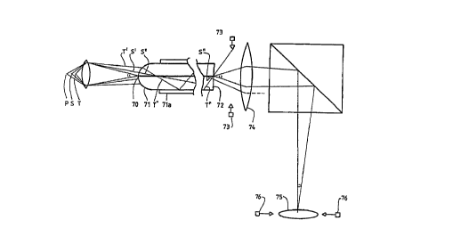
tip. Referring now to Figure 7, there is ~hown ~art of the
o~tics of one of the secon~ class of em~o~; ~nts which uses
the clA~;n~ modes by co~;n~ the distance from the axis
into incidence angle of propagation within the c~ ;n~.
Rays emerging from the confocal point P are shown entering
the 8 in~le mode core at 70 (exaggerated angle). The
collection ena 71 of the fibre is fashioned into a curved
sha~e to provide a lensing effect which bends ra~ to a
greater extent the more aistant they enter from the optical
axis. The confocal light effectively enters the core end
70 without refraction, ~ince the curved ~ha~e is behind the
core end 70. This shape may be m~ufactured by heating the
end of the fibre 80 that soften;ng and surface tension
produces a curved shape. Light emerging from points S and
T progressively farther from the focal plane enter~ along
rays S' and T' progressively farther from the o~tical axis,
and therefore corresponds to rays S'' and T'' of increasing
angle of propagation. Jacket 7la is composed of a suitable
low RI material such as silicone plastic. At an emission
end 72 of the fibre, the distance from the axi~ at which
the rays S'' and T'' emerge is not oraered in accordance
with the angle of propagation, but the angle of emergence
is 80 ordered. This can be use~ to a~vantage by ~rovision
of far-fiel~ iris ~;Arh~agm 73 in front of the near
confocal focusing means 74, which also may act a~ the laser
focussing optics. In a fully opened position the iris
~;~rh~agm admits substantially all of the light e~erging
from the emission end 72, which is then focused onto an
image of the fibre tip at detection focal plane 75. A
further near-field iris ~;~rh~agm 76 in front of the
detection focal plane 75 will not operate in a progressive
m~nn~n gimilar to irig ~;~rh~agm 73 since the spatial
variation of intensity in a projected image of the fibre
end i~ not correlatea in this embodiment with distance from
the axis of entering light, but may be used to exclude the
near confocal light from entering the photo detector when
CA 022l~97~ l997-09-22
W096/30796 PCTtAU96/OOlS9
- 15 -
operating at maximum resolution to detect only confocal
light. When the far-field iris ~;~rh-agm 73 is partially
o~ened, the near-field iris ~i~h~a~m 76 will vary the
proportion of near confocal light being admitted.
-
It may be advantageou~ to provide a section near the tip ofthe fibre having re~c~ overall diameter (not shown) by
hydrofluoric acid etching or other techniques so that the
radius of curvature of the tip can be decreased to give a
reduced ~ath length ~or the required separation of the near
confocal light. This section may be reduced in diameter in
a single step or gradually as an ~ h~tic taper.
Referring now to Figure 8, there is shown an alternative
means of extracting the near confocal light from one of the
secon~ class of embo~; - ts which uses cl~;ng mode
propagation. A glass block 80 is optically connected by
optical glue 81 to an ex~osed part of the cl~;n~ of the
fibre. The refractive index of the glass block must be
higher than or equal to the refractive index of the optical
glue which must be higher or equal to the refractive index
of the fibre clA~;~g. ~ens 83 focuses the light emerging
through variable iris 84 onto photomultiplier tube 85. A
mirror 86 reflects light emerging from the other side of
the fibre to follow substantially the same path. A
cl~;~g mode stri~per 87 prevents laser light from the
laser travelling along the cl~;n~. The confocal return
light travelling along the core of the ~ibre, which passe~
through the centre of lens 83 is extracted at the fibre end
in a st~n~d -~e~ and passed via beamsplitter 89 to
photo detector 88. In fluorescence imaging a~lications,
where the wavelength of the object emanate~ light differs
from the wavelength of the laser ~ource light, a laser
exclusion filter 890 can be u~ed to exclude any stray laser
source light which is reflected from the ti~ back into the
fibre as claading mo~es. Anti-reflection coatings or other
tip treatments could be employed without filter 890 if the
CA 022l~97~ l997-09-22
W096~0796 PCT/AU96/OOlS9
- 16 -
a~paratus i~ to be u~ed in reflection mode confocal
microscopy.
An alternative similar arrangement i~ shown in Figure 8A,
where a second glass fibre 8Al , preferably of larger
diameter ana the same or higher refractive index as the
c~;~ of the first ~ibre 8A2 (corre~ponding to the ~ibre
of Figure 8), i8 fused to the first fibre 8A2 over a length
of some millimetres. The light travelling down the ClA~;~
of first fibre 8A2 i~ chA~l led into the larger Recond
fibre 8Al in proportion to the cross-sectional areas o~ the
two fibres, and the angular ordering of the light rays i~
maintA;~e~. If a 500 micrometer fibre is u~ed for the
second fibre 8Al, and a 125 micrometer fibre for first
fibre 8A2, then approximately 94 percent of the cl A~
modes will be chAnn~lled into the second fibre 8Al. ~ens
8A3 and iris A;Arh~agm 8A4 may then be positioned remote
from fibre 8A2, ~Gving the need for encompassing the lens
around fibre 8A2.
Figure 8B show~ another alternative mean~ o~ providing the
variable ~election meang, where a material 8Bl of variable
refractive index is co~t~cted with an exposed part 8B2 of
the clA~;ng of the fibre (correspo~;~ to the fibre of
Figure 8). A variable amount of higher order mode~ can then
be extracted through surface 8B2 and discardea. The
~ ;~;~g complementary fraction passes to photomultiplier
tube 8B3. The material of variable refractive index may be
a collection of different liquias selectively being made to
contact the surface 8B2, or a series of soft polymer
blocks .
A further alternative similar arrany~ ?nt is shown in
Fiyure 9 where a perspex box 90 surrounds the ~ibre,
including a region contA;~;~g expo~ed cl~;~ at 92.
Clear polyester resin 93 is poured into the box 90 and
sets .
CA 022l~97~ l997-09-22
W096/30796 PCT/AU96/00159
- 17 -
Referring now to Figure 9A, there is chown an alternative
exit re~ion for embo~; nt~ of the second class. Rather
than have a single exit region as in the em~oA; - tq of
Figures 8 ana 9, whereby the selection means is provided by
lenses and irises, it is ~ossible to use succe~sive regions
of the fibre with the jacket 9A1 removed and drops of
optical glue with successively increasing refractive index
to cause ray~ of successively lower angle of internal
propagation to be extractea. If the cl~AA; n~ 9A2 typically
has a refractive index of 1.45 and the jacket 9A1 typically
has a refractive index of 1.40, in a first stripped region
a blob 9A4 of optical glue may have a refractive index of,
for example, 1.41 to extract a first portion of high angle
propagation ray~ into the glue in which i~ placea a photo
detector 9A3. At a second region optical glue 9A5 having
refractive index of 1.42 and detector 9A6 extracts further
light greater than a lower angle, and so on. As in the
emboA; ~nts shown in Figures 3 ana 4, l~nch moae strippers
are ais~osed at one end and switching mean~ ~rovide the
variable selection means (not shown). The blobs 9A4 and
9A5 are not to scale and are typically 3 to 4mm or more in
size, sufficiently long in an axial direction of the fibre
to extend at least as far as the internally reflecting ray
path "pitch".
A conventional objective lens may be used in place of the
curved fibre ti~ if the light is allowed to ~ro~agate on an
extended path to allow sufficient lateral divergence of the
near confocal light from the confocal light cone to thereby
produce the required coAi~ of lateral separation into
angular separation. The advantage of the curved fibre end
is that it allows for a much shorter di~tance between fibre
tip and specimen. Any arrany - t where the confocal
ch~nnel is disposed such that the confocal light is not
adversely refracte~ by the lens may be ~uitable to allow
short distance ~eparation between tip and specimen.
CA 0221~97~ 1997-09-22
W096/30796 PCT/AU96/00159
- 18 -
The integral f OCU8 ing providea by the curvea en~ 71 in
Fi~ure 7 may be pro~idea by se~arate ~mall lens ~luea onto
the fibre such as a ball lens 100 ~hown in Figure 10,
ty~ical ray ~aths 101 for which are shown. A di~aavantage
of this ~m~oA; - t is that the confocal light an~ the la~er
emission light is also focussea by the ball lens, again
requiring a larger aistance between fibre tip an~ sp~c;m~n.
This ~m~o~; - t also doe~ not correct for chromatic
aberration. However, one advantage is that relative
,v- ~nt between fibre tip and lens is maae possible. In
order to match the projectea laser beam to a variety of
lense~ in the micro~cope turret, each having a aifferent
back focal ~iameter it is aesirable to have an aajustment
mechAn;~m by mean~ of which the fibre tip entering the
heaa can be mo~ea towaras or away from the lens adjacent
the fibre tip. Figure 10A shows lens 10A1 attAch~ by a
flexible optical glue 10A3 to fibre tip 10A2 housea within
a piezoelectric cylin~er 10A4. The cylinder 10A4 i~
contractible in length, which shifts the fibre tip
longit~; n~1 ly by a few microns. This motion increase~ the
wiath of the light beam with negligible alteration in the
beam angle, ana after passing through the transfer optic~
this adjustment can be usea to match the aperture of the
objective lens being used, -~;~;~ing the optical
efficiency and resolution ~or each len~.
One of a thira class of embo~ 8 is shown in Figure 11
where insteaa of a lens on or in front of the face o~ the
fibre, a gradient index " - -~y profile" fibre i8 u8ea in
place of a ~ingle moae fibre. In this fibre, the optical
material surro~n~;ng the ~ingle moae core ha~ gra~ation~ of
refractive inaex, provi~ing a curvea ray path~ 110 for the
moae~ propagating in the fibre out~iae the core. Figure 11A
show~ a refractive inaex profile for the '~m~y profile"
fibre. Regions llA1 corre~pond to the polymer jacket,
regions llA2 to the gla~ clA~;ng, region llA3 to the
multimode-supporting region of gradation~ of inaex an~ llA4
CA 022l~97~ l997-09-22
W096/30796 PCT/AU96/OOlS9
-- 19 --
to the single mode core region. The ~Y; angle of
propagation of ray paths is related to the distance from
the optical axis at which the ray path enters as a ; n;
distance of approach of the ray to the outer face 111.
Thus, rays entering at a greater distance $rom the o~tical
axis have greater -~; angle of propa~ation as they
cross the optical axis and go closer to the outer face 111.
Thus progressive selection of the near confocal light by
means of a series of progressively ~eeper etchea regions
with optical glue at 112a, 112b and 112c is possible. The
diagram in Figure 11 of ray paths i8 schematic only. The
rays in fact do not enter the fibre in a -nn~ which would
cause the maintenance of node regions more than a short
distance along the fibre. Each etched region is in fact
not placed strategically with respect to a node, but is
elongate along the fibre axis for about 3 to 4mm, being
several times the pitch length of the oscillatory ray path,
whereby a single etched region on one side of the fibre to
a depth A will absorb effectively all light rays which come
within ~ of the sur~ace at their ~-~; of oscillation.
~eferring now to Figure 12, there is shown the emission end
120 of a gradient index fibre according to another
variation of the third class. A double iris diaphragm
arrany- - t similar to that shown in Figure 7 is employed
here, although the principle of operation is somewhat
different. The light emerging from the remote end of the
fibre is either far from the axis and has a low angle of
incidence such as rays 121 and 122, or is near to the axis
and has a high angle o~ incidence such as rays 123 and 124.
The light which proceeds to iris ~;~ph~agm 126 is light
which is emerging from the fibre at a low angle, aperture
125 block;~g out high angle light. This light is
approximately ordered in distance from the core in a
correspo~; ng -nn~ to the light entering the fibre, in
CA 022l~97~ l997-09-22
W096/30796 PCT/AU96/00159
- 20 -
turn corres~onA;~g to aistance from the focal ~lane in the
s~ecimen. For example, ray 121 is shown emerging slightly
further from the core than ray 122, ana is excluaed from
detection by the variable iris ~;Arh~a~m 126, while ray 122
i~ acceptea. The situation is more complex than this in
practice, h~cA~e the iaealisation of noaes depictea in
Figure 11 is not realised. This results in there being also
rays orderea in angle rather than aistance form the core,
and these may be progressively selectea by operation of
iris ~;Arh~agm 125. In practice, there is a conti~uous
range of int~ ?d;Ate cases also. The entire range can
however be progressively selected to an acceptable degree
by operating iris ~;Arh~agm 125 and 126 simultaneously.
The projected image of the fibre tip at iris ~;Arl~agm 126
i~ then displAc~ - t-codea from the axis in the desirea
-~n~, and its operation of the iris A; Aph~agm 126 is such
as to produce a variable pinhole effect for the near ~ield
modal pattern rays. Operatea in conjunction with variable
occlu~ion of the for field modal pattern rays by ris
~;Aph~agm 125 this will provide operation which i~
functionally equivalent to a conventional variable physical
pinhole in a confocal microscope system.
Still another arrang~ -~t in shown in Figure 13 where a
first fibre 131 is shown ca~t into a polymer block 132, the
surface 133 having been polished away to expose the
Cl A~;~g almost to the core 134. A variable amount of the
higher oraer moaes can then be extracted through surface
133 and discaraed by sliding a second polymer block 135
progressively over the surface 133, as is known analogously
in variable ratio fibre coupler technology.
In order to achieve appropriate separation of confocal and
near confocal light, it may be necessary in many
embodiments of the invention to use beam extenders in order
to provide an ade~uate distance between the fibre tip and
the objective while maintA;~;~g manageable product
,
CA 0221~97~ 1997-09-22
W096/30796 PCT/AU96/00159
- 21 -
ion~. Thi~ can be de3igned in a c~ _-5t r~c~e using
qt~ ~a o~posing mirror tech~;~ue~ as is well known in the
art.
The principle of coupling out modes from a fibre by means
of a su v~ 7;~ medium, the refractive inaex of which can
be changed, might also be applied to the light form the
la~er on the way to the microscope head. If a ~ew --~A
c ;cation~ fibre wa~ u~ed a~ the optical transmi~sion
meanC and the cl~;~g glas~ was etched away from a ~ection
of this fibre and replaced with a controllable variable RI
material then the modes passin~ into the microscope ~ould
be controlled at the same time as the mode~ c~~;~g back to
the detector~. Thi~ would have certain advantages in giving
extra ~ignal strength for low fluorophore concentrations
where there is fluorescence ~aturation and where non linear
bl~ Ch; ~ may be a problem.
Modifications may be made to the invention a~ would be
a~parent to a person skilled in the art of confocal optical
design. For instance, the invention i~ not restricted to
application~ re~uiring a diffraction-limited confocal spot
and imaging systems other than microccopes which can make
u e of the same optical principle~ are within its ~cope.
Further ~till, the near-field iri~ rh~agms which are
disposea adjacent a projected image of the fibre ena ana
it~ a~sociated photo detector may be replaced by CCD array~
if desirea and the selective exclusion of light per$ormed
in software. CCD arrays may similarly be u~ed with far-
f ield pattern decoaing.
Also, a number of embo~;me~t~ have been ~hown which
variously use exit regions in either a mia region of the
near confocal return ~ibre or an ena; ~election mean~ which
may be classifiea as ~near field" or "far field", being
composea of lenses an~ irise~ or switching mean~; ana
"coding~ ~ystems in three classes using isolated c
,
CA 02215975 1997-09-22
W096t30796 PCT/AU96/00159
- 22 -
or angular co~;~. Other combinations of these basic ideas
may be en~isagea ana are also within the scope of the
inve~t;~.
Further, as explA;~ above the single-fibre e_bo~;me~t
shown here can be replacea by dual fibre systems, with
~ource fibre and return fibre~ being separate or al~o with
the confocal return being provided by a separate fibre to
the near-confocal return. These and other moaifications may
be maae without aeparting from the ambit of the invention,
the nature of which i~ to be a~certA;~ from the foregoing
description ana the drawings.