Note: Descriptions are shown in the official language in which they were submitted.
CA 02216392 1997-09-24
Hardigg
96-1127
IMPROVED ELECTRONIC RACK AND MOUNTING FRAME
Background of the Invention
Loading and transporting sensitive electronic
equipment has presented numerous problems. Typically,
such equipment is packed in a suitable shipping container.
Even slight impacts or vibrations to the container,
however, produce shock forces that may damage precision
instruments if they are not properly supported within the
container.
To adequately protect electronic equipment, it is
well known to use heavy-duty containers molded from
polyethylene for high impact strength. An example of this
type of shipping container is disclosed in U.S. Patent No.
4,284,202 issued August 8, 1981 to Barstow Jr. It is also
necessary to build into these rugged containers a shock-
mitigation system that is capable of protecting the
equipment from possible damage during shipping and other
rough handling. One known system employs a mounting rack
constructed from a plurality of welded vertical and
horizontal frame members and shock mounts designed to hold
the electronic equipment stationary and to absorb shocks.
CA 02216392 1997-09-24
-2-
The problem with that prior art electronic rack
mounting frame is that the vertical and horizontal members
are Gas Shielded Tungsten Arc (TIG) welded together to
form an integral frame structure. Although the welded
rack frame is sufficiently strong to withstand most
impacts and transmit the forces produced thereby from the
shock mounts to the electronic equipment without damage,
there are difficulties associated with its construction.
First and foremost is the time required to weld the
various frame members together and to correct any
distortions caused during the welding process, which adds
considerably to the cost of manufacturing the mounting
rack. Because of imprecisions in the welding process, it
is difficult to maintain alignment of the mounting holes
which are used to secure the electronic equipment modules
to the rack. A further disadvantage of a welded rack
system is the storage space required to keep finished
racks in stock in order to fill orders promptly.
A more recent prior art electronic rack mounting
frame may be seen in U.S. Patent 4,998,636. While the
electronic rack mounting frame of this Patent is superior
to those mentioned above, it has been found that its
design requires numerous manufacturing steps and parts in
order to properly fabricate the frame. One drawback which
has been found is related to the use of threaded fasteners
in the patented rack. The front and the rear of the rack
are maintained in the desired rectangular shape by
threaded fasteners creating a frictional force among parts
by passing through a clearance hole in one part and into a
threaded hole in another part. Tightening the screw urges
the parts together. The problem (shape changing from a
rectangle to a rhombus) is in large part due to the
clearance hole which is larger in diameter than the
fastener passed therethrough. Because of the difference
in diametrical size, the only force holding the shape of
CA 02216392 1997-09-24
-3-
the unit is the frictional force created by the clamping
action of the threaded fastener; there is no structural
resistance against movement. As one of skill in the art
will readily recognize, moving the frame in shear against
only the frictional force created by the clamping force of
the fastener is orders of magnitude easier than moving the
parts by shearing the fasteners. Creating a rombus from
the intended rectangle is therefore relatively easy in the
prior art.
Out of square racks are not favored by the purchasing
industries and, therefore, are a drawback to the sales and
the reputation of the producer. Remedying the condition
is, therefore, desirable and important to the rack
mounting frame art.
Summary of the Invention
It is an object of the present invention to provide a
low-cost rack and mounting frame in which fewer parts and
less machining is required and where required labor for
assembly is reduced compared with rack and mounting frames
of the prior art.
It is a further object of the present invention to
provide a rack and mounting frame that is capable of
supporting electronic equipment modules inside a container
and preventing damage thereto caused by impact and
vibration during shipping and handling of the containers.
A further object of the present invention is to
provide a rack and mounting frame having frame members
that can be assembled quickly and easily in accordance
with precise dimensional tolerance and that can be
disassembled if desired.
It is yet another object of the invention to utilize
the shear strength of the fasteners to improve the
structural stability of the rack.
CA 02216392 2002-02-12
- 4 -
To accomplish these and other objects of the present
invention, the electronic rack and mounting frame
according to the present invention comprises a plurality
of vertical and horizontal frame members of identical
profile formed with a hollow interior, a plurality of
identical side frame members and a one-piece corner
connector for detachably securing the distal ends of
vertical and horizontal frame members to form a front
frame panel and a rear frame panel and for detachably
securing said side frame members to said front and rear
frame panels.
The vertical and horizontal frame members can be
made hollow throughout their entire lengths from an
extrudable, high tensile strength aluminum material. The
vertical frame members of the front frame panel have a
plurality of threaded mounting holes spaced a distance
corresponding to the spacing of a plurality of mounting
holes in the electronic equipment module that is to be
mounted to the frame. In general, the holes and spacings
are made up of units of three holes with 1/z inch, 1/a inch
and 5/8 inch between them respectively. This is dictated
by specification #EIA-310-D. In addition, the hollow
vertical and horizontal frame members have a
substantially rectangular cross-section such that the
frame members are defined by a front and a rear wall and
a pair of side walls.
The one-piece corner connector of the present
invention comprises an L-shaped device having a vertical
leg portion and a horizontal leg portion which are
disposed to one another at a right angle. Each leg
portion is joined together at said right angle at a
central portion. Said L-shaped device is also provided
with an L-shaped shoulder portion depending outwardly
CA 02216392 2002-02-12
- 5 -
from and in line with said leg portion. The horizontal
and vertical sections of said L-shaped shoulder portion
are connected to one another by a central portion which
is the same in shape as the central portion which
connects the leg portions of the L-shaped connector
device.
The distal ends of said leg portions of the L-shaped
connectors are internally received by the corresponding
hollow vertical and horizontal frame members which are
configured to substantially conform to the cross-
sectional shape of said leg portions.
The L-shaped shoulder portion of said corner
connectors is attachable via its outer surface to
similarly-shaped side frame members.
As should be clear to those skilled in the art, a
suitable rack and mounting frame may be produced using
eight corner connectors, four vertical frame members,
four horizontal frame members and four side frame members
wherein said corner connectors are identical as are the
vertical and horizontal frame members.
The rack and mounting frame, according to the
present invention, may include additional features such
as diagonally-extending frame members detachably secured
to the side frame members and/or a plurality of shock
mounts for supporting the frame within the hollow
interior of a transport container.
Therefore, in accordance with the present invention,
there is provided an electronic rack and mounting frame
comprising:
a plurality of horizontal frame members having two
ends and having at least two pinholes therethrough on
both ends thereof;
CA 02216392 2002-02-12
- 5a -
a plurality of vertical frame members having two
ends and having at least two pinholes therethrough on
both ends thereof;
a plurality of splice members, each splice member
being engageable with at least one horizontal frame
member and at least one vertical frame member, said
splice members further including pin holes alignable with
said at least two pinholes in each said horizontal frame
members and vertical frame members; and
a plurality of pins pressed into said pin holes when
said holes are aligned, said pins fastening said
horizontal frame members and vertical frame members to
said splice members.
Also in accordance with the present invention, there
is provided an electronic rack and mounting frame for
shipping and handling sensitive electronic equipment
modules comprising:
a plurality of hollow, substantially rectangular-
shaped vertical and horizontal frame members each having
two opposed ends and a plurality of pin holes;
a plurality of side frame members having two
opposing ends;
a plurality of internal splice members each securing
an end of one vertical frame member, one horizontal frame
member and one side member together, each of said
internal splice member including a horizontal leg portion
having pinholes therein and insertable into one end of
one of said horizontal frame members, a vertical leg
portion having pinholes therein and insertable into one
end of one of said vertical frame members and a shoulder
portion for receiving one end of one of said side frame
members, said pinholes in said splice members and said
pinholes in said frame members being aligned; and
CA 02216392 2002-02-12
- Sb -
a plurality of pins with one pin in each of the
aligned pinholes.
Still in accordance with the present invention,
there is provided an electronics rack and mounting frame,
comprising:
a plurality of horizontal frame members, each of
said horizontal frame members having two ends and having
a pinhole therethrough on both ends thereof;
a plurality of vertical frame members, each of said
vertical frame members having two ends and having a
pinhole therethrough on both ends thereof;
a plurality of splice members, each of said splice
members being engageable with one horizontal frame member
and one vertical frame member, said splice members
including pin holes alignable with said pinholes in each
of said horizontal frame members and said vertical frame
members;
a plurality of pins pressed into said pinholes when
said pinholes are aligned, said pins fastening said
horizontal frame member and said vertical frame member to
said splice members; and
wherein each of said splice members further includes
an integrally formed corner abutment, said corner
abutment having a first planar abutment for limiting the
engagement of said splice member with said horizontal
frame member and a second planar abutment for limiting
the engagement of said splice member with said vertical
frame member.
Other objects, features, and characteristics of the
present invention, as well as the methods, operation and
functions of the related elements of the structure and
the combination of parts and economies of manufacture,
will become more apparent upon consideration of the
CA 02216392 2002-02-12
- 5c -
following description and the appended claims with
reference to the accompanying drawings, all of which form
a part of this specification wherein like reference
numerals designate corresponding parts in the various
figures .
CA 02216392 1997-09-24
-6-
The above-discussed and other features and advantages
of the present invention will be appreciated and
understood by those skilled in the art from the following
detailed description and drawings.
Brief Description of the Drawings
Referring now to the drawings wherein like elements
are numbered alike in the several FIGURES:
FIGURE 1 is a perspective view of a prior art rack
and mounting frame installed within a shipping container;
FIGURE 2 is a perspective view of the prior art
mounting rack described and claimed in U.S. Patent
4,998,636;
FIGURE 3 is a perspective view of the assembled rack
and mounting frame of the present invention;
FIGURE 4 is an exploded perspective view of the
connection between the various frame members of the rack
and mounting frame of the present invention;
FIGURE 5 is a perspective view of the connection of a
side frame member to the shoulder portion of the corner
connector;
FIGURE 6 is a perspective view showing the attachment
of an electronic equipment module to the first panel of an
assembled rack and mounting frame of the present
invention; and
FIGURE 6A is an alternate method for attachment of
the equipment which the invention accommodates.
FIGURE 7 is a perspective view of the rack and
mounting frame of the present invention that has been
further strengthened with brace members.
Detailed Description of the Invention
FIGURE 1 is a representation of a prior art shipping
and storage container 10 which contains a rack and
CA 02216392 1997-09-24
_7_
mounting frame 12 for mounting electronic equipment
thereon. The electronic equipment 14 is provided with a
bezeled front panel 16 in which holes 18 are disposed for
securing the equipment 14 to the frame 12.
As shown in FIGURE 2 and fully-described in U.S.
Patent 4,998,636, the rack and mounting frame 12 is
constructed from a plurality of vertical and horizontal
members 20 and 22 and side frame members 24, all of which
are preferably made from extruded, high tensile strength
aluminum. The ends of each vertical 20, horizontal 22 and
side frame members 24 are affixed to one another at right
angles via an L-shaped internal splice member 26 and an
external splice (not shown) attached to one side of said
internal splice member 26.
As further shown in FIGURE 2, the side frame members
24 are provided with a pair of rubber shock mounts 28
which are disposed at a 45° angle to the vertical members,
in spaced relation, on each side frame member 24, running
in the fore-to-aft direction. The shock mounts 28 are
dimensional so that they engage brackets (not shown)
mounted inside the container 10, thereby suspending the
frame 12 within the hollow interior thereof.
While the rack and mounting frame 12 described above
was an improvement over prior art frames which were welded
together, said frame 12 has limitations of manufacturing
in that it requires different vertical and horizontal
frame members 20 and 22 which need expensive machining in
order to properly receive and hold the L-shaped internal
splice member 26.
The rack system 30, according to the present
invention, is shown in FIGURE 3 and is designed to
overcome the deficiencies in the prior art rack system
described above. Rack system 30, like the prior art
device of FIGURE 2, employs a rectangular, parallelpiped
frame structure comprising vertical and horizontal frame
CA 02216392 1997-09-24
_g_
members 32 and 34 and side frame members 36. The side
frame members 36 are provided with a pair of shock mounts
38, similar to those disclosed in connection with the
prior art device shown in FIGURE 2, for mounting the rack
frame 30 within the hollow interior of a transport
container.
The vertical and horizontal frame members 32 and 34
that make up the front and back frame panels 40 and 42 of
the rack system 30 are, preferably, extruded tubing most
preferably having a rectangular cross-section with hollow
interior 44 as illustrated in FIGURE 4. The tube may be
hollow throughout or merely may have a receptacle end
portion and otherwise be solid or otherwise obstructed.
While both the horizontal and vertical frame members 32
and 34 are identical as far as their cross-section and end
configuration are concerned, the vertical frame members 32
are provided with a standard pattern of threaded mounting
holes 46. This standard pattern is dictated under EIA-
310-D for vertical members whereas it is not necessary for
the horizontal members to include these holes. The holes
46 extend the length of the front and rear walls 48 and 50
of frame members 32 for securing the front bezel panel of
an electronic equipment module to the frame. In general,
only the vertical frame members are employed to secure
equipment. It is possible, however, to employ the
horizontal members alone or in combination with the
vertical members. As one of skill in the art will
appreciate, however, horizontal members with no threaded
holes and only pin holes are preferable, due to the cost
of adding the unnecessary drilling and threading.
It should be noted that the front and back walls of
the vertical frame member are most preferably 0.25" thick
to provide sufficient screw thread length whereas the side
walls are 0.080" thick to minimize weight of the completed
rack.
CA 02216392 1997-09-24
-9-
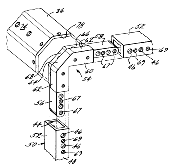
As shown in FIGURES 4 and 5, the vertical frame
member 32 and the horizontal frame member 34 are joined
together at their distal ends 52 via L-shaped internal
splice members 54. Each L-shaped internal splice member
54 comprises a vertical leg portion 56 and a horizontal
leg portion 58 which are disposed and joined at right
angles by a central portion 60 such that the outer face
surfaces 62 of leg portions 56 and 58 form a 45° angle
with the outer face surfaces 64 of the central portion 60.
The leg portions 56 and 58 have a rectangular cross-
section corresponding approximately to the cross-section
of the hollow interiors 44 of the vertical and horizontal
frame members 32 and 34. The central portion 60 has a
somewhat larger cross-section so as to provide abutments
for limiting the depth of insertion of the leg portions 56
and 58 into the vertical and horizontal members 32 and 34.
As also shown, the central portions 60 of the L
shaped internal splice member 54 are provided with a
shoulder portion 66 which extends outward from a side
surface 68 of the central portion 60. The shoulder 66
receives and supports one of the ends of side frame
members 36.
It should also be noted that the L-shaped internal
splice member 54 is identical for all eight corners so
that only one uniquely shaped member must be fabricated
for the invention.
To assemble the vertical and horizontal frame members
32 and 34 of the front and rear frame panels 40 and 42,
the vertical leg portion 56 of an internal splice member
54 is inserted into the hollow interior 44 of a vertical
member 36 and the horizontal leg portion 58 of said splice
member 54 is inserted into the hollow interior of a
horizontal frame member 34. Each leg portion 56 and 58 is
secured to the appropriate frame members 32 and 34 by
pairs of spiral pins 63 (FIGURE 5) which are inserted into
CA 02216392 1997-09-24
-10-
pin holes 69 in said members 32 and 34 which are aligned
with pin holes 67 in said leg portions 56 and 58. Spiral
spring pins are preferred for their high shear strength,
low insertion force, and ability to be inserted
automatically. Other pins, such as roll or solid pins,
could also be used. The spring pins used are headless and
have a length of less than the thickness of a member 32 so
that they may be wholly inserted into the pin holes 69 so
as to not interfere with holes 46 and/or bezel plate 70 of
an electronic equipment module 72 mounted to vertical
frame members 32 (FIGURE 6). Pins are superior to
threaded fasteners in this type of construction because
they do not require a clearance fit in one of the members
that they engage. The benefit of this is that the pin has
an interference fit with both members making shear
movements impossible unless the force exerted is beyond
the yield strength of the parts or the pins themselves.
Where in the prior art, friction was the only defense
against these movements. Thus, the ability of the frame
of the invention to withstand forces urging it out of
square are greatly increased.
The internal splice members 54 are machined to fit
closely in the vertical frame members 32 in the fore-to-
aft direction, but need not fit closely in the lateral
direction. Said splice members 54 are also machined to
provide a close fit inside the horizontal frame members 34
in the fore-to-aft direction, but not in the vertical
direction.
After all of the vertical and horizontal frame
members 32 and 34 have been assembled with internal splice
members 54 to make up front and rear frame portions 40 and
42 of the rack frame 30, the side members 36 are ready to
be assembled. As best illustrated in FIGURES 4, 5 and 6,
the side members 36 are made from metal strips having a
flat center portion 74 and outer portions 76 which are
CA 02216392 1997-09-24
-11-
bent at 45° angles with respect to the center portion 74.
The distal ends 78 of each side member 36 are attached at
each corner of the front and rear frame portions 40 and 42
by means of the shoulder portion 66. As noted in the
FIGURES, the shoulder portion 66 of internal splice member
54 is configured to match the configuration of the side
members 36.
The shoulder portion 66 is provided with a plurality
of threaded holes 80 which receive machine screws 82 which
are used to hold the side members in engagement with the
shoulder portions 66 of the internal splice member 54. As
clearly illustrated in FIGURES 4, 5 and 6, the thickness
of the side frame member corresponds to the depth of the
shoulder surface 66 below the outer face surfaces 62 and
64.
After all side frame members 36 have been secured to
the front and rear panel portions 40 and 42, electronic
equipment modules 72 can be mounted to the rack 30 as
shown in FIGURE 6. Each module 72 is provided with a
front bezel panel 70 which is an integral part of the
module 72. Holes 84, which follow EIA standards, are
provided in bezel panel 70 so that said holes 84 align
with threaded holes 46 provided along the front side wall
48 of the vertical frame member 32 and on the front of
splice-member 54. Screws 86 passing through holes 84 and
threaded into holes 46 secure the electronic equipment
module 72 to the rack 30. Depending largely upon the
weight of the equipment to be secured any number of the
threaded holes 46 might be employed.
The construction of the rigid rack frame 30 is
sufficient to withstand most impacts and vibrations
transmitted through the shock mounts while preventing
damage to sensitive electronic equipment secured thereto.
_ CA 02216392 1997-09-24
-12-
However, should it be desirable to further strengthen the
frame 30, diagonally-extending brace members 88 can be
attached in the pattern illustrated in FIGURE 7.
In addition to the substantial structural integrity
benefits of the invention, the invention is also
significantly less expensive to manufacture than prior art
units.
For example:
Prior Art Invention
5 unique extruded shapes 3 unique extruded
shapes
11 fasteners 7 fasteners
9 screws 3 screws
2 pins 4 pins
16 machine set-ups 11 machine set-ups
16 set-ups 11 set-ups
24 steps 15 steps
The cost savings of this manufacture is an important
advance in the art.
Although the invention has been described in
connection with what is presently considered to be the
most practical and preferred embodiment, it is to be
understood that the invention is not to be limited to the
disclosed embodiment, but, on the contrary, is intended to
cover various modifications and equivalent arrangements
within the scope and spirit of the appended claims, which
scope is to be accorded the broadest interpretation to
encompass all such modifications and equivalent
structures.
What is claimed is: