Language selection

Search

Patent 2216398 Summary

Third-party information liability

Some of the information on this Web page has been provided by external sources. The Government of Canada is not responsible for the accuracy, reliability or currency of the information supplied by external sources. Users wishing to rely upon this information should consult directly with the source of the information. Content provided by external sources is not subject to official languages, privacy and accessibility requirements.

Claims and Abstract availability

Any discrepancies in the text and image of the Claims and Abstract are due to differing posting times. Text of the Claims and Abstract are posted:

  • At the time the application is open to public inspection;
  • At the time of issue of the patent (grant).
(12) Patent: (11) CA 2216398
(54) English Title: ELECTRICAL CONNECTOR FOR ATTACHMENT TO A MEDICAL DEVICE
(54) French Title: RACCORD ELECTRIQUE POUR RACCORDEMENT A UN DISPOSITIF MEDICAL
Status: Deemed expired
Bibliographic Data
(51) International Patent Classification (IPC):
  • H01R 13/05 (2006.01)
  • H01R 13/35 (2006.01)
(72) Inventors :
  • HAWKINS, H. GENE (United States of America)
  • TESTA, VINCENT J. (United States of America)
  • HACKER, RANDALL L. (United States of America)
(73) Owners :
  • BOSTON SCIENTIFIC LIMITED (Barbados)
(71) Applicants :
  • BOSTON SCIENTIFIC CORPORATION (United States of America)
(74) Agent: SMART & BIGGAR
(74) Associate agent:
(45) Issued: 2005-07-19
(86) PCT Filing Date: 1996-04-18
(87) Open to Public Inspection: 1996-10-24
Examination requested: 2003-03-10
Availability of licence: N/A
(25) Language of filing: English

Patent Cooperation Treaty (PCT): Yes
(86) PCT Filing Number: PCT/US1996/005366
(87) International Publication Number: WO1996/033526
(85) National Entry: 1997-09-24

(30) Application Priority Data:
Application No. Country/Territory Date
08/425,085 United States of America 1995-04-19

Abstracts

English Abstract


An electrical connector (1) for attachment to a medical device. The connector
includes a
shaft of electrically conductive material having a proximal end (2) and a
distal end (3). Screw
threads (4) on the proximal end attach the connector (1) to the device. A
longitudinally extending
slot (6) extends from the distal end and forms two legs (7a) and (7b). A pair
of shoulders (8a)
and (8b) extend from the middle of the connector. The shoulders are adapted to
engage internal
walls of one type of female conector. A circumferentially extending recess
(9a) and (9b) is
disposed adjacent the distal end. The recess forms a head disposed distally of
the connector.
The recess is adapted to engage a ring disposed within another type of female
socket. The legs
are displaceable such that they provide spring engagement of the connector
within the female
connector by either the circumferentially extending recess or by the
shoulders.


French Abstract

L'invention porte sur un raccord électrique (1) destiné à être raccordé à un dispositif médical. Ce raccord comporte une tige constituée d'un matériau conducteur ayant une extrémité proximale (2) et une extrémité distale (3). Des filetages de vis (4) sur l'extrémité proximale rattachent le raccord (1) au dispositif. Une rainure longitudinale (6) part de l'extrémité distale et définit deux branches (7a) et (7b). Une paire d'épaulements (8a) et (8b) part du milieu du raccord. Ces épaulements sont conçus pour venir en contact avec des parois intérieures d'un type de raccord femelle. Un évidement de forme circulaire (9a) et (9b), adjacent à l'extrémité distale, forme une tête située à l'extrémité distale du raccord. Cet évidement est conçu pour entrer en contact avec un anneau situé dans un autre type de douille femelle. Les branches peuvent se déplacer de telle sorte qu'un accouplement élastique du raccord dans le raccord femelle soit assuré, soit par l'évidement de forme circulaire, soit par les épaulements.

Claims

Note: Claims are shown in the official language in which they were submitted.


5

CLAIMS:

1. An electrical connector for attachment to a
medical device, said connector comprising:
a shaft of electrically conductive material having
a proximal end, a distal end and threads disposed on said
proximal end;
a longitudinally extending slot extending from the
distal end of said connector, said slot forming two legs of
said connector;
a hex nut disposed between said proximal end and
said longitudinally extending slot;
electrical engaging means extending from the
middle of said connector, said means being formed of at
least two shoulders extending from the legs of said
connector, said shoulders being adapted to engage internal
walls of a female connector;
a circumferentially extending recess disposed
adjacent the distal end of said connector, said recess
forming a head disposed distally of said recess, said recess
being adapted to engage a ring disposed within the female
connector;
said legs being displaceable such that said legs
provide a spring engagement of said connector with the
female connector by either said circumferentially extending
recess or by said shoulders.
2. The connector according to claim 1 wherein said
legs are splayed outwardly from each other to improve
mechanical and electrical connection between said connector
and the female socket.

Description

Note: Descriptions are shown in the official language in which they were submitted.


.~, n .l~Ilmm., , ,all-.N Ive~l.l.~n....4. y.
CA 02216398 2005-04-19
77984-14
1
ELECTRICAL CONNECTOR FOR ATTACHMENT TO A MEDICAL DEVICE
Field of the Invention
The present invention relates to electrical
connectors for attachment to medical devices and especially
a dual function male electrical connector for attachment to
a cautery connector for endoscopy, especially endoscopic
snares.
Summary of the Prior Art
Electrical connectors for cautery endoscopic
snares are well known to the art. Such connectors, however,
are not readily usable with power supplies from different
manufacturers. Since operating rooms use power supplies
manufactured by different manufacturers, and these different
manufacturers use female connectors of different
constructions, it has been necessary for manufacturers of
endoscopic devices to stock and maintain male connectors
which are suitable for each of the power supplies currently
on the market. For example, with one of the manufacturers,
the female connectors require male connectors which have
shoulders about their midpoints to engage the interior
surface of the female connector and provide an electrical
connection. With another manufacturer, the female connector
requires a male connector having a circumferentially
extending recess disposed adjacent the distal end of the
connector. In this latter case, the recess in the male
connector engages a ring within the female connector. Both
of the connectors provide resilient electrical and
mechanical contact with the inner surface of the female
connector.


CA 02216398 2005-04-19
77984-14
2
Summary of the Invention
According to the present invention we have
discovered an electrical connector for attachment to a
medical device.
According to a broad aspect the present invention
provides an electrical connector for attachment to a medical
device, said connector comprising: a shaft of electrically
conductive material having a proximal end, a distal end and
threads disposed on said proximal end; a longitudinally
extending slot extending from the distal end of said
connector, said slot forming two legs of said connector; a
hex nut disposed between said proximal end and said
longitudinally extending slot; electrical engaging means
extending from the middle of said connector, said means
being formed of at least two shoulders extending from the
legs of said connector, said shoulders being adapted to
engage internal walls of a female connector; a
circumferentially extending recess disposed adjacent the
distal end of said connector, said recess forming a head
disposed distally of said recess, said recess being adapted
to engage a ring disposed within the female connector; said
legs being displaceable such that said legs provide a spring
engagement of said connector with the female connector by
either said circumferentially extending recess or by said
shoulders.
In a preferred embodiment, the slot is between
about 0.015 and 0.050 inches wide and the legs are splayed
outwardly somewhat at their distal end to make them urge
against the female socket to provide spring-action
engagement.

h r r,*oh..rr~ r e~iil.~N.lirr4ni....,r .~h,r
CA 02216398 2005-04-19
77984-14
2a
Thus, irrespective of the female socket to be
attached to the connector, efficient mechanical and
electrical contact can be made.
Brief Description of the Drawing
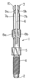
Figure 1 is a side elevational view of the
electrical connector for attachment to a medical device of
the present invention.
Figure 2 is a side elevational view, partially in
cross-section, of the electrical connector shown in Figure 1
disposed in one type of female connector.
Figure 3 is a side elevational view, partially in
cross-section, of the electrical connector of the present
invention disposed in another type of female connector.
Figure 4 is a top plan view of the electrical
connector shown in Figure 1.
Figure 5 is a perspective view of electrical
connector of the present invention attached to a cautery
polypectomy snare.


CA 02216398 1997-09-24
WO 96/33526 PCT/US96105366
3
Description of the Preferred Embodiments


Referring now to Figure 1, the electrical connector 1


of the present invention is formed of a brass shaft having a


proximal end 2 and a distal end 3. The proximal end 2 has


conventional threads 4 disposed thereon for securing the


connector into the medical device. A conventional hex nut 5


is formed between the ends of the threads 4 and the body of


the connector 1 for attaching the connector to the medical


device. The distal end of the connector has a diametrically


extending, longitudinal slot 6 formed in it. The slot is


between about 0.015 and 0.050 inches wide and extends from


the distal end of connector 1 to adjacent the hex nut 5.


The slot forms two legs 7a and 7b in the connector 1.


Normally these legs are splayed apart and when squeezed


together during use they exert a force against the insides


of the female connector in which it is fitted.


A pair of shoulders 8a and 8b are disposed at about the


middle of the connector 1. The shoulders 8a and 8b will be


used to establish mechanical and electrical connections as


will be explained later. A circumferentially extending


recess 9a and 9b is disposed adjacent the distal end of the


connector 1. The tip of the connector 1 is formed as a


head 10, split by the slot 6.


Referring now to Figure 2 the connector of the present


invention is shown disposed in one type of female socket.


As shown, the female connector includes an electrically


conductive material 11 disposed within an electrically


insulated cover 14. An internal ring 12 formed of the same


material as the connector material 11 is disposed within the


female connector. When the distal end 3 of connector is


squeezed into the ring 12, the legs 7a and 7b will squeeze


together to allow entrance of the head 10. When inside, the


recesses 9a and 9b engage the ring 12 and hold the connec-


tor 1 in place.


Referring now to Figure 3, the male connector shown


disposed within a different type of female connector. In


n i ~ ~.a~.:n.,~~. ~ ,.v.ii~:"~»~,w,.n...H.~~
CA 02216398 2005-04-19
77984-14
4
this Figure the shoulders 8a and 8b engage an electrically
conductive surface 15. Surface 15 is generally cylindrical
in cross-section and is disposed within an insulating
cover 16. Again, the legs 7a and 7b provide the resiliency
for shoulders 8a and 8b to engage the interior of the
electrically conductive surface 15. In Figure 4 the slot 6
can be seen disposed between halves of the head 10.
Shoulders 8a and 8b extend from the side of the connector.
The hex nut 5 is disposed beneath shoulders 8a and 8b.
Referring to Figure 5, the electrical connector of
the present invention is shown attached to a cauterizing
endoscopic snare. The snare is of a conventional design and
includes a pair of finger grips 20 which ride in a track 21
to control a snare 24 disposed within and extending from a
sheath 23. The electrical connector 1 is shown mounted on
the finger grips 20. When the snare 24 is disposed about a
polyp, the finger grips can be retracted and the snare 24
will strangle the polyp and then cauterize the wound with an
electrical charge. The snare 24 is electrically connected
to connector 1.
It is apparent that changes and modifications may
be made within the spirit and scope of the present
invention, but it is our intention, however, only to be
limited by the scope of the following claims.

Representative Drawing
A single figure which represents the drawing illustrating the invention.
Administrative Status

For a clearer understanding of the status of the application/patent presented on this page, the site Disclaimer , as well as the definitions for Patent , Administrative Status , Maintenance Fee  and Payment History  should be consulted.

Administrative Status

Title Date
Forecasted Issue Date 2005-07-19
(86) PCT Filing Date 1996-04-18
(87) PCT Publication Date 1996-10-24
(85) National Entry 1997-09-24
Examination Requested 2003-03-10
(45) Issued 2005-07-19
Deemed Expired 2010-04-19

Abandonment History

There is no abandonment history.

Payment History

Fee Type Anniversary Year Due Date Amount Paid Paid Date
Registration of a document - section 124 $100.00 1997-09-24
Application Fee $300.00 1997-09-24
Maintenance Fee - Application - New Act 2 1998-04-20 $100.00 1997-09-24
Maintenance Fee - Application - New Act 3 1999-04-19 $100.00 1999-03-17
Maintenance Fee - Application - New Act 4 2000-04-18 $100.00 2000-04-03
Maintenance Fee - Application - New Act 5 2001-04-18 $150.00 2001-04-10
Maintenance Fee - Application - New Act 6 2002-04-18 $150.00 2002-04-02
Request for Examination $400.00 2003-03-10
Maintenance Fee - Application - New Act 7 2003-04-18 $150.00 2003-04-02
Maintenance Fee - Application - New Act 8 2004-04-19 $200.00 2004-04-19
Registration of a document - section 124 $100.00 2004-06-29
Maintenance Fee - Application - New Act 9 2005-04-18 $200.00 2005-03-14
Final Fee $300.00 2005-04-19
Expired 2019 - Filing an Amendment after allowance $400.00 2005-04-19
Maintenance Fee - Patent - New Act 10 2006-04-18 $250.00 2006-03-16
Maintenance Fee - Patent - New Act 11 2007-04-18 $250.00 2007-03-16
Maintenance Fee - Patent - New Act 12 2008-04-18 $250.00 2008-03-25
Owners on Record

Note: Records showing the ownership history in alphabetical order.

Current Owners on Record
BOSTON SCIENTIFIC LIMITED
Past Owners on Record
BOSTON SCIENTIFIC CORPORATION
HACKER, RANDALL L.
HAWKINS, H. GENE
TESTA, VINCENT J.
Past Owners that do not appear in the "Owners on Record" listing will appear in other documentation within the application.
Documents

To view selected files, please enter reCAPTCHA code :


To view images, click a link in the Document Description column. To download the documents, select one or more checkboxes in the first column and then click the "Download Selected in PDF format (Zip Archive)" or the "Download Selected as Single PDF" button.

List of published and non-published patent-specific documents on the CPD .

If you have any difficulty accessing content, you can call the Client Service Centre at 1-866-997-1936 or send them an e-mail at CIPO Client Service Centre.


Document
Description 
Date
(yyyy-mm-dd) 
Number of pages   Size of Image (KB) 
Abstract 1997-09-24 1 49
Claims 1997-09-24 1 37
Drawings 1997-09-24 2 40
Cover Page 1997-12-30 1 55
Description 1997-09-24 4 176
Representative Drawing 1997-12-30 1 4
Claims 2005-04-19 1 37
Description 2005-04-19 5 189
Representative Drawing 2005-06-28 1 7
Cover Page 2005-06-28 1 43
Assignment 1997-09-24 7 380
PCT 1997-09-24 9 318
Prosecution-Amendment 2003-03-10 1 40
Prosecution-Amendment 2005-05-11 1 11
Correspondence 2004-03-23 3 64
Correspondence 2004-04-02 1 15
Correspondence 2004-04-02 1 18
Correspondence 2004-04-26 1 19
Fees 2004-04-19 1 37
Assignment 2004-06-29 2 73
Correspondence 2005-04-19 2 55
Prosecution-Amendment 2005-04-19 7 232