Note: Descriptions are shown in the official language in which they were submitted.
CA 02216399 1997-09-24
W O96/31018 PCTrUS96/03867
- 1 -
AN ELLIPTICAL SATELLITE SYSTEM WHICH EMULATES THE
CHARACTERISTICS OF GEOSYNCHRONOUS SATELLITES
FIELD OF THE INVENTION
The present invention defines a communications system which
5 communicates between orbiting communications satellites and ground stations.
More specifically, the system uses special communications equipment that allows
low orbit elliptically-orbiting satellites to emulate the communication characteristics
that would be obtained from a geosynchronous sateilite system. This system allows
operation in a way which is similar to geosynchronous satellites, at a fraction of the
0 cost of geosynchronous satellites.
BACKGROUND AND SUMMARY OF THE INVENTION
Geosynchronous ("geo") satellites were first proposed by Arthur C. Clarke
many years ago for use with communication systems. Communication systems
include television, two way communications, surveillance equipment, weather
15 monitoring equipment and other similar equipment. geo satellites operate based on
the physical concept that a satellite, at the proper working radius, orbits the earth at
the same angular velocity as the earth's rotation. These satellites therefore appear
to be fixed relative to a point on the earth.
This arrangement allows an antenna on the earth to continually point at
20 the satellite. This facilitates use of the geosynchronous satellites for
communications applications.
The inventors of the present invention have noted a number of drawbacks
associated with geosynchronous ("geo") satellite systems. One major drawback is
the cost to raise a s~te"ite into a geo orbit. Geosynchronous orbit occurs at around
25 36,000 kilometers. The cost to boost the satellite into orbit is directly proportional
c to the height of the orbit. Therefore, it is expensive to boost a satellite into
geosynchronous orbit. This cost must be amortized over the lifetime of the satellite,
~ making geo satellites very expensive.
Another problem results from the geometry of coverage of a
30 geosynchronous satellite system. A three satellite geostationary satellite system
CA 02216399 1997-09-24
W O96/31018 PCTrUS96/03867
could have the satellites spaced equally along the equator, at 120~ intervals. Their
limit of visibility on the equator is c~lc~ ted from the relationship:
2 {cos (RE/ageO)} = 2 ~cos (6378/35786) =
2 {79.73 deg} = 159.47 deg,
where 6378 is the radius of the earth in kilometers, and 35786 is the radius out to
the geostationary ring. Taking difference between the above value and 120
degrees, it is clear that there is approximately 40 degrees of overlapping coverage
by two adjacent geo satellites for an observer on the equator. There will be even
less at greater latitudes.
0 Many global services, however, require world-wide transmission of their
il lru~ dLion to the whole world. Since each of the satellites only covers one part of
the world, some other way must be used to disseminate the information from the
source to the satellites covering the rest of the world.
The information begins its transmission at a link. That link transmits up
to the s~ ? in orbit, which then retransmits the infommation to communicate to, or
"cove~' one portion of the earth. The same information must also be transmitted to
another of the satellites to cover another part of the earth. The information is either
sent: 1) over a land line between the link on the earth and ground stations thatservice areas for the other satellite(s), or 2) via satellite-to-satellite transmission.
The land link requires additional equipment and expense. The satellite link alsorequires additional equipment, but in addition operates a transmission across the two
ends of the 42,000 kilometer equilateral triangle. This requires a transmission which
is some 70,000 kilometers long. This system requires a second antenna on each
of the satellites in addition to complicating control and pointing structure. Even then.
the long communication channel may cause noise in the channel.
One of the most difficult-to-solve problem results from the geometry of the
geosynchronous orbit. There is only one available orbital position ("band") for
geosynchronous satellites. This band is already saturated with satellites. Satellites
occupy the geo band with only 2~ of spacing therebetween. These are referred to
as orbital "slots". Most of the slots are now occupied, making it diffcult to find
CA 02216399 1997-09-24
W O96/31018 PCTrUS96/03867
positions for any more geostalionary satellites. However, other satellite locations
cannot be allowed to interfere with the communication to the geo satellites whenoperating at the same frequencies.
The system of the present invention obtains the advantages of
geosynchronous satellites without using the high altitude circular orbit normally used
for geo s~ tes. The present invention uses a plurality of satellites in orbits chosen
such that each desired point of coverage on the earth communicates with a different
satellite at dirr~ r~nt times, and in a direction of antenna pointing separated angularly
from any geo satellite(s), such that there is no radio frequency interference, even
when operating at the same frequency as a geo satellite. Thus, the present
invention alleviates the present "geo-slot" problem. The lower altitudes of the
present invention also lead to smaller link distances from ground-to-satellite and
from satellite-to-satellite, decreasing the power required due to path loss. These
lower altitudes also decr~ase the time delay which can be annoying in voice
transmissions. Thus, the present invention provides a unique solution to some ofthe problems of using geo satellites.
Brief Description of the Drawinqs
These and other aspects of the invention will be described with reference
to the accompanying drawings in which:
Fig. 1 shows a basic layout of the multiple elliptical orbits of the present
invention;
Fig. 1A shows a graphical depiction of the satellite's angular motion along
its orbit as a function of the semi-major axis of the elliptical orbit.
Fig. 2 shows a layout of the satellite communication equipment used
according to the present invention;
Fig 2A shows a flowchart of operation of the satellites of the present
invention;
Fig. 3 shows the characteristics of a basic ellipse;
t Figs. 4A4F show characteristics of the three-satellite orbit of the present
30 irvention;
CA 02216399 1997-09-24
W O96/31018 PCTrUS96/03867
Fig. 4G shows chdr~cleristics of this orbit which prevent interference with
geosynchronous satellites in an inclined orbit;
Fig. 4H shows characl~ lics of this orbit which prevent interference with
geosynchronous satellites in an equatorial orbit;
Figs. 5A-5E show characteristics of the five satellite orbit of the present
invention;
Fig. 6 shows an overall view of the ten satellite orbit of the present
invention;
Figs. 7A-7G show the positions of the satellites of the ten satellite
10 embodiment within their repeating ground tracks; and
Fig. 8 shows the operating elevation angles for the ten satellite orbit, and
their angular isolation from geo satellites.
Description of the Preferred Embodiment
The system of the present invention defines a communication system
15 including ground communication equipment and a special constellation of satellites
in elliptical orbits at lower ~Ititl ~des than those necessary for geosynchronous, which
simulate the characteristics of a geosynchronous orbit from the viewpoint of theground communication equipment on the earth. The inventors recoqnized that
satellites which orbit in certain elliptical orbits spend most of their time near the
20 apogees of their orbits: the time when they are most distant from the earth. These
satellites spend only a minority of their time near their perigee. For example, an
elliptical s~te"ite in a 12-hour orbit spends eight of those hours near its apogee. By
appropriately choosing characteristics of the satellite orbit, the satellite can be made
to orbit, during that time, at a velocity that approximates the rotationai velocity of the
25 earth. The present invention defines a communication system using a constellation
of satellites chosen and operating such that a desired point on the earth alwaystracks and communicates with a satellite at or near apogee.
Another important feature of the present invention is the recognition of
how this mode of operation of the satellite changes its power characteristics.
30 Geosynchronous satellites are used virtually 100% of the time (except when ineclipse) and hence their power supplies must be capable of full-time powering. This
CA 02216399 1997-09-24
W O96/31018 PCTrUS96/03867
means, for example, if the satellite requires 5 Kw to operate, then the power supply
and solar cells must be capable of supplying a continuous 5 Kw of power. The
satellites of the present invention, however, are not used 100% of the time. During
the perigee portions of the satellite orbit, the satellites are typically not using most
of their llans",il and receive capability and hence, the inventors recognized, do not
use a large part of their power capability.
The inventors of the present invention recognized this feature of the
satellites, and realized that the satellites could be storing the power that is being
produced during this time of non-use. Therefore, the inventors realized that the size
of the power supply could be reduced by a factor of the percentage of time that the
satellite is not used.
The power sources can be any known means, including solar cells,
nuclear reactors, or the like. If the satellite is used half the time, then the power
source need only be sized to provide half the power. At times when the satellite is
not being used, the power source provides power to a battery storage cell, whichholds the power in reserve for times when the satellite is being used.
Like geo systems, the satellite of the present invention is virtually
continuously in the same lo~lio". Unlike geo-based systems, however, the ground
comrnunication equipment of the present invention does not always communicate
with the same s~t~ tf~. The satellites move slightly relative to the earth, i.e. they are
not always precisely at the same point in their apogees. One important advantageof the present invention is that the one satellite at apogee later moves to perigee,
and still later to other locations overlying other continents and areas. Hence, that
same satellite can later communicate with those other areas. Therefore, this system
allows a store-and-dump type system. The information can be stored on board the
satellite and later re-transmitted when the satellite overlies those other areas. This
system also allows all the satellites in the array to communicate with the othersatellites in the constellation.
This system has a number of other distinct advantages. Importantly, the
- 30 system operation allows selecting specific geographic locations to be prefer~ntially
covered; for example, continents can be followed by the constellation to the
exclusion of other areas, e.g. ocean areas between the continents. The
CA 02216399 1997-09-24
W O96/31018 PCTAUS96/03867
--6--
communication equipment on the continent always communicates with one satellite
at apogee, although not always the same satellite. From the point of view of theground station, the satellite appears to hover over the ground.
This satellite system operates virtually like a geosynchronous satellite
system. Importantly, these satellites according to the present invention orbit at
about half the altitude of the geo systems. A geo orbit orbits at 36,000 miles altitude:
the virtual geo satellite orbits at average altitudes of 16-18,000 miles. Also, geo
satellites require "apogee motors", to boost them from their original orbits into the
final geo orbit. These apogee motors can double the weight of the satellite.
0 This yields a commu.,ic~ "s system which costs less dollars per launch
capability because of the reduced weight to boost and less size. Also, since the geo
satellites orbit at a higher altitude, they operate at a higher power, and use a larger
illul 1 ~ Lil Iy antenna, all other condiliol ,s on the ground being equal. These satellites
also have a much larger overall size. This size of the satellites increases as the
square of the distance. Therefore, the geo satellite needs to be at least twice as
large and twice as powerful as a low altitude satellite. The power supply
conservation t~chni1ues of the present invention allow the satellite to be made even
smaller.
The system al~o provides satellites with very hi-lh elevation angles.
Maximizing the elevation angle prevents interference with existing satellites such as
true geosynchronous satellites.
This is another feature of the present invention which allows these
satellites to operate in ways which avoid any possibility of interference with the geo
band.
2~ Another objective and important feature of the present invention is its
ability to re-use satellite communication channels. Regulatory agencies such as the
FCC allocate frequency bands by allocating a specific frequency band for a specific
purpose. The geo satellites, for example, receive an assignment of a frequency
band. Thereafter, the regulatory agency will consider that other satellites located in
the same orbital position can not use this frequency because of possibility of
interference. Hence, frequencies in adjacent bands which might interfere with that
assigned band will not be allocated for new satellite use. With the present invention,
-
CA 02216399 1997-09-24
PCTrUS96/03867
W 096/31018
--7--
there is a large angular separation between the geo-sats and those covered by the
invention. Thus, the same frequencies ca be . "~ ted anew. Another feature of the
present invention is the location of the earth stations and satellites in a way which
prevents il ~le, rer~:nce with the geo bands. Specifically, the present invention defines
5 embodiments using both inclined orbits and non-inclined (equatorial) orbits. The
inclined orbit embodiment of the present invention only communicates with the
ground sldliol)s when a line drawn between the ground station and current position
of the satellite will not intersect any point within x~ of the ring of geosynchronous
satellites, where x is the required separation between the communication for geo10 satellites and the communication for the satellites of the present invention. During
other times, the equatorial component of the communication is shut off. The satellite
only communicates when it is near apogee. During those times, the rotational
velocity of the satellite approximates the rotational velocity of the earth, and hence
the satellite tends to hang overhead relative to the earth.
For non-inclined (equatorial) orbits, the ground stations are placed in a
position such that the commu"ic~lio" does not intersect the ring of equatorial orbits.
The system is controlled by on-board processor 280, which determines
the position in the orbit and the steering of the antenna from various parameters.
Processor 280 carries out the flowchart shown in Figure 2a which will be described
20 herein.
The overall system is powered by power supply 290 which supplies power
to all of the various components and circuitry which require such power. Power
supply 290 includes a source of power, here shown as a solar array 292, and an
energy storage element here shown as a battery array 294. Importantly, according25 to the present invention, the solar array 292 is sized to provide only some amount
of power less than that required to power the satellite communication. The amount
by which the solar array can be less is called herein the power ratio of the device.
The power ratio depends on the kind of orbit that the satellite will have, and how long
the satellite will be transmitting during each elliptical orbit. The preferred power ratio
30 is 0.5: this will power a satellite which is communicating half the time, and the other
half the transmitter and receiver on board the satellite is off and the solar array is
providing power to charge battery 294.
CA 02216399 1997-09-24
W O96/31018 PCT~US96/03867
--8--
The flowchart of operation is shown in Figure 2a. Step 350 represents
controlling the a"l~i "~a. This requires that the processor keep track of the satellite's
position in the orbit. Step 352 determines if the sateliite is in a position in its orbit
where it is active (transmitting and/or receiving). If so, flow passes to step 354
where power is drawn from power supply and the battery. If the satellite is not
powered, then power is used to charge the battery at step 3~6.
The system also allows selective expansion of the communications
coverage by adding additional satellites into additional elliptical orbits.
The virtual geo satellite system of the present invention also enables
complete communications coverage of the earth without requiring a ground network.
The same satellite services all dirr~r~ "L portions of the earth at different times of day.
The coverage of the earth repeats over a 24 hour period. A preferred embodiment
receives information relayed from the ground, relays it to the earth area below it,
then stores the infommation, and later reads back the stored information to re-
transmit that same information to other areas of the earth. The system of the
present invention increases the satellite coverage at high density geographic
locations using fewer satellites than was possible with previous constellations by
fixing the satellite apogee passages over given geographic regions defined by both
longitude and latitude.
Integral values for mean motion of the satellites in the array ensures that
the ground track repeats on a daily basis. The ground tracks preferably repeat each
day so that the orbit apogee passes in the same location relative to the geographic
target area. This system maximizes the time of coverage and elevation angles forthat pass.
2~ Before describing the minimum satellite arrangement according to thepresent invention, the nomenclature used herein to descrioe the characteristics of
satellite orbits will be first described. The "mean motion" is a value indicating the
number of complete revolutions per day that a satellite makes. If this number is an
integer, then the number of revolutions each day is uniform. This means that theground tracks of the satellites repeat each day: each ground track for each day
overrides previous tracks from the preceding day.
CA 02216399 1997-09-24
W O96~1018 PCTnUS96/03867
.. _ g _
Mean motion (n) is conventionally defined as the hours in a day (24)
divided by the hours that it takes a satellite to complete a single orbit. For example,
a satellite that completes an orbit every three hours ~'a 3-hour satellite") has a mean
motion of 8.
The "elevation angle" ~ is the angle from the observer's horizon up to the
satellite. A satellite on the horizon would have 0~ elevation while a satellite directly
overhead would have 90~ elevation. Geo satellites orbit near the equator, and
usually have a 20-30~ elevation angle from points in the United States.
The "inclination" I is the angle between the orbital plane of the s~t~" ~e and
the equatorial plane. Prograde orbit satellites orbit in the same orbital sense
(clockwise or counter-clockwise) as the earth. For prograde orbits, inclination lies
between 0~ and 90~. Satellites in retrograde orbits rotate in the opposite orbital
sense relative to the earth, so for retrograde orbits the inclination lies between 90~
and 180~.
The "critical inclination" for an elliptical orbit is the planar inclination that
results in zero apsidal rotation rate. This results in a stable elliptical orbit whose
apogee always stays at the same latitude in the same hemisphere. Two inclinationvalues satisfy this condition: 63.435~ for prograde orbits or its supplement 116.565~
for retrograde orbits.
The "ascending node" is the point on the equator where the satellite
passes from the southern hemisphere into the northern hemisphere. The right
ascension of the ascending node ("RAAN") is the angle measured eastward in the
plane of the equator from a fixed inertial axis in space (the vernal equinox) to the
ascending node.
The "argument of perigee" is a value that indicates the position where
orbital perigee occurs. When using equatorial orbits, 0~ argument of perigee is used
for all the orbits. Inclined orbit arrays use non-zero arguments of perigee.
Arguments of perigee between 0~ and 180~ locate the position of perigee in the
northern hemisphere and hence concentrate the coverage in the southern
hemisphere. Conversely, arguments of perigee between 180~ and 360~ locate the
perigees to the southern hemisphere and hence concentrate the coverage on the
northern hemisphere.
CA 02216399 1997-09-24
W O96/31018 PCTAUS96/03867
-- 10 --
The preferred embodiment of the present invention evenly spaces the
axes of the el~ipses. The spacing between RAANs is called "S" and calculated by
S= 360/n = 120~.
The present invention positions the satellite cove.-age based on both
longitude and latitude of the desired conli. ,enlal area to be covered by the orbit. This
is done, first, by synchronizing the orbit apogee to pass over the targeted
geographical region for each successive satellite. We select a suitable value for the
mean anomaly, which is a fictitious angle relating to the elapsed time in orbit. 360~
represents the completion of the orbit. In this example, the mean anomalies are also
S = 120~ apart.
This "mean a,1or"aly" M relates the amount of time it takes the satellite to
rotate S~ around the earth (here 120~). The mean anomaly required for the 12-hour
satellites to rotate to S~ is 8 hours; two-thirds of a period. This corresponds roughly
to the amount of time the satellite remains in apogee.
Taking the initial satellite near apogee, therefore, (180~ mean anomaly)
the next sa~l'ite should be backed up by 240~. This means that after 8 hours that
satellite will be at 180~. Since 180~ minus 240~ is negative 60~ which equals 300~,
this is the value of mean anomaly M for satellite number 2. This system is used to
select values for the constellation in a similar manner for each succeeding satellite.
Arrays with more satellites ("higher order arrays") can also be made using
the same rules as those discusserl above. ~S~ -ccessively larger numbers of satellites
can be used to provide more coverage, more overlapping coverage, or smaller
integral mean motion values. As the values of M get larger, the eccentricity of the
ellipses become smaller. This is because the perigee altitude is fixed at about 500
km to avoid re-entry and decay into the earth's atmosphere; longer periods have
higher apogee altitudes greater supportable eccentricities.
Figure 1A shows how the satellite ellipse is selected to have an angular
rate in the plane of the equator, at apogee, which approximates the angular rate of
the earth. The dotted line in Figure 1A represents the angular rate of a geo satellite,
and hence at this angular rate a satellite would approximate the angular speed of the
earth. The ellipse is selected to have a semi-major axis length to set the minimum
angular rate of the satellite at apogee. At apogee, the satellite angular rate should
=--
CA 02216399 1997-09-24
W O96/31018 PCTrUS96/03867
- 11 -
approximate the lu~lional velocit,v of the earth. In reality, this rotational velocity will
be either a little faster or a little slower than the earth. At this time, therefore, the
satellite appears to hang relative to the earth.
All elliptical orbits, including those described herein, are also subject to
5 effects of long-term pertu, bdliol ,s. If effects of these long term perturbations are not
compensated, this could cause continental coverage to drift with the passage of
time.
These pertu,bdlio" effects are mainly effects from the Earth's J2 rotation
harmonic. The earth is not a perfect sphere; it actually bulges at the equator. This
10 c~lJses gravitational effects on objects which orbit the earth. For posigrade orbits
(i > 90~) the line of nodes will regress. For inclinations greater than critical(63.4~ > i > 116.6), the line between the perigee and apogee (line of apsides) will
regress; for other inclinations,
I < 63.4~ or I ~ 116.6, the line of apsides will progress. Exactly at the critical angles
1 = 63.4 or I = 116.6, the line of apsides will remain stable a very desirable feature
in maintaining apogee at a certain latitude. In the equatorial plane, the combined
effect of these two major perturbations cause the apogee to advance or move
counter-clockwise from the sense of looking down from the celestial north pole. All
of the s~ s in a given array design would be affected similarly. Fortunately, this
effect could be compensated by slightly increasing the period of each satellite in the
array by an amount which offsets the J2 perturbation. This affects the system bycausing a point on the earth to take a slightly longer time to reach the satellite's next
apogee arrival point. This effect is compensated by slightly increasing the satellite's
period. The advance of perigee is suppressed by setting the inclination at one of the
critical values.
A first embodiment of the invention uses N=3 satellites, where N is the
total number of satellites, preferably in the equatorial plane, to cover
N - 1 = 2 continents. The rules for spacing and phasing the satellites will be given
in the general form that can be used later for more complicated constellations or
- 30 arrays.
The mean motion integer sets the minimum number of satellites in the
array and nc the number of continents that are followed. Here nc = 2 provides a
CA 02216399 1997-09-24
W O96/31018 PCTrUS96/03867
-12-
satellite period equal to 12 sidereal hours. N (the minimum number of elliptic
satellites in the array) is determined by using the relationship N - nc + 1. Thus, N
= 3. This is the minimum number of satellites that need to be in the array; we can
also set the number of satellites in the array N to be any integer greater than n+1.
The apogee passage is synchronized over the targeted geographical
region, for each successive satellite, moving counterclockwise as viewed from the
c~lesti~l North Pole. This is accor. "~lished by selecting a sl lit~hl~ value for the mean
anomaly.
- Refineloenl~: Additional features augmenting the usefulness of the above
0 simpler version include:
1) Inclining the elliptical orbital planes at the critical inclination angles
(63.435 or 116.535~), with phasing to maintain a single repeating ground track. The
single repeating ground track for the si,.,~ ied non-inclined example above is simply
the line of the equator.
2) Taking advantage of the higher apogees in allowing more direct cross-
linking between satellites than with present low-altitude circular arrays. Usually, a
single cross-link suffices, even when the longitude difference between end points is
180~ (on the opposite side of the earth)
3) rlacement of apogees over a s~lected latitude and longitude for optimal
coverage of a potential market area. This is done through proper selection of all the
orbital parameters, with particular attention given to selectisn of argument of perigee,
~ ~.
First Embodiment
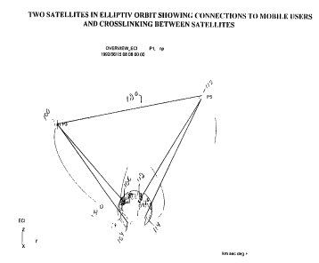
The orbits of the present invention are shown in Figure 1. The satellite
100 is shown in an elliptical orbit 102 around the earth. The communication
equipment on the satellite 100 communicates with earth ground station 104, and
also beams the infommation to earth ground station 106 Satellite 110 is shown in a
separate independent elliptical orbit communicating with ground stations 112 and114 on the earth. Note also that the satellite 100 can communicate directly to the
satellite 110 via communication link 120.
CA 02216399 1997-09-24
W O96/31018 PCTrUS96/03867
-13-
The preferred characteristics of these orbits are described in Table 1. TABLE I
Sat~;lite No. P1 P2 P3
Semi-Major Axis, a =26553.98km26553.98km 26553.98km
Inclination, l = 0 deg 0 deg 0 deg
Arg. Perigee, w= 270 deg 270 deg 270 deg
Eccentricity, e = 0.51 0.51 0.51
Rt. Ascension, i-2AAN=0 deg 120 deg 240 deg
Mean Anomaly, MA = 180 deg 300 deg 60 deg
Satellite 100 also includes store and dump hardware thereon as
desc,ibecl herein. This allows the satellite to obtain program information so that
later in its orbit, when at the position 130, it can send its same information to
ground station 132.
A detailed block diagram of the electronics in the satellite is shown in
Figure 2. This block diagram shows elements which carry out communication
between the ground station 104, the satellite 100, and the remote user station
1G6. ~~he inter-satellite links 120 are shown from the satellite 100 to the satellite
110.
The video input to be distributed is received as video input 200, and
input to a video coder 202 which produces digital coded video information. This
digitai coded video is multiplexed with a number of other channels of video
information by video multiplexer 204. The resultant multiplexed video 206 is
modulated and appropriately coded by element 208 and then up-converted by
transmitterelement210. The up~onverted signal is transmitted in the Ku band,
at around 14 GHz; by antenna 212. Antenna 212 is pointed at the satellite 100
and received bythe satellite's receive phased array antenna 214. Antenna 212
is controlled by pointing servos 213.
CA 02216399 1997-09-24
W O96/31018 PCTrUS96/03867
The r~cei\,ed signal is detected by receiver 216, from which it is input
to multiplexer 218. Multiplexer 218 also receives information from the inter-
satellite transponders 240.
The output of mulli,.~eY~r 218 feeds the direct transponders 250, which
through a power amplifier 252 and multiplexer 254 feeds beam former 256.
Beam fommer 256 drives a transmit, steerable phased-array antenna 260 which
llansil,ils a signal in a current geo frequency band to antenna 262 in the remote
user terminal 106. This signal preferably uses the same frequency that is used
by current geo satellites. The phased array antenna is steered by an on-board
0 computer which follows a pre-set and repeating path, or from the ground. This
il lfvi " IdliOil iS received by receiver 264, demodulated at 266, and decoded at 268
to produce the video output 270.
The satellite includes another input to the multiplexer from the
steerable antenna, via the intersatellite link 120 and receiver 240. Transmit
illrv""alion forthe the i"ler~alellite link is multiplexed at 242 and amplified at 246
prior to being multiplexed.
Output 222 of input multiplexer represents a storage output. The
satellite electronics include the capability to store one hour of TV program
information. The TV ch~nnels typically produce informati~n at the rate of 6
megabytes per second. The channels are typically digitally multiplexed to
produce il ~rvl m dLion on 4-6 channels at a time. Therefore, the present invention
preferably uses 22 gigabytes of storage to store over 1 hour of information at
about 4.7 megabytes per second. The information stored will be broadcast over
the next continent.
The storage unit 224, accordingly, is a wide SCSI-2 device capable of
receiving 4.7 megabytes per second and storing 22 GB.
Upon appropriate satellite command, the output of the storage unit is
modulated and up-converted at 226.
This basic system shown in Fig.2 can be used in one of the preferred
satellite arrays of the present invention. These arrays will be discussed hereinwith reference to the accompanying drawings which show the characteristics of
these satellite arrays.
CA 02216399 1997-09-24
W O96/31018 PCTrUS96/03867
-15-
This first embodiment ùses a simplified 12-hour equatorial plane
satellite array n=2, N=3. The mean motion n of 2 means that each satellite
completes an orbit around the earth twice per day.
- An important enhancement of an N=3 case is obtained by modifying
5 the characteristics of the orbits so that the satellites coalesce over the covered
areas at the moments when satellite coverage changes. The term coalesce as
used herein means that as one satellite moves out of range of the ground
tracking, the next satellite moves into range at that same position. In fact, the
two satellites come very close to one another at that point -- within 1 ~ from the
10 view of the satellite. This simplifies the ground tracking, since the switchover
between satellites does not require much antenna movement.
Figures 4A-4F show the basic three-satellite "rosette" formed by the
three elliptical orbits. The earth 300 is located at one of the foci of each of the
three ellipses of the respective satellites. Satellite 302 communicates with point
304 on the earth. Satellite 302 orbits the earth in ellipse 306. The satellites 1,
2 and 3 respectively have ascending nodes of 0, 120 and 240, and respectively
have mean anomalies of 180, 300, and 60.
Similarly, satellite 310 orbits the earth in ellipse 312, and satellite 320
orbits the earth in ellipse 322. Satellites 310 and 320 are both in a position to
provide coverage to the second covered continent area 314. Note that satellites
310 and 320 are in their co~lescerl position--they are very close positionally, to
one another. Satellite 320 is moving away from apogee while satellite 310 is
moving toward apogee. The tracking antenna is hence commanded to switch
between tracked satellites at the time when satellites 310 and 320 are
positionally very close, but having adequate angular separation to avoid self-
interference. According to the present invention, this switchover occurs when the
satellites are within 5~ of each other.
The satellites all orbit in a counter-clockwise direction relative to the
sense shown in Figure 4. The earth also orbits in the counter-clockwise
- 30 direction. The semi-major axes of the ellipses in Figure 4 are shown as axes
308, 314, and 316, respectively.
= =
CA 02216399 1997-09-24
W O96/31018 PCT~US96103867
-16-
ln order to describe these orbits, first the characteristics of an ellipse
will be described. Figure 3 shows ellipse 400, having a focus 402. The satelliteorbits along the path of the ellipse 400, with the center of the earth being at the
focus position 402 ("the occupied focus").
The apogee 404 and the perigee 406 of the orbits are defined by the
points on the ellipse which are farthest from and closest to the focus of the
ellipse, respectively. The amount of difference between these distances define
the eccentricity of the ellipse. The semi-major axis 408 is defined as half of the
long axis of the ellipse. This semi-major axis runs through the two foci of the
0 ellipse, to split the ellipse into two halves. The two lengths along the semi-major
axis, from one edge of the ellipse to the occupied focus of the ellipse are called
the "radius of perigee" and the "radius of apogee"; the latter being the longer.As the eccentricity of an ellipse approaches zero, the ellipse becomes
less elliptical, eventually approaching a circle (e=0) when the eccentricity is zero.
The semi-major axis of a circle is the radius of the circle.
The characteristics of the ellipse/ object in elliptical orbit are calculated
as follows.
-The apogee, ra = a ~ (1 + ECC).
Perigee rp = a ~ (1 - ECC).
20 A more eccentric ellipse (higher value of eccentricity ECC) has a greater
difference between the values P and R. Hence, such an ellipse is less like a
circle. The characteristics of the ellipse are therefore determined as a function
of its eccentricity.
The position of a satellite in orbit follows Kepler's laws of motion which
25 states that the orbiting element will sweep out equal areas of the orbit in equal
times. This results in the satellite moving very rapidly when it is at an
approaching perigee, but very slowly when it reaches apogee. For a twelve hour
elliptical orbit, therefore, it can be seen that the satellite will spend most of its
time near apogee. The numbers on the ellipse of figure 3 represent time
30 indications of hours passed in a 12 hour orbit, e.g., they indicate the number of
hours since zero that have e!~psed in a 12 hour orbit.
CA 02216399 1997-09-24
W O96/31018 PCTrUS96/03867
The prere"~d eliipse for the 3-satellite elliptical orbit has an eccentricity
of about 0.51. This value best allows the satellites to coalesce.
The earth rotates once in every 24 hour period, and hence takes eight
hours to rotate between the major axes of the three equally spaced ellipses
(120~ spacing). Figure 4A shows the point to be covered 304 is initially pointing
directly towards satellite 302 which is at apogee at time 0:00. As time passes,
both the satellite 302 and the earth will rotate.
As time p~sses, the satellites move from the position shown in Fig. 4A.
Fig.4B shows the position one hour later at time 1 :00. Satellite P1 has moved
away from apogee, although it has moved relatively little. Satellite P2, on the
other hand, is now moving much more rapidly at this time, since it is approaching
perigee, while P3 is still near the apogee position.
An observer on or near the equator sees the nearest satellite appear
to climb in altitude from almost directly overhead, towards apogee, all the while
staying almost directly overhead at an elevation angle of 80-90~. The satellite
is actually rotating more slowly than the earth during this time: it is appearing to
move from east to west, rather than west to east as most low or medium altitude
satellites move in the sky.
Fig.4C shows a view of the satellites one hour later at time 2:00. The
tracked locations 304 and 314 each still view a satellite near its apogee position.
Satellite P3 continues to move towards apogee and hence appears to hang
overhèad. P1 is still around apogee and thus also appears to hover.
Fig.4D shows yet another hour later at time 3:00. P3 is still at apogee,
but P1 is approaching perigee. Notice that P2 is coming out of perigee and
approaching the coalescence point at which P1 and P3 will cross paths. That
crossing of paths is shown in Figure 4E, time 4:00, when P1 and P2 have
coalesced in their positions at the time when point 304 switches over between
coverage by satellite P1 and P2. At that time, the satellites are within 1 ~ of one
another as viewed from the ground.
- 30 The above has described the satellite P1 moving from directly
overhead the point to be covered, to the point where satellite P1 no longer covers
CA 02216399 1997-09-24
W O96/31018 PCT~US96/03867
-18-
the point to be covered. Therefore, the satellite is transmitting for eight of the
twelve hours of its orbit; 2/3 of the time.
This cycle repeats. As the satellites continue to orbit, different
satellites take similar posiliGns to those shown in Figs. 4A4E. Fig. 4F shows the
cycle starting to repeat with satellite P2 moving toward apogee, satellite P1
moving toward perigee, and P3 hovering relative to the earth near its apogee.
Figures 4A-4F demonstrate the important features recognized by the
inventors of the present invention, whereby the satellites spend most of their time
at apogee. At the highest points of apogee, the velocity of the satellite very
0 nearly matches that of the earth, and so the satellite appears to hang overhead.
The satellite is pr~fer~bly tracked while its angular velocity differs from the earth's
angular velocity by 20% or less.
Importantly, the covered areas on the earth always see either a
satellite directly overhead or two satellites which are very nearly directly
overhead. Figures 4A4F show how this system actually appears to the
communications point 304 to be virtually geosynchronous. The communications
point commu"icales with different satellites at dfflerent times in the satellite orbit.
The communications point is always communicating with one satellite.
The satellites follow repeating ground tracks, since the cycle of satellite
movement shown in Figures 4A4F continually repeats. Importantly, this allows
the ground tracking antenna 212 to continually follow the same path, starting ata beginning point, tracking the satellite, and ending at the coalesce point. After
the satellites coalesce as shown in Figure 4A, the antenna begins its tracking
cycle.
The inventors of the present invention have optimized this system for
preventing interference with geo satellites.
Specifically, consider Figure 4G which shows a multiplicity of satellites
in inclined elliptical orbits. The present invention preferably operates to monitor
satellites at and near their apogee positions. The satellites near perigee are
moving too rapidly, and hence are not tracked. More generally, the system of thepresent invention operates such that the satellites are only being used at certain
times during their orbits. In this preferred embodiment, those certain times are
CA 02216399 1997-09-24
W O96/31018 PCT~US96/03867
-19-
when the satellites are at apogee. Non geosynchronous circular arrays are
co"""only used at present; they are actually much less efficient, since with zero
ecce,.l~icity they spend a significantly greater time on the side of the earth away
from the populated CG nlil ,enl~. The arrays of the present invention, on the other
hand, spend most of the time at or near apogee over the populated continents
of i,llt:r~ :sl, and a relatively small time (at high angular velocities) passing through
perigee in regions of no commercial interest.
The satellites are only used when their geometry is such that there is
no possibility of the line of sight between the ground station and the satellitei"l~,re,i,-g with the geosynchronous band of satellites. This allows the s~tellite
communication to take place on the same communication frequency band
normally assigned to geosynchronous satellites.
Moreover, the present invention teaches that when the satellites are
not communicating, either because the satellites are no longer at their tracked
apogee portion and/or when the satellites are in a region where they might
interfere with geosynchronous satellites, the main transmission is turned off.
During this time, the power supply is used to charge the battery. This means that
the power supply can be made smaller by some factor related to the duty cycle
of the satellite.
Another consideration is since the satellites only communicate while
near apogee, they are never eclipsed by the earth. The satellites can always
receive sunlight for solar operation while transmitting and receiving.
For example, Figure 4G shows satellites in orbit. In the example given
in Figure 4G, the satellites are only tracked when they are in the position of the
orbit above the line 450. The only possibility of interference with geo satellites
comes when the tracking beam is within 10~ to 30~ of the geo band. So long as
an angular separation greater than this amount is maintained, there can be no
interference. Therefore, the present invention allows re-using the frequency
bands which are usually assigned to geosynchronous satellites in a position
- 30 where interference with the existing satellites can not occur.
The same rules are used to construct higher order arrays with
successively larger integer mean motions and hence shorter periods. These
CA 02216399 1997-09-24
W O96/31018 PCT/US96/03867
-20-
arrays require a larger number of s~tellites, but provide somewhat better
coverage of the earth.
Since more satellites are used in these higher order arrays, each
satellite need spend a lesser amount of its time at apogee. This allows orbits to
be formed wherein the values of eccentricity are allowed to become smaller as
the mean motion increases. The ultimate limit is atmospheric drag, which limits
perigee altitudes to about 500 kilometers. This would correspond to a 1500
kilometer apogee elliptical orbit with a resulting eccentricity of
(ra - rp) / (ra + rp) which is approximately 0.067. This described orbit is not
10 practical since Ks period is about 1 hour and 45 minutes which is not an integral
value for the mean motion. The next nearest value for mean motion would be
n=14. The n=14 orbit, however, would be so slightly elliptic that it would not offer
much advantage over the circular orbits.
Practically, those arrays having mean motions of 3, 4, 5, 6, 7 and 8 are
15 most preferred according to the present invention. The most preferred orbits
according to this invention include the three-satellite orbits, the four-satellite
orbits, and the five-satellite orbits. A particularly preferred embodiment uses two
arrays of five satellite orbits.
As discussed above, all of these orbits include long-term perturbations
20 which would, if not compensated, cause the desired continental coverage to drift
offwith the passage of time. The two major perturbation effects are due to the
earth's J2 harmonic; and include:
- Regression of the line of nodes (for posigrade orbits), and
- Advance of perigee.
- For inclined orbits, the advance of perigee can be suppressed by
setting the inclination, i, at either 63.435 or 116.565~.
The combined effect of these two major perturbations in the equatorial
plane, due to the J2 harmonic term has the net effect of causing the apogee to
advance in a counter-clockwise direction looking down from the celestial North
30 Pole.). All the satellites in a given array design would be affected alike.
Fortunately, this effect can be compensated by increasing slightly the period ofeach satellite in the array in a way such that the earth takes a slightly longer time
CA 02216399 1997-09-24
W O96/31018 PCTrUS96/03867
-21-
to reach the next satellite's apogee arrival point. This is compensated by adding
this extra time to the satellites' periods. The exact amount will vary, and is afunction of a number of variables, including the orbital periods, inclinations, and
eccenl- icilies.
For inclined elliptic orbits, there will be no rotation of perigee in either
direction. However, there will be a r~yl~ssion of the line of nodes which must be
compensdted by a small adjustment in orbital period. This will cause the plane
of the orbit to rotate clockwise in the sense looking down from the North Pole.
If that happens, the satellite would pass over a selected meridian at a slightly0 earlier time each day (or each repeat cycle), unless we adjust the period of the
satellite. In this case, we would shorten the period of the satellite, which
effectively 'stretches' out the trajectory ground trace and causes the ground track
to repeat exactly over the life of the satellite.
As desc,i6ed above, third order effects due to tesseral terms may need
to be compensated by small orbit maintenance maneuvers using minuscule
amount of fuel.
The preferred four-satellite array is shown in Figures 5A-5E. This
array shows four satellites used to track three continents. These satellites orbit
in elliptical orbits having an eccentricity of 0.6. Figures 5B and 5D show the
20 satellite coalescing which occurs according to this preferred embodiment.
Figure 6 shows an overall view of the 10 satellite array; and Figures
7A-7E show the ground tracks for a satellite array with 5 satellites having a
period, T, equal to 6 hours. This array is preferably used with two sets of fivesatellites, yielding a ten-satellite, six hour constellation.
The preferred communications system uses a ten satellite system,
each having six hour orbits, and each optimized for users in the Washington, DC
area. This still, however, provides coverage throughout the rest of the
continental United States, and the entire northern hemisphere as well as that part
of the southern hemisphere down to about 10 deg South latitude.
The system uses ten equally-spaced proyrade satellite orbit p;anes.
All satellite orbits are at the 'critical' inclination ansle of 63.435~ to prevent
rotation of the line of apsides.
CA 02216399 1997-09-24
W O96/31018 PCTrUS96/03867
-22-
The ground track is adjusted so as to pass directly over Washington,
DC by adjusting the right ascensions of all the orbits while maintaining their equal
spac;. ,y. The argument of perigee is adjusted to obtain apogees over or nearly
over the targeted latitude and longitude.
Fig. 6 shows an overview of the orbital constellation. It can readily be
seen that the satellites favor the Northern Hemisphere by spending more time,
and reaching a higher altitude in the Northern Hemisphere. Figure 6 shows a
snapshot of time at 0:00 hours, and it should be seen that all satellites except for
satellites P5 and P1 are over the Northern Hemisphere at that time.
0 Figs. 7A-7G show a Cartesian, or Mercator, plot of the world showing
the repeating ground tracks. The satellite array has a repeating ground track that
repeats every 24 hours. The satellites appear to 'hover or dwell along four
equally-spaced meridians, one of which is at the longitude of Washington, DC;
the others being spaced at 90~ intervals from Washington.
Fig. 8 shows the minimum elevation angle to the highest satellite over
Washington, DC, as a function of time. Every 24 hour period has ten elevation
angle peaks of satellites on a descending (from north proceeding towards the
equ~tor) at or near the observer's zenith (90 deg). The lower, sharper peaks in
the figure represent other satellites on ascending passes: they are at lower
altitudes and thus going faster. These ascending satellites are not actively
transmitting to users on the ground at the times when they are on ascending
passes.
The preferred system uses a total of ten (10) satellites in critically-
inclined (i=63.4 deg) 6-hour orbits, phased and oriented to provide optimal earth
coverage. As will be seen, this geometry also provides a very high elevation
angle, and hence avoids interference with the existing geo communications
satellite band. The preferred orbits have apogee and perigee altitudes of 20074
and 654 kilometers, respectively.
From a user's viewpoint, the satellites are accessed sequentially at
nominal 2 hour and 24 minute intervals at exactly the same point in the
northwestem sky (the 'start point' of the tracking segment), and are tracked in a
roughly northwest to southeast trajectory to a point in the sky well short of
CA 02216399 1997-09-24
W O96/31018 PCTrUS96/03867
intersecting the geo band of satellites. The sdt~ s remain at apogee during the
time while they are being tracked from the ground. Hence, these satellites are
only tracked, and communicated with, while their velocity closely matches the
velocity of the earth. When the satellites begin to approach the perigee stage,
and hence their velocity increases relative to the earth's rotation to differ
therefrom by more than 25%, for example, they are no longer being tracked by
the communication equipment on the earth. At this end point of the tracking
segment, the ground communications antenna is directed back to tracking its
start point to repeat the sequence as the next-appearing satellite is acquired.
Tracking along the active arc segment is accomplished at less than 2 deg/min.
For the present array, this results in every ground communications antenna
err~cli"g ten switchovers per day. As explained above with reference to Figure
1, the steering operation of the present invention preferably uses phased array
steering of the antenna. However, more-conventional antenna steering is also
contemplated.
Importantly, the trajectory segments appear exactly the same to the
user for every satellite, since the azimuth-elevation trace is repeated for eachsatellite.
This system defines significant advantages. Its operating altitudes are
half that of existing geo systems. This greatly reduces link margins and emittedpower requirements for the satellites.
Apogees are placed on the meridians of longitude of the heavily-
populated areas for which the constellation is optimized. Apogee points may
also be adjusted to approximate the targeted area latitudes as well. The satellite
tracking arcs overthe targeted areas remain roughly overhead (within 3040~ of
zenith), with slow angular movement during periods when the satellite is active.The trajectories for mid-latitude (20-50~ North latitude) observers located directly
ur der the apogee points in the high-population targeted areas are approximatelynorth-south oriented.
- 30 All ten ground tracks are identical, and only the satellite that is
currently covering the repeating ground tracks change. The repeat cycle is 24
CA 02216399 1997-09-24
W O96/31018 PCTAUS96/03867
-24-
hours. Since the sateliites move from one geographic area to another,
information once transmitted can be re-broadcast at another location.
The Mercator plot of Figures 7A-7E show that the entire system
actually follows one ground track"~pedli"g after 24 hours. It actually 'folds over'
5 from the left edge of the world map to the right edge, giving it the appearance of
multiple traces.
Table ll gives the orbital parameters, or ephemerides, of the entire
array of ten satellites:
TABLE ll
SYSTEM ORBITAL PARAMETERS
Sat # a(km) i(deg)e,(ecc.) w,(deg) RAAN MA
(deg) (deg)
16742 63.435 0.58 315 0 0
2 16742 63.435 0.58 315 072 072
3 16742 63.435 0.58 315 144 144
4 16742 63.435 0.58 315 216 216
16742 63.435 0.58 315 288 288
6 16742 63.435 0.58 315 180 0
7 16742 63.435 0.58 315 252 072
8 16742 63.435 0.58 315 324 144
9 16742 63.435 0.58 315 036 216
16742 6;~.4350.58 315 108 288
CA 02216399 1997-09-24
W O96/31018 PCT~US96/03867
-25-
Some adjustments will be required to account for long term orbital
perturbations as described above. This adjustment is common in satellites
requiring precise repeat cycles such as Topex-Poseidon, or the Canadian
Radarsat.
Similar views to those from the above can be drawn for the preferred
ten-satellite array. An important point of the ten-satellite array, moreover, is that
there is good inter-satellite connectivity for cross-linking.
Fig. 7A shows the position of the satellites at time 00:00. Compare this
with Fig. 7B, which shows the same satellites twenty-four minutes later. The
0 satellite P4, which is substantially over Washington, D.C., has moved very little,
albeit P5 will be picking up speed as it approaches perigee. P4 appears to hang
over Washington, D.C., since it is near the apogee portion of its orbit and its
velocity very closely matches the velocity of the earth.
In contrast, during the same short period of time, the satellite P1, at
perigee, has moved very quickly and very far along its orbit. Similarly, satellite
P8 (over Europe), P5 (over Southern Africa) and P9 have moved very little.
Twenty-four minutes later, Fig. 7C shows that satellite P4 has started to move
away from the United States, but satellite P7 is now in place, very close to itsapogee. This is evident from its position twenty-four minutes after that, shown
in Fig. 7D, where s~lel'ile P7 has moved only very little, and is still well-covering
the United States. At time 1:36 shown in Fig. 7E, the satellite P7 is over
Washington, D.C.
The satellite P7 is still over Washington D.C. at time 2:00 hours, shown
in Fig. 7F. The satellite starts to move at time 2:24, shown in Fig. 7G.
2 5 The present invention intends that the satellites be used for
communication during only some part of the time while they are in orbit. During
other times in orbits, the satellites are not being used for communication, but
instead are charging their energy storage. This feature of the invention has been
- described above, but will be described in more detail herein with reference to
Figures 2A, 4G and 4H.
CA 02216399 1997-09-24
W O 96131018 PCTrUS96/03867
-26-
Figure 4G shows a view of the earth from, for example, the v,ew of the
satellite from the sun. This figure shows all of the satellite orbits, ar,d their
elliptical orbital paths. The geosynchronous satellites are in equatorial planesshown as the geo ring 800. Communications equiprnent on the earth
communicates with this geo ring 800. Moreover, sometimes the geo satellites
are perturbed by the earth's oblateness, hence effectively forming orbits which
are slightly inclined. The geo rings should therefore be considered at occupyinga 5~ position bordering their nominal position.
Ground communications equipment on the earth communicates with
o this geo ring. The cone of communications to the geo ring is shown as 802.
When the ground communication equipment on the earth
communicates with the satellites P1-P5, it should be seen that they are aimed
at a position of the sky, 804, which is completely separated from the geo ring
802. According to the present invention, a distance is maintained between the
satellites and the geo ring 800. The angular separation ~
is the minimum acceptable angular separation which can ensure no interference
between the geo ring and the satellites of the present invention. The preferred
embodiment uses an angular separation of 30~, which is an amount which will
obviate any possibility of interference problem. More generally, however, any
angular separation greater than 15~ would be acceptable.
Taking the satellite P3 as an example, therefore, the satellite can only
be used according to the present invention when it is in its orbit between the
points labelled 808 and 810. However, the virtual geo system which is preferablyused according to the present invention uses these satellites during even less of
their orbit, only between the points 812 and 814. When the satellite is in the
other positions of its orbit, the satellite is not consuming power or transmitting.
Therefore, this prevents any possibility of interference with the geo satellite
systems.
The operation of the equatorial satellites is similar. The equatorial
satellite array is shown in Figure 4h. The equatorial satellite is shown as satellite
ring 850. If the ground station is on the equator, shown as ground station 852,
then it would, at least at some times, interfere with satellites in the geo ring
CA 02216399 1997-09-24
W O96/31018 PCTrUS96/03867
shown as 854. However, if the ground station is separated from the equator by
at least 30~, such as shown as position 856, then at least part of the satellite ring
has no chance of interference with the ring 854. Therefore, the satellite
ca,culates geometries such as to obviate interference with the satellite ring.
Therefore, more generally, the present invention operates as shown
in Figure 2a. The antenna is co"l,ulled at step 35~, and from the antenna control
the position of the satellite relative to geo are determined at step 870. This can
be determined, for example, from the pointing angle of the antenna. Step 872
determines if there is any possibilit,v of interference between the two. This iso determined from a numerical difference between the pointing angle and the
position of the geo ring. If there is any possibility of interference, control passes
to step 874 where the satellite communications is disabled. If interference is not
possible at step 872, then the satellite is enabled at step 874. An enabled
.s~tr-II;l* can be, but is not necess~rily, tumed on. For example, in the virtual geo
embodiments, the enabled s~e!, te will be maintained in the "of~' position during
some of the time when it is enabled. Therefore, step 352 determines if the
satellite is powered. This may be determined from the repeating ground track,
or other information. If the satellite is not powered at step 352, the battery is
charged at step 356. If the satellite is powered, then power is drawn from both
the supply and the battery at step 354.
Although only a few embodiments have been described in detail
above, many modifications are possible in the preferred embodiment without
departing from the teachings thereof.
The above has described baseline arrays with simplified orbital
elements. It should be understood that the actual array may be rotated east or
west by any desired amount by adding or subtracting a constant angular offset
to each satellite's right ascension (RAAN). Additionaliy, other orbital parameters
such as argument of perigee (~) may be adjusted to improve performance a
dif.ferent market area.
- 30 All such modifications are intended to be encompassed within the
following claims.
,