Note: Descriptions are shown in the official language in which they were submitted.
CA 02216455 1997-09-24
DOCKET: 1845 PRO CANADA
APPARATUS FOR THERMAL TREATMENT OF TISSUE
BACKGROUND
1. Technical Field
The present disclosure relates generally to a method and apparatus for
thermal treatment of tissue and, more particularly, to an auxiliary apparatus
to be
used with a conventional endoscope to provide the endoscope with thermal
treatment
capabilities. The auxiliary apparatus is particularly contemplated for use
with a
cystoscope or a urethroscope for hyperthermia treatment of prostatic tissue.
2. Background of the Related Art
Benign prostate hyperplasia (BPH) or hyperplasia ai~ects over one out
of every two males over the age of fifty. BPH is the non-cancerous enlargement
of
the prostate gland and is characterized generally by a constriction of the
urethra by
the prostate gland. An array of symptoms are associated with BPH including
frequent urination, complications in urinary flow and associated pain.
Generally there are two primary methods for treating BPH, namely,
drug therapy and surgical intervention. Drug therapy incorporates the use of
one or
more drugs such as ProscarTM and HydrinTM to either reduce the size of the
prostate
or to relax the urethral muscles thereby facilitating the normal functioning
of the
urinary system. Known drug therapies, however, are limited in their
ei~ectiveness
and present many drug side effect concerns.
Surgical methods for treating BPH include transurethral resection of
2 5 the prostate (TURP), transurethral incision of the prostate (TUIP), visual
laser
assisted prostatectomy (VLAP), balloon dilation and stenting. TURF is the most
common method employed for BPH treatment today and involves the insertion of
an
electrosurgical cutting instrument through the urethral passage. The cutting
elements
of the instrument are positioned adjacent the prostate gland, and the
instrument is
3 0 energized such that the cutting elements selectively cauterize and resect
tissue from
the core of the prostate. The TURF procedure, however, has many side effects
CA 02216455 1997-09-24
-2-
including bleeding, retrograde ejaculation, impotence, incontinence, edema and
a
prolonged recovery period for the patient. An example of an electrosurgical
cutting
instrument utilized in conjunction with a TURF procedure is disclosed in U.S.
Patent
No. 5,192,280.
Transurethral incision of the prostate (TUIP) involves the use of an
electrocautery device which is passed through the urethra. The device is
employed to
make multiple incisions in the prostate, thereby permitting the prostate to be
displaced from the urethra wall to create an opening for urine flow. Success
with the
TUIP procedure is generally limited providing only temporary relief and
requiring a
1o subsequent repeat of the procedure in the future.
Visual laser assisted prostatectomy (VLAP) includes insertion of a
laser catheter through the urethra and directing laser energy laterally
through the
catheter sleeve at the urethral wall and the prostatic tissue. The laser
energy causes
the tissue to coagulate. The coagulated tissue eventually necrosis from lack
of blood
flow and is naturally removed from the body. Drawbacks of VLAP include
increased
recovery time, acute pain and irritation, and undesired burning of the
urethral wall.
Examples of methods and apparatuses utilized in VLAP treatment of BPH are
disclosed in U.S. Patent No. 5,242,438 to Saadatmanesh et al. and U.S. Patent
No.
5,322,507 to Costello.
2 0 Balloon dilation procedures for BPH involve expanding and stretching
the enlarged prostate with a balloon catheter to relieve pressure off the
constricted
urethra while stenting incorporates the insertion of tiny wire-mesh coils
which expand
into a scaffold to hold the urethra open. Balloon dilation and stenting,
however, are
only temporary procedures typically requiring follow up within a year period.
In
2 5 addition, stenting presents complications of stmt migration and consequent
irritation.
Transurethral microwave therapy (TUMT) and high intensity focused
ultrasound (HIFU) have been developed for the treatment of BPH. In accordance
with a TUMT procedure, a foley-type urethral catheter having a microwave
emitting
antenna at a probe end is inserted into the urethral passage for a period of
time
3 o suffcient to treat the tissue by microwave radiation. Intraurethral
applicators of this
CA 02216455 2005-O1-07
-3-
type are described in U.S. Patent Nos. 4,967,765, 5,234,004 and 5,326,343. The
drawbacks of TUMT include the inability to focus the heat energy in the
prostatic
area and the inability to achieve high temperatures uniformly within the
prostate.
High intensity focused ultrasound (HIFU) includes directing high
intensity ultrasound waves at the prostate tissue to create heat in a precise
area to
coagulate and necrose tissue. A transurethral probe is utilized to create the
ultrasound beams for both imaging and ablation of the prostatic tissue.
Disadvantages of this procedure include the inability to directly focus the
ultrasound
energy at the prostatic tissue.
to A more recent form of treatment for BPH involves thermally treating
prostatic tissue with radio frequency electromagnetic energy. For example, one
current technique, known as transurethral needle ablation (TUNATM), involves
the
transurethral application of a medical instrument having a built-in RF needle
electrode
system. The TUNATM instrument is inserted into the urethra and advanced to a
position adjacent the prostate. Thereafter, the RF needles are advanced to
penetrate
the urethral wall and access the prostatic tissue. The RF system is activated
whereby
a RF current is transmitted through each electrode to pass through the tissue
to a
grounding pad thereby forming a necrotic legion which is eventually absorbed
by the
body. Apparatuses and methods for treating BPH via the TUNATM technique are
2o disclosed for example in U.~. Patent No.: 5,366,490.
The TUNAT"" technique has ~everai aisadvantages which detract from its
usefulness. In particular, the TUNAT"" instruments are generally complex
typically
incorporating built in optical systems, aspiration systems, etc... As a
result, the
instruments are relatively expensive to manufacture. Moreover, the TUNAT"'
instruments are generally enlarged by virtue of the various systems
incorporated
within the instrument, thus, increasing patient trauma and discomfort during
use.
Accordingly, the present disclosure is directed to an auxiliary
apparatus for the RF thermal treatment of prostatic tissue. This apparatus is
intended
for use in conjunction with a conventional endoscope such as a cystoscope and
3 o incorporates an RF system and associated mechanism that is at least
partially
CA 02216455 2005-O1-07
-4-
positionable within the working channel of the scope. The apparatus by use in
conjunction with a conventional cystoscope makes use of the existing systems,
e.g.,
optical and illumination, of the scope, which effectively results in a less
complex and
less expensive RF thermal treatment device. Furthermore, the apparatus may be
used
in cystoscopes as small as 5mm (or even smaller) in diameter thereby providing
a less
invasive system for transurethral ablation as compared to the TUNAT""
instruments and
technique.
SUMMARY
An auxiliary electromagnetic thermal treatment apparatus for use with
an endoscope to provide the endoscope with electromagnetic thermal treatment
capabilities is provided. The auxiliary apparatus includes a handle portion
and an
elongate portion connected to the handle portion and dimensioned to be at
least
partially inserted within a working channel of an endoscope. The elongate
portion
includes at least one delivery tube having a memory portion comprised of a
shape
memory material and defining a normally unstressed curved configuration. The
one
delivery tube is longitudinally moveable relative to the handle portion to
extend the
memory portion beyond the working channel of the endoscope such that the
memory
portion assumes the normal unstressed curved configuration thereof. An
2 0 electromagnetic probe is disposed within the delivery tube and is
longitudinally
moveable relative to the delivery tube to extend a probe end portion thereof
beyond
the delivery tube and within tissue. The electromagnetic probe is adapted to
follow
the curved configuration of the memory portion of the delivery tube for
deployment
at an angularly oriented relation with respect to the endoscope. A rotatable
control
member is mounted to the handle portion and operatively connected to the
delivery
tube. The control member is rotatable to move the delivery tube between a
first
retracted position and a second advanced position. An actuator is also mounted
to
the handle portion and is operatively connected to the electromagnetic probe.
The
actuator is moveable to extend the probe end portion beyond the delivery tube.
CA 02216455 1997-09-24
-5-
The present disclosure is also directed to a combination of an
endoscope and an auxiliary thermal treatment device. A method for thermally
treating tissue is also disclosed.
BRIEF DESCRIPTION OF THE DRAWINGS
Preferred embodiments) of the present disclosure are described herein
with reference to the drawings wherein:
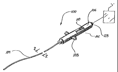
FIG. 1 is a perspective view of the auxiliary apparatus for thermal
treatment of tissue in accordance with the principles of the present
disclosure;
l0 FIG. 2 is a cross-sectional view taken along the lines 2-2 of FIG. 1
illustrating the outer sleeve, the probe delivery unit disposed within the
outer sleeve
and the electrodes disposed within the delivery tubes of the delivery unit;
FIG. 3 is a side elevational view of the probe delivery unit;
FIG. 4 is an axial view of the probe delivery unit as viewed from its
proximal end;
distal end;
2 0 unit;
FIG. 5 is an axial view of the probe delivery unit as viewed from its
FIG. 6 is a top elevational view of the probe delivery unit;
FIG. 6A is a perspective view of the distal end of the probe delivery
FIG. 7 is a side elevational of the handle of the apparatus of FIG. 1;
FIG. 8 is a cross-sectional view taken along the lines 8-8 of FIG. 7;
FIG. 9 is a cross-sectional view taken along the lines 9-9 of FIG. 7;
FIG. 10 is a top cross-sectional view of the handle illustrating the first
2 5 and second actuators of the handle;
FIG. l0A is an isolated view illustrating connection of the probe
delivery unit to the first actuator;
FIG. 11 is a side cross-sectional view of the handle further illustrating
the connection of the second actuating member to the electrodes;
CA 02216455 1997-09-24
-6-
FIG. 12 is a view illustrating insertion of a cystoscope with mounted
auxiliary thermal treatment apparatus within the urethral passage of the
patient;
FIG. 13 is a cross-sectional view taken along the lines 13-13 of FIG. 12
illustrating the apparatus of FIG. 1 positioned within the working channel of
the
cystoscope;
FIG. 14 is an enlarged perspective view of the distal end portion of the
cystoscope illustrating the delivery tubes of the probe delivery unit
contained within
the working channel of the scope;
FIG. 15 is a view illustrating distal movement of the first actuator to
1 o deploy the distal end portion of the delivery tubes of the probe delivery
unit;
FIG. 16 is a view similar to the view of FIG. 14 illustrating deployment
of the distal end of the delivery tubes of the probe delivery unit whereby the
distal
end assumes its normal unstressed condition angularly oriented relative to the
longitudinal axis of the apparatus;
FIG. 17 is a side plan view of the distal end of the cystoscope in partial
cross-section further illustrating deployment of the delivery tubes with the
electrodes
in a retracted position disposed within the tubes;
FIG. 18 is a view similar to the view of FIG. 15 illustrating distal
movement of the second actuating member to advance the electrodes through the
2 0 delivery tubes of the probe delivery unit and within the patient's
prostatic tissue;
FIG. 19 is a view similar to the view of FIG. 16 illustrating the
electrodes in the advanced position;
FIG. 20 is a view of an alternate embodiment of the auxiliary thermal
treatment apparatus where a greater portion of the electrode is exposed to
provide an
2 5 increased thermal treatment capacity;
FIG. 21 is a perspective view of another alternate embodiment of the
auxiliary apparatus for thermal treatment of tissue incorporating a coaxial
arranged
bipolar electrode assembly;
FIG. 22 is a perspective view with parts separated of the auxiliary
3 o apparatus of FIG. 21;
CA 02216455 1997-09-24
_7_
FIG. 23 is a side plan view of the apparatus with the handle in cross-
section;
FIG. 24 is a perspective view of the distal end of the elongate portion of
the apparatus;
FIG. 25 is a view similar to the view of FIG. 23 illustrating actuation of
the actuating portion to .deploy the electrode assembly beyond the directional
(delivery) tube of the elongate portion;
FIG. 26 is a view similar to the view of FIG. 25 further illustrating the
electrode assembly deployed from the directional tube;
FIG. 27 is an enlarged cross-sectional view of the distal end of the
electrode assembly and deployed beyond the directional tube;
FIG. 27A is an enlarged isolated view of the distal tip of the electrode
assembly with a thermocouple positioned therein for detecting the temperature
at the
treatment area;
FIG. 28 is a cross-sectional view taken along the lines 28-28 of FIG.
27A;
FIG; 29 is a cross-sectional view taken along the lines 29-29 of FIG.
27A;
FIG. 30 is a side plan view of the distal end of the directional tube with
2 0 portions cut away to depict a second thermocouple for detecting the
temperature of
tissue adjacent the treatment area;
FIG. 31 is a cross-sectional view taken along the lines 31-31 of FIG.
30;
FIG. 32 is a view illustrating insertion of a cystoscope and mounted
2 5 thermal treatment apparatus within the urethral passage with the
directional tube
partially deployed;
FIG. 33 is a view illustrating the cystoscope and mounted apparatus
inserted within the urethral passage with the directional tube fully deployed;
FIG. 34 is an enlarged view further illustrating the directional tube
3 o deployed;
CA 02216455 1997-09-24
_g_
FIG. 35 is a view similar to the view of FIG. 33 illustrating the
electrode assembly deployed beyond the directional tube and penetrating the
prostatic
tissue;
FIG. 36 is an isolated view further illustrating the electrode assembly
deployed within the prostatic tissue;
FIG. 37 is a view of an alternate embodiment of the auxiliary thermal
treatment apparatus of FIG. 21 incorporating a monopolar electrode assembly;
FIG. 38 is a perspective view of the distal end of the electrode assembly
with the monopolar electrpde deployed beyond the distal end of the directional
tube;
FIG. 39 is a cross-sectional view of the electrode illustrating a
thermocouple disposed within the electrode for detecting the temperature of
the
treatment area;
FIG. 40 is a side plan view of the electrode and directional tube with
the directional tube partially cut-away to illustrate a second thermocouple
for
detecting the temperature of the tissue adjacent the treatment area;
FIG. 41 is a cross-sectional view taken along the lines 41-41 of FIG.
40;
FIG. 42 is a side plan view of another alternate embodiment of the
auxiliary thermal treatment apparatus incorporating a dissipating agent for
facilitating
2 0 transfer of the electromagnetic energy to the treated tissue;
FIG. 43 is a view taken along the lines 43-43 of FIG. 42 depicting
components of the handle of the apparatus of FIG. 42;
FIG. 44 is a side plan view of the apparatus with the handle in partial
cross-section;
2 5 FIG. 45 is a side plan view of the distal end of the elongate portion with
portions of the directional tube and the electrode assembly cut-away;
FIG. 46 is a cross-sectional view taken along the lines 46-46 of FIG.
45;
FIG. 47 is a cross-sectional view taken along the lines 47-47 of FIG.
3 0 45;
CA 02216455 1997-09-24
_g_
FIG. 48 is a plan view of the handle illustrating a syringe connected to
the handle;
FIG. 49 is a view illustrating the cystoscope and mounted thermal
treatment apparatus inserted within the urethral passage;
FIG. SO is an isolated view illustrating deployment of the. electrode
assembly within the prostatic tissue; .
FIG. 51 is a perspective view of an alternate embodiment of a handle to
be utilized with the monopolar electrode embodiments of FIGS. 37-48;
FIG. 52 is a perspective view with parts separated of the handle of FIG.
S1;
FIG. 53 is a side cross-sectional view of the handle in an unactuated
position;
FIG. 54 is a side plan view of the handle of FIG. 51 mounted to a
cystoscope;
FIG. 55 is a view similar to the view of FIG. 53 illustrating rotation of
the control member to selectively deploy the delivery catheter; and
FIG. 56 is a view similar to the view of FIG. 53 illustrating the
deployment member advanced to deploy the electromagnetic probe.
2 o DETAILED DESCRIPTION OF PREFERRED EMBODIMENTS
The apparatus of the present disclosure is intended to deliver
electromagnetic energy to tissue for thermal treatment of the tissue including
tissue
ablation, tissue vaporization and/or tissue coagulation. The apparatus has
particular
application in the treatment of benign prostate hyperplasia (BPH) with
2 5 electromagnetic radio frequency (RF) energy, however, it is to be
appreciated that
the apparatus is not limited to such application. For example, the apparatus
is not
limited to the treatment of BPH, but, may be used in other surgical procedures
such
as cardiac ablation, cancer treatment, etc.... Moreover, the apparatus may be
used in
any minimally invasive procedure where thermal treatment of tissue is desired
and
3 0 access to the tissue is limited.
CA 02216455 2005-O1-07
y_
The apparatus is particularly intended to be used in conjunction with an
endoscope such as a cystoscope, fiber scope, laparoscope, urethroscope, etc...
to
provide the scope with thermal treatment capabilities. More specifically, the
apparatus is at least partially insertable within the working channel of an
endoscope,
which is positioned in the body to access a targeted tissue area, to thermally
treat the
desired tissue.
Referring now to FIGS. 1-2, apparatus 100 includes handle 102 and
elongate body 104 connected to the handle 102 and extending distally
therefrom.
Handle 102 includes frame 106 which is preferably fabricated from a suitable
rigid
1 o polymeric material or, in the alternative, from stainless steel or an
aluminum alloy.
Frame 106 is advantageously dimensioned to be grasped by the hands of the
surgeon.
Handle 102 further includes first and second actuators 108, 110 which are
mounted
for movement relative to the frame 106 to operate the apparatus.
Elongate body 104 may include outer sleeve 112 preferably fabricated
from a flexible material such as NitinolT"~. It is envisioned that outer
sleeve 112 may
alternately be rigid if, for.example, it is intended to be used with a rigid
scope. Outer
sleeve 112, if provided, ranges from about 25 to about 40 millimeters (mm) in
length,
preferably, about 37 mm and ranges from about I.S to about 2.5 millimeters in
diameter, preferably about 2.3 mm. Outer sleeve 112 defines axial bore 114
2 o extending therethrough. Other dimensions are also contemplated.
Alternatively, the
outer sleeve may be eliminated.
Referring now to FIGS. 2-6A, in conjunction with FIG. 1, probe
delivery unit, identified generally by reference numeral 116, is disposed
within axial
opening 114 of outer sleeve 112. Probe guide 116 is adapted for reciprocal
longitudinal movement within the opening I 14 and includes first and second
hollow
delivery (directional) tubes 118a, 118b. Delivery tubes 118x, 118b are
preferably
connected to each other for a major portion of their respective lengths, but
are
separated at the distal end portions 1~20a, 120b as best depicted in FIGS. 6
and 6A.
Delivery tubes 118x, 118b accommodate electromagnetic probes 122 therein (FIG.
2)
3 o and function in guiding the probes 122 at desired orientations within the
tissue.
CA 02216455 2005-O1-07
~1.1_
Referring particularly to FIGS. 3-6A, delivery tubes (or catheter) 118a,
1 I8b of probe guide 116 are preferably fabricated from a shape memory metal
such
as NITINOLT"" and are preferably joined to each other by welding or with the
use of
adhesives. In the normal condition of delivery tubes 118a, 118b, the distal
ends 120a,
120b of the tubes 118a, 118b each assume the arcuate configuration depicted in
FIGS. 3-6A, i.e., the distal end portions 120a, 120b have memory to define the
arcuate orientation as shown, thus, providing arcuate paths for
electromagnetic
probes 122 to follow to penetrate the tissue. The particular orientation of
memory
portions 120a, I20b of delivery tubes I 18a, 118b can be varied depending on
the
to objectives of the. surgical procedure. The distal end or memory portions
120a, 120b
of delivery tubes 118a, 118b readily adapt a linear configuration when
confined in the
outer sleeve 112 of elongated portion 104 as will be discussed.
In a preferred embodiment (e.g., in BPH application), memory portions
120a, 120b of delivery tubes 118a, 118b define a radius of curvature "r"
ranging
between about .250 to about .400 inches, preferably about .312 inches. Memory
portions 120a, 120b are also separated by an angle "T" ranging from about 45~
to
about 90~ (degrees). Clearly other dimensions and angular orientations of
memory
portions 120a, 120b are contemplated as well.
With reference again to FIG. 2, electromagnetic probes 122 disposed
20 within delivery tubes 118a, 118b include bipolar electrodes formed of a
thin solid
wire capable of carrying an electromagnetic radiofrequency (RF) current. The
electrodes are relatively flexible to follow along the path defined by
delivery tubes
118a, 118b, but, sufllcient in rigidity to be advanced into tissue. The
electrodes are
preferably made of Nitinol so they can return to their normally straight
configuratipn
after being bent by the delivery tubes. The electrodes each have a pointed tip
to
facilitate penetration through the tissue. Each electrode has an insulating
layer,
designated by reference numeral 124, which extends along a major portion of
its
length to prevent damage to non-targeted body tissue. Each electrode is
therefore
electrically isolated from its delivery tube. Insulating layer 124 terminates
to expose
3 0 the distal penetrating portions of the electrodes 122, thus, permitting
the transmission
CA 02216455 1997-09-24
-12-
of electromagnetic RF current to the targeted body tissue. Alternatively,
monopolar
electrodes could be provided.
Referring now to FIGS. 7-11, probe unit 116 extending through outer
sleeve 112 is operatively connected to first actuator 108. In a preferred
arrangement,
first actuator 108 includes an inner recess 125 which receives the proximal
end of
probe guide 116 in interfitting relation as depicted in FIG. 10A. Other
mounting
arrangements for connecting actuator 108 and probe guide 116 are envisioned as
well
such as the use of adhesives, screws, or the like. Longitudinal movement of
first
actuator 108 causes corresponding longitudinal movement of probe delivery unit
116
within outer sleeve 112. That is, first actuator 108 is moveable to cause
reciprocal
movement of probe guide 116 between a first retracted position where the
distal end
or memory portions 120a, 120b of guide 118a, 118b are contained within outer
sleeve 112 and a second advanced position where the memory portions 120a, 120b
extend beyond the distal end of outer sleeve 112 and assume their angularly
oriented
positions as will be discussed hereinbelow.
Second actuator 110 is operatively connected to electromagnetic
probes 122 disposed within delivery tubes 118a, 118b. Any conventional means
appreciated by one skilled in the art for connecting actuator 110 to
electromagnetic
probes 122 may be utilized. In the preferred embodiment, an interfitting
relationship
2 0 of the proximal ends of electromagnetic probes 122 with an inner recess of
second
actuator 110 (such as the arrangement disclosed above with first actuator 108)
will
be employed. Second actuator 110 is moveable to cause corresponding motion of
electromagnetic probes 122 within their respective delivery tubes 118a, 118b
to
extend the penetrating end portions of the probes 122 beyond the tubes for
2 5 deployment into tissue.
As seen in FIGS. 7, 10 and 11, a pair of conductive wires 126 are
provided to connect electromagnetic probes 122 to coupling 128 mounted to
handle
104. Coupling 128 is connectable to an external radio frequency energy source
"s" as
schematically depicted in FIG. 1.
CA 02216455 1997-09-24
-13-
Refernng now to FIG. 12, apparatus 100 is shown positioned within ~a
conventional cystoscope 200 for thermal treatment of prostrate "p" to
alleviate the
symptoms of BPH. One conventional cystoscope 200 with which the apparatus of
the present disclosure can be utilized is the ACN Flexible CystoNephroscope
manufactured by Circon ACMI. Cystoscope 200 includes handle 202 and a flexible
elongated portion 204 connected to the handle 202 and extending distally
therefrom.
Cystoscope 200 incorporates an optical system to permit viewing of the tissue
to be
treated. As depicted in FIG. 13, the optical system preferably consists of
flexible
fiber optic bundles (identified by reference numeral 206) which are
accommodated
within a longitudinal bore extending through the elongated portion 204 of the
scope
200. The fiber optic bundles 206 extend to eyepiece 208 where the surgeon can
view
the image transmitted by the optical system.
Cystoscope 200 also includes an illumination system which provides
illuminating light to the targeted tissue area. The illumination system
includes a
plurality of optical fibers 210 which are accommodated within a plurality of
longitudinal channels (two are shown) of elongated portion 204 and extend
within
handle 202 where they terminate at illumination coupler 212. Illumination
coupler
212 is connectable to a conventional light source as is known in the art.
Cystoscope
200 further includes a working channel 214 extending through flexible
elongated
2 0 portion 204 and terminating at channel port 216 of handle 202. Working
channel 214
is adapted to receive various surgical instrumentation through channel port
216 (e.g.,
thermal treatment apparatus 100) to permit the performance of surgical
procedures at
the distal end of the cystoscope 200. Cystoscope 200 is preferably a Smm
scope.
2 5 Operation
The use of apparatus 100 with cystoscope 200 in conjunction with the
thermal treatment of prostatic tissue will now be discussed. Cystoscope 200 is
inserted through urethral passage "u" of the patient and advanced within the
passage
until the distal end of the scope is adjacent prostate gland "p". Thereafter,
elongate
3 o body 104 of apparatus 100 is inserted into working channel 214 of
cystoscope 200
CA 02216455 2005-11-16
-14-
and advanced into the working channel 214 until handle 102 of the apparatus
contacts channel port 216 of scope handle 202. As an alternative method of
insertion, apparatus 100 may be positioned within cystoscope 200 prior to
insertion
within the urethra) passage "u" and the entire assembly may be then advanced
within
the urethra) passage. It is envisioned that handle 102 of apparatus 100 may
incorporate a locking mechanism to lockingly engage channel port 216 of handle
202
of the cystoscope 200.
With reference now to FIG. 14, probe delivery unit 116 is shown in its
retracted position. In such position, the distal end portions 120a, 120b of
delivery
1o tubes 118a, 118b are constrained by outer sleeve 112 (and elongated portion
204 of
scope 200) thereby assuming a general linear configuration within the sleeve
112.
Thereafter, first actuator 108 is distally advanced as depicted in FIG. 15 to
move
probe delivery unit 116 from its retracted position of FIG. 14 to its extended
position
of FIG. 16. Upon exiting working channel 214 of cystoscope 200, the distal
ends or
memory portions 120a, 120b of delivery tubes 118a, I 18b are no longer
constrained
by outer sleeve 112, and, thus are free to assume their normal unstressed
curved
configurations depicted in FIG. 16 and FIG. 16A. By exiting through the distal
end
face of the working channel 214 of cystoscope 200, the deployment of delivery
tubes
118a, 118b can be monitored with the optical system of cystoscope 200. That
is,
2 0 both 0 degree and oblique viewing is achieved. In the extended position of
delivery
tubes 118a, 118b, the distal end portions 120a, 120b may slightly extend
beyond the
outer circumference of scope 200, but, however, do not penetrate the urethra)
lining.
It is to be noted that the degree of deployment of memory portions 120a, 120b
of
delivery tubes 118a, 118b may be selected to thereby achieve desired angular
2 5 orientations of the memory portions 120a, 120b, consequently, controlling
the
orientation of the deployed electrodes. (As noted above, alternately, outer
sleeve
112 need not be provided and the apparatus is advanced through the working
channel
to expose the delivery tubes.)
Referring now to FIGS. 17-19, with distal end portions 120a, 120b in
3 0 their extended positions, attention is directed to deploying the
electromagnetic probes
CA 02216455 1997-09-24
-15-
122. FIG. 17 depicts the electromagnetic probes 122 in their retracted
position
within delivery tubes 118a, 118b. Second actuator 110 is selectively distally
advanced to advance electromagnetic probes 122 from delivery tubes .l 18a,
118b as
depicted in FIG. 18. During advancing movement, the penetrating end portions
126
of probes 122 flex or bend to conform to the curved configuration of memory
portions 122a, 122b of the delivery tubes 118a, 118b to pierce the urethral
wall "u"
and enter the prosthetic tissue "p". The degree of deployment of
electromagnetic
probes 122 may be selectively controlled (e.g., partial deployment) with
second
actuator 110 to thereby provide a level of control over the thermal treatment
field
generated by the probe.
The system is then energized to thermally treat (e.g., ablate, vaporize or
cauterize) the desired prosthetic tissue with RF energy. As a result of this
treatment,
the prosthetic tissue BPH necroses and dies, thus, relieving pressure ofl'the
urethral
wall and alleviating the symptoms of BPH. During treatment, the depth of
penetration of penetrating end portions 126 of electromagnetic probes 122 may
be
selectively adjusted by movement of second actuator 110 to permit specific
regions
of the prosthetic tissue "p" to be targeted for thermal treatment thus
providing
heating pattern flexibility and control. During treatment, insulating layer
124 of
electromagnetic probes 122 preferably contact the urethral wall "u" to prevent
2 o damage to the wall.
Upon completion of the procedure, the system is de-energized and the
cystoscope 200 and apparatus are removed from the urethral passage "u".
FIG. 20 is a perspective view of the distal end of cystoscope 200 with
an alternate auxiliary thermal treatment apparatus mounted within the working
channel 214 (FIG. 13) of the scope. This thermal treatment apparatus is
identical to
the apparatus described in connection with FIG. 1 except that in accordance
with this
embodiment, a greater portion or length of the inner electromagnetic probe 122
is
exposed (i.e., uninsulated) to increase the thermal treatment region generated
by the
probes (Compare with FIG. 19). It is to be appreciated that the lengths of the
CA 02216455 2005-11-16
-16-
exposed electrode portions i.e. the length of insulation, may be varied to
achieve
desired thermal treatment objectives.
Referring now to FIGS. 21-23, there is illustrated another alternate
embodiment of the auxiliary RF thermal treatment apparatus of the present
disclosure. Apparatus 400 includes housing or handle 402, elongate portion 404
connected to the handle and extending distally therefrom, and a bipolar or
monopolar
electrode unit 406 which extends beyond the distal end of the elongate portion
404.
Handle 402 includes frame 408 defining a generally cylindrical configuration
and
having diametrically opposed finger rings 410 mounted thereto. Finger rings
410
to accommodate the fingers of the user to facilitate holding and manipulation
of the
apparatus 400. Handle 402 further includes actuating portion 412 which is
mounted
to frame 408.
Actuating portion 412 includes a distal inner cylindrical mounting
section 414 which is received within an internal bore of frame 408 to mount
the
actuating portion 412 to frame 408. Mounting section 414 is dimensioned to
slide
within frame 408 thereby permitting relative movement between the two
components,
i.e., actuating portion 412 is reciprocally moveable relative to frame 408 to
operate
the apparatus as will be discussed. Actuating portion 412 further includes a
thumb
ring structure 415 for accommodating the thumb of the user. A coil spring 417
2 0 mounted about mounting section 414 to normally bias the actuating portion
412 to a
normal proximalmost position.
The components of handle 402 are preferably fabricated from a suitable
rigid polymeric material or a metal such as stainless steel. The supporting
components including frame 408 and actuating portion 412 preferably
incorporate
2 5 respective half sections 408a, 412a (FIG. 22) which are secured to each
other about
their peripheries with the use of adhesives, screws, etc...
Referring now to FIGS. 24-27, in conjunction with FIG. 22, elongate
portion 404 is mounted to the distal end of frame 408 through ferrule 416
which is
fixedly mounted within corresponding recesses 418 defined in frame 408 (FIG.
22).
3 0 Elongate portion 404 includes outer delivery catheter 420. Outer delivery
tube or
CA 02216455 2005-O1-07
-17-
catheter 420 is fabricated from a flexible material and has a shape memory
portion
422 at its distal end. At its proximal end, delivery tube 420 is fixedly
mounted to
ferrule 416 by the use of adhesives, crimping, etc... Materials of fabrication
for the
shape memory portion 422 of delivery catheter 420 include NitinolT"". Similar
to the
aforedescribed embodiment, in the normal unstressed condition of delivery
catheter
420, memory portion 422 defines an arcuate orientation angularly oriented
relative to
the longitudinal axis as shown. In a preferred embodiment (e.g., in BPH
application),
memory portion 422 defines a radius of curvature "r" ranging between about
0.300 to
about 0.500 inches, preferably about 0.400 inches. Delivery catheter 420
preferably
1o has an outer diameter of about 0.48 inches. A TeflonTM shrink tubing 424 is
preferably disposed about delivery tube 420 as best depicted in FIG. 2?.
Bipolar electrode unit 406 is disposed within delivery catheter 420 and
extends through handle 402 where it is connected to actuating portion 412
through
ferrule 426. Ferrule 426 is fixedly mounted within a correspondingly
dimensioned
recess 428 (FIG. 22) formed in actuating portion 412. Through this
arrangement,
movement of actuating portion 412 causes corresponding translation of
electrode unit
406 within delivery catheter 420.
As best illustrated in FIGS. 26-27 which depict electrode unit or
assembly 406 deployed via advancement of actuating portion 412, the electrode
2 o assembly 406 includes an outer tubular bipolar electrode 430 and an inner
tubular
bipolar electrode 432 coaxially mounted within the outer electrode 430. Inner
bipolar
electrode 432 extends distally beyond outer tubular electrode 430. Each
electrode
430, 432 has insulating layers 434, 436 respectively. Inner electrode 432 is
preferably a needle electrode having a sharpened penetrating end as shown.
Referring now to FIGS. 27-29, apparatus 400 further includes a first
thermocouple 438 which extends within the axial bore of inner electrode 432.
First
thermocouple 438 is intended to measure the temperature of the tissue within
the
treatment area for monitoring purposes during the surgical procedure. An epoxy
sealant 440 may be applied about the distal end of the thermocouple 438. First
30 thermocouple 438 may be disposed within a protective sleeve 442 as shown.
As
CA 02216455 2005-11-16
-18-
depicted in FIGS. 30-31, a second thermocouple 444 may also be provided to
measure the temperature of the tissue outside and adjacent the treatment area
to
ensure that this tissue is not undesirably thermally ablated. Second
thermocouple 444
preferably extends between delivery catheter 420 and shrink tubing 424 which,
as
stated above, is wrapped about the outer surface of delivery catheter 420.
With reference again to FIGS. 22, 23 and 25, apparatus 400 further
includes an electrical connector 446 which is mounted within a corresponding
recess
448 in actuating portion 412 of handle 402. Connector 446 electrically
connects the
electrode assembly 406 and thermocouples 438, 444 to the RF energy source and
the
1o thermocouple accessory instrumentation, respectively, through appropriate
wires
450. Accessory instrumentation contemplated for use with thermocouples 438,
444
include a digital monitor to provide a readout of the temperatures ascertained
with
the thermocouples.
Referring now to FIGS. 32-34, use of the apparatus 400 in connection
with the thermal treatment of prostatic tissue to treat BPH will be discussed.
Apparatus 400 is intended for use with a conventional scope such as cystoscope
200
which is identical to the cystoscope described hereinabove and is insertable
within the
working channel 214 of the scope through instrument port 216 (FIG. 13). In a
preferred method of application, cystoscope 200 is initially inserted and
advanced
2 o within the urethral passage "u" whereby the distal end of the scope is
positioned
adjacent the prostatic tissue to be treated. Auxiliary apparatus 400 is
thereafter
introduced through channel port 216 and advanced within working channel 214.
Alternatively, the apparatus 400 can be inserted through the working channel
port
216 and the working channel 214, and the entire assembly inserted into the
urethral
2 5 passage. It is to be noted that memory portion 422 of delivery catheter
420 assumes
a generally linear configuration upon insertion within working channel 214 of
the
scope. Upon exiting the distal end of working channel 214, memory portion 422
assumes its normal unstressed curved orientation depicted in FIGS. 32-34. FIG.
32
illustrates memory portion 422 partially deployed while FIGS. 33-34 illustrate
the
3 0 memory portion 424 in the fully deployed position. As shown in FIG. 34,
memory
CA 02216455 1997-09-24
-19-
portion 422 will not penetrate the prostatic tissue upon deployment, but,
rather will
engage the inner wall of the urethra and bias the wall inwardly.
With reference now to FIG. 35-36, actuating portion 412 is then
advanced in the direction of the directional arrow of FIG. 35 to advance the
electrode
assembly 406, i.e., actuating portion 412 is advanced from the position
depicted in
FIG. 23 to the position depicted in FIG. 25. Upon deployment, the needle
portion of
inner electrode 432 pierces the urethral wall "u" to access the prostatic
tissue "p".
Electrode unit 406 is continually advanced whereby outer electrode 430 is
disposed
within the prostatic tissue and insulating layer 434 of the outer electrode
430 is
adjacent the urethral lining. The system is thereafter energized whereby a
thermal
treatment region is created by transfer of RF energy between the outer and
inner
electrodes 430, 432.
The coaxial arrangement of the electrode assembly 406 reduces the
overall diameter of the elongate portion 404 of the thermal treatment
apparatus, thus,
facilitating incorporability within a cystoscope. It is to be appreciated that
the
arrangement and lengths of the exposed electrodes 430, 432 (and thus
insulation)
may be varied to create other thermal treatment capacities.
FIGS. 37-41 illustrate an alternate embodiment of the auxiliary thermal
treatment apparatus of FIG. 20. This apparatus is similar in most respects to
the
2 0 apparatus of FIG. 20, but, incorporates a monopolar electrode assembly
having a
single monopolar electrode 460 with insulating layer 462. The apparatus may be
utilized with a grounding pad positioned adjacent the body as is conventional
in the
art. Delivery catheter 420 and memory portion 422 are substantially similar to
the
prior embodiment. A shrink tubing 424 is positioned about delivery catheter
420. As
best depicted in FIGS. 40-41, thermocouple 438 is disposed within delivery
catheter
420 and thermocouple 444 is disposed between the shrink tubing 424 and the
outer
surface of delivery catheter 420.
Referring now to FIGS. 42-43, an alternate embodiment of the
monopolar thermal treatment apparatus of FIGS. 37-41 is illustrated. Apparatus
500
3 0 includes handle portion 502 having frame 504 and actuating portion 506
slidably
CA 02216455 1997-09-24
-20-
mounted to the frame. Actuating portion 506 includes dual connectors, namely,
electrode connector 508 and infusion port 510. Electrode connector 508
connects to
a RF energy source. Infusion port 510 is preferably a luer-type connector and
operatively connects to an infusion liquid or dissipating agent utilized to
facilitate
dissipation of the RF energy at the electrode end. Actuating portion 506
further
includes thermocouple connector 512 which connects to one of the thermocouples
of
the instrument. Frame 504 of handle portion 502 includes a separate
thermocouple
connector 514 mounted thereto which electrically connects with a second
thermocouple incorporated in the instrument. Actuating portion 506 is slidably
to mounted to frame 504 and is connected to the electrode unit in an identical
manner to
that described above. The remaining components are identical to their
corresponding
parts described in connection with the embodiment of FIG. 21. In accordance
with
this embodiment, other than the hollow passage discussed below, the electrode
unit is
substantially identical to that described in connection with the
aforedescribed
embodiment of FIGS. 37-41. ,
As depicted in FIGS. 45-47, a first thermocouple 516 extends between
the outer shrink tubing 518 and delivery catheter 520 and is utilized to
measure the
temperature of the tissue adjacent the treatment area. First thermocouple 516
is
electrically connected to electrode connector 508 of actuating portion 506. A
second
2 0 thermocouple 522 extends between insulating layer 524 and monopolar needle
electrode 526 to detect the temperature of the tissue within the treatment
area.
Second thermocouple 522 is electrically connected to electrode connector 514
of
frame 504.
FIGS. 46-47 also illustrate the dissipating agent or fluid 528 , e.g.,
2 5 saline solution, which passes through the hollow passage of the electrode
526 as will
be discussed.
With reference now to FIGS. 48-50, use of the apparatus 500 will be
described. A syringe 530 containing the dissipating fluid, e.g. hypertonic
saline
solution, is connected to infusion port 510. In the alternative, a fluid bag
may also be
3 0 utilized and connected to the port in a conventional manner. With the
cystoscope
CA 02216455 1997-09-24
-21-
200 accessing the urethral passage, the apparatus 500 is inserted and the
needle
electrode 526 is deployed by advancing actuating portion 506. Prior to and
during
treatment, i.e. energiziation of the system to apply RF energy saline solution
is
infused with syringe 530 through the hollow passage of electrode 526 and into
the
treatment site to facilitate dissipation of the thermal energy and to assist
in focusing
the current on the target tissue. Preferably, a tube 532 is provided (FIG. 44)
to
fluidly connect port 510 and the inner passageway of electrode 526. During
treatment, the temperature of the treatment area and area adjacent the
treatment area
may be monitored with thermocouples 516, 522. Other fluids can be injected
through the hollow passage of electrode 526 such as an anesthetic agents or
drugs
post op to minimize edema.
Port S50 can be provided for suction or irrigation, e.g. injection of
isotomic saline in the working channel in the space surrounding the delivery
tubes.
Referring now to FIGS. 51-53, there is illustrated an alternate handle of
the apparatus of the present disclosure. Handle 600 is contemplated for use
with a
monopolar electrode assembly, i.e., those depicted in FIGS. 37-41 and FIGS. 42-
48.
Elongated handle 600 includes stationary housing portion 602 and movable
housing
portion 604 which is longitudinal moveable relative to stationary housing
portion
602. Stationary housing portion 602 has a mounting collar 606 mounted at its
distal
2 o end which supports the elongate body of the apparatus. Stationary housing
portion
602 further defines at its proximal end a threaded portion 608. Movable
portion 604
includes a frame 610 and an elongated drive portion 612 extending from the
frame
610. The elongated drive portion 612 is at least partially accommodated within
the
axial bore of stationary housing 602 and is adapted to move within the
stationary
2 5 housing 602 to deploy the delivery catheter as will be discussed.
A rotatable control member 614 is coaxially mounted about elongated
drive portion 612. Rotatable control member 614 is longitudinally fixed with
respect
to movable housing portion 604 through an interfitting relationship of a
locking
groove and collar arrangement. More particularly, rotatable control member 614
3 0 includes a collar 615 which fits within a groove 617 of movable housing
portion 604
CA 02216455 1997-09-24
-22-
to longitudinally fix the rotatable control member 614 to the movable housing
portion
604. Rotatable control member 614 has an internal thread 616 which cooperates
with threaded portion 608 of stationary housing 602 to longitudinally move the
movable housing portion 604 upon rotation of the control member 614.
A deployment member 618 is mounted within the main frame 610 of
movable housing 604 and is adapted to move longitudinally with respect to the
movable housing portion 604. As will be appreciated from the description
provided
below, deployment member 618 is connected to the electromagnetic probe and
functions in deploying the probe from the distal end of the delivery catheter.
Referring particularly to FIG. 53, in view of FIG. 52, the
interrelationship of the delivery catheter and electromagnetic probe with the
components of handle 600 will be discussed. The delivery catheter and
electromagnetic probe are identical to the delivery catheter and probe
discussed in
connection with the embodiment of FIG. 37 or in the embodiment of FIG. 42.
Delivery catheter 620 extends within handle 600 and through an axial bore of
movable housing 604. The proximal end of delivery catheter 620 is
longitudinally
fixed to elongated portion 612 of movable housing portion 604. Any
conventional
means for securing delivery catheter 620 to elongated drive portion 612 may be
utilized including welding, cements, adhesives, etc... Accordingly, upon
movement
2 0 of movable housing portion 604 in the longitudinal direction as
effectuated through
rotation of rotatable control member 614, the delivery catheter 620 also moves
longitudinally.
Electromagnetic probe 622 extends through delivery catheter 620
whereby the proximal end of the electromagnetic probe 622 continues within the
2 5 main frame 610 of the movable housing portion 604. The proximal end of the
electromagnetic probe 622 further extends through collar 619 mounted within
deployment member 618 and terminates within a ferrule connector 624 disposed
proximal of the deployment member 618. Electromagnetic probe 622 is
longitudinally secured to collar 619 which is fixed to deployment member 618
such
3 o that movement of the deployment member causes corresponding longitudinal
motion
CA 02216455 1997-09-24
-23-
of the electromagnetic probe. Ferrule connector 624 may be any conventional
connector and is preferably mounted within a longitudinal recess or groove
defined in
the frame of the movable housing portion 604. Ferrule connector 624 is fixed
to the
proximal end of electromagnetic probe 622 by conventional means including
welding,
cements, adhesives, etc... and serves to provide the electrical connection
between the
electromagnetic probe 622 and the service line or cable 626 which supplies the
electromagnetic energy from the energy source. Ferrule connector 624 also
serves in
receiving the saline solution tube 628 to connect the tube to the interior
lumen
extending within the electromagnetic probe 622.
Also depicted in FIG. 53 are the source lines servicing the two
thermocouplers. In particular, the first line 630 services the thermocoupler
extending
between the outer shrink tubing and delivery catheter (see discussion in
connection
with embodiment of FIGS. 37-42) which detects or measures the temperature of
tissue adjacent the tissue area. The second line 632 services the
thermocoupler which
extends within the electromagnetic probe 622 for detecting the temperature of
the
tissue in the treatment area.
Referring now to FIG. 54 the use of the apparatus will be discussed.
With the cystoscope 200 accessing the urethral passage as discussed above, the
elongated portion of the apparatus is inserted within the working channel of
the
2 0 scope and advanced until the handle engages the working channel port
connector 216
extending from the proximal end of the working channel of the cystoscope as
depicted in FIG. 54. Preferably, handle 600 includes a Luer type connector at
its
distal end which releasably engages the port connector 216. With reference to
FIG.
S5, the delivery catheter 620 is deployed by rotating the rotatable control
member
614 in the direction depicted in FIG. 55. As rotatable control member 614
rotates,
the movable housing portion 604 advances through the threaded engagement of
the
threaded portions 608, 616 of rotatable control member 614 and the stationary
housing 602 thereby advancing the delivery catheter 620 within the elongated
portion
of the apparatus and beyond the distal end of the working channel of the scope
200.
3 o It is appreciated , that the rotatable control member 614 can be
selectively
CA 02216455 1997-09-24
-24-
incrementally rotated to provide selective incremental deployment of the
delivery
catheter 620, thus, providing enhanced control over the amount of deployment
of the
memory portion thereof. In effect, therefore, the angular orientation of the
distal end
of the delivery catheter 620 can be varied through the amount of deployment of
the
memory portion to achieve desired paths of entry into urethral tissue.
Once the delivery catheter 620 is deployed as desired, the
electromagnetic probe 622 is deployed. With reference now to FIG. 56,
deployment
member 618 is advanced in the direction of the directional arrow to deploy the
electromagnetic probe 622 from the end of the deployment catheter. As the
l0 deployment member 618 moves in longitudinal direction, the ferrule
connector 624 is
also carried longitudinally due to the fixing of the proximal end of the
electromagnetic probe and the ferrule connector 624 as discussed above. It is
to be
noted that the service lines 630, 632 servicing both the thermocouplers and
the
electromagnetic probe 622 have sufl'icient slack to permit advancing movement
of the
deployment member 618.
It is also envisioned that the auxiliary apparatus described above can be
used other than with a scope. For example, the delivery (directing) tubes can
be
inserted directly into the urethra or other body lumens. The tubes and
electrodes can
be monitored by ultrasound, MRI, fluoroscopy or other imaging techniques.
2 0 Ultrasound can also be used in conjunction with the endoscope to image the
needles
in the edenoma.
While the above description contains many specifics, these specifics
should not be construed as limitations on the scope of the disclosure, but
merely as
exemplifications of preferred embodiments thereof. For example, microwave or
2 5 other forms of electromagnetic energy can be utilized. Those skilled in
the art will
envision many other possible variations that are within the scope and spirit
of the
disclosure as defined by the claims appended hereto.