Language selection

Search

Patent 2216470 Summary

Third-party information liability

Some of the information on this Web page has been provided by external sources. The Government of Canada is not responsible for the accuracy, reliability or currency of the information supplied by external sources. Users wishing to rely upon this information should consult directly with the source of the information. Content provided by external sources is not subject to official languages, privacy and accessibility requirements.

Claims and Abstract availability

Any discrepancies in the text and image of the Claims and Abstract are due to differing posting times. Text of the Claims and Abstract are posted:

  • At the time the application is open to public inspection;
  • At the time of issue of the patent (grant).
(12) Patent Application: (11) CA 2216470
(54) English Title: VENT PLUG FOR PAIL LID
(54) French Title: BOUCHON A EVENTS POUR COUVERCLE DE SEAU
Status: Deemed Abandoned and Beyond the Period of Reinstatement - Pending Response to Notice of Disregarded Communication
Bibliographic Data
(51) International Patent Classification (IPC):
  • B65D 51/16 (2006.01)
  • B65D 43/02 (2006.01)
  • B65D 47/32 (2006.01)
  • B65D 55/06 (2006.01)
(72) Inventors :
  • ARSHINOFF, STEPHEN H. (Canada)
  • LOVELL, PETER J. (Canada)
(73) Owners :
  • INDUSTRIAL CONTAINERS LTD.
(71) Applicants :
  • INDUSTRIAL CONTAINERS LTD. (Canada)
(74) Agent: MARKS & CLERK
(74) Associate agent:
(45) Issued:
(22) Filed Date: 1997-09-24
(41) Open to Public Inspection: 1999-03-24
Availability of licence: N/A
Dedicated to the Public: N/A
(25) Language of filing: English

Patent Cooperation Treaty (PCT): No

(30) Application Priority Data: None

Abstracts

English Abstract


A plastic lid for a pail. The lid has a central
section and a peripheral channel that is adapted to fit
over walls of the pail to effect closure of the pail. The
channel has an upper surface exterior to said pail with
an elongated hinged tear tab extending along a section of
the channel. The tear tab is integral with the lid to
effect closure of the pail and further is tearable along
sections of reduced tear strength to form a vent in the
fluid flow communication with said pail.


French Abstract

Couvercle pour seau en plastique. Le couvercle a une section centrale et un canal périphérique adapté pour s'ajuster sur les parois du seau de façon à le fermer. Le canal a une surface extérieure supérieure au seau et une languette d'arrachage allongée à charnière se prolonge le long d'une section du canal. La languette d'arrachage est incorporée au couvercle fermant le seau et est, de plus, déchirable le long de sections de résistance réduite au déchirement de façon à former un évent en communication fluide avec le seau.

Claims

Note: Claims are shown in the official language in which they were submitted.

CLAIMS:
1. A plastic lid for a pail, said lid having a
central section and a peripheral channel that is adapted
to fit over walls of said pail to effect closure of the
pail, said channel having an upper surface exterior to
said pail with an elongated hinged tear tab extending
along a section of the channel, said tear tab being
integral with the lid to effect closure of the pail and
further being tearable along sections of reduced tear
strength to form a vent in the fluid flow communication
with said pail.
2. The lid of Claim 1 in which the upper surface
of the channel is raised relative to the central section
of the lid.
3. The lid of Claim 1 or Claim 2 in which one end
of the tear tab has a lip that may be levered to effect
tearing along the sections of reduced tear strength.
4. The lid of any one of Claims 1-3 in which the
tear tab is flush with or extends above the upper surface
of the channel.
5. The lid of any one of Claims 1-4 in which two
projections are located on the upper surface of said
channel, cooperatively located to receive and retain the
hinge when said hinge has been torn along the lines of
reduced tear strength and bent through an arc of about
180° to contact said upper surface of the channel.

Description

Note: Descriptions are shown in the official language in which they were submitted.


CA 02216470 1997-09-24
Title
VENT PLUG FOR PAIL LID
The present invention ls directed to a plastic pail
lid with a vent plug, and especially to a tamper-evident
lid having a vent plug in which the vent plug provides
evidence of tampering. In particular aspects of the
invention, the plastic pail lid is intended for use on
pails for the packaging, storage and transportation of
flowable materials.
Plastic pails are used in a variety of end-uses and
a variety of sizes. Such pails are used in the
transportation of flowable materials, which may be in the
form of solid particulate material or in the form of a
liquid. Examples of such materials include paint, edible
oils, lubricating oils, adhesives, other solvent-base
materials as well as a wide variety of granular flowable
materials.
Lids for plastic pails intended for use in the
packaging of such flowable materials generally have a
pouring spout through which the flowable material within
the pail may be dispensed. A wide variety of pouring
spouts are known.
One of the difficulties encountered in pouring a
fluid or other flowable material from a pail is that the
flowable material passing from the pail must be replaced
within the pail by air. In the absence of a vent for
passage of such air, this results in a substantially
uncontrolled flow of material, particularly with large
variations in the rate of flow of material. Such a
problem may be overcome by providing a vent in the lid of
the container. The vent may be in the form of an
orifice, which may be plugged prior to use or preferably
an incipient orifice which may be ruptured to form an
orifice, e.g. using a screw driver, prior to pouring of
the flowable material. One preferred example of an
incipient orifice is a section of the lid that is of

CA 02216470 1997-09-24
-
reduced thickness. The section of the lid of reduced
thickness is a practical way of providing a vent, in that
a user may use a sharp object e.g. a screw driver, to
penetrate the section of reduced thickness and thereby
quickly provide a vent to the lid, while preventing
contamination prior to forming of the vent.
An improved vent plug for a lid of a pail has now
been found.
Accordingly, an aspect of the present invention
lo provides a plastic lid for a pail, said lid having a
central section and a peripheral channel that is adapted
to fit over walls of said pail to effect closure of the
pail, said channel having an upper surface exterior to
said pail with an elongated hinged tear tab extending
along a section of the channel, said tear tab being
integral with the lid to effect closure of the pail and
further being tearable along sections of reduced tear
strength to form a vent in the fluid flow communication
with said pail.
In a preferred embodiment of the plastic lid of the
present invention, the upper surface of the channel is
raised relative to the central section of the lid.
In another embodiment, one end of the tear tab has a
lip that may be levered to effect tearing along the lines
of reduced tear strength.
In yet another embodiment, the tear tab is flush
with or extends above the upper surface of the channel.
In a further embodiment, two projections are located
on the upper surface of said channel, cooperatively
located to receive and retain the hinge when said hinge
has been torn along the sections of reduced tear strength
and bent through an arc of about 180~ to contact said
upper surface of the channel.
The present invention is illustrated by the
embodiments shown in the drawings in which:
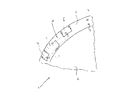
Figure 1 shows a schematic representation of a plan view

CA 02216470 1997-09-24
of a section of a lid with the peripheral channel;
Figure 2 shows a schematic representation of the lid of
Figure 1 through A-A;
Figure 3 shows a schematic representation of a cross-
section of the lid of Figure 1 through B-B;
Figure 4 shows a schematic representation of a cross-
section of the lid of Figure 1 through C-C;
Figure 5 shows a schematic representation of an alternate
embodiment of the cross-section of Figure 4; and
lo Figure 6 shows a schematic representation of a cross-
section of a channel of a lid.
Referring to Figure 1, a lid 1 is shown with a
central section 2 and a channel 3. Central section 2
would normally be substantially planar, but may have any
convenient surface. In addition, central section 2 would
have a pour spout or other opening for discharge of
contents of the container, not shown. The pour spout
would be used for discharge of the contents of the
container, at which time the vent plug of the invention
would be in an open position, as discussed herein.
Channel 3 of lid 1 has a vent plug, generally
indicated by 4. Vent plug 4 is elongated, and would
normally be a generally elongated rectangular shape, as
illustrated in Figure 1. Vent plug 4 has hinge 5 at one
end of the vent plug and lever section 6 located at the
opposed end. Hinge 5 and lever section 6 are connected
by two sections of reduced tear strengths, indicated by
7, which define the side dimensions of vent plug 4. Vent
plug 4 is intended to be opened by levering at lever
section 6 and hinging about hinge 5, preferably so that
the vent plug as defined by lever section 6 and the
sections of reduced tear strength 7 may be hinged about
hinge 5 and located and retained between projections 8
and 9. Projections 8 and 9 are optional, but are
preferred. Such projections will retain vent plug 4 in an
open position, and are cooperatively located to do so.

- - -
CA 02216470 1997-09-24
Figure 2 shows hinge 5 of vent plug 4 located in
channel 3. Hinge 5 has hinge groove 10 on the upper
surface 12 of channel 3 and an opposed interior groove 11
on the interior surface 13 of channel 3. Hinge groove 10
and interior groove 11 cooperate to form hinge 5.
Figure 3 shows lever section 6. Lever section 6 has
groove 14 located in interior surface 13 of channel 3.
In upper surface 12 of channel 3, lever section 6 has
lever groove 15, which is cooperatively located with
o recess section 14 so that channel gate 16 of reduced
thickness is formed in channel 3. Figure 3 shows that
lever section 15 has pivot point 17 extending upwards
from upper surface 12 on one side of lever groove 15 and
lever mount 18 on the opposed side of lever groove 15.
Figure 4 shows the cross-section of vent plug 4 as
having plug grooves 20 and 21. Plug grooves 20 and 21
extend from lever section 6 to hinge 5, and would
normally be parallel to each other, or substantially so
to facilitate the opening of vent plug 4. Figure 4 shows
the embodiment in which plug grooves 20 and 21 are
located in the upper surface 13 of channel 3, forming
plug gates 22 and 23 respectively juxtaposed to upper
surface 12 of channel 3. Plug grooves 20 and 21 form the
sections of reduced tear strength, and hence define the
sides of vent plug 4.
Figure 5 shows the alternate embodiment in which
channel 3 has grooves on both upper surface 12 and lower
surface 13. Lower groove 25 is cooperatively located
with upper groove 26 in upper surface 12 to form vent
plug gate 29 therebetween. Similarly, lower groove 27 is
in lower surface 13 and upper groove 28 is in upper
surface 12, forming vent plug gate 30 therebetween.
Figure 6 shows a cross-section of channel 3 and, in
part, central section 2 of lid 1. Channel 3 has an
alternate lip 30 spaced from ridge 31, forming groove 32
therebetween. Groove 32 would normally have a sealing

CA 02216470 1997-09-24
compound therein e.g. a rubber gasket to effect sealing
of the pail. It is understood that the wall of the pail
would fit into sealing groove 32 to effect closure of the
pail. Channel 3 also has channel interior wall 33 spaced
from ridge 31 to form groove 34. Groove 34 would
frequently contain struts between ridge 31 and interior
wall 33 for support of lid 1 e.g. to provide rigidity to
the lid and reduce the likelihood that the lid will pop
off the pail during use, as is known. However, it is
o understood that any such struts should not be located in
the same location as vent plug 1. As illustrated in
Figure 6, the vent plug is located interior to the
location of the wall of the pail, such that when the vent
plug is in an open position there is fluid flow
communication between the interior of the pail and the
ambient air, to allow air to enter the pail during
discharge of the contents of the pail.
In operation, the pail is filled with flowable
material and the lid is placed on the pail. The pail
would then normally be shipped to another location for
use. The user would open the pouring spout, and would
lever open the vent plug to provide the vent during
pouring of flowable material from the pail. This also
provides evidence that the pail has been opened.
It is understood that other known techniques could
be used to provide evidence of tampering with the pail,
in addition to the vent plug described herein.
The vent plug may be of any convenient size with
respect to the design of the lid of the pail. However,
as an illustration of the dimensions of an embodiment of
the vent plug of the invention, the vent plug may have a
length of about one inch and a width of about 0.2 inches.
The thickness of the gates at the sections of reduced
tear strength may be about 0.01 inches. However, it will
be appreciated that the dimensions will depend on many
factors, including dimensions of the pail and the channel

-
CA 02216470 1997-09-24
on the lid, and the material of construction of the pail.
The vent plug of the present invention provides a
tamper-evident vent that is conveniently opened, and
which may be retained in an open position in order
facilitate the flow of air into the pail during discharge
of the contents of the pail. Location of the vent plug in
the raised peripheral channel of the lid reduces the
likelihood of contamination of the contents of the pail
on opening the vent plug. The location may also assist in
o the pouring of flowable material from a container,
compared to use of a vent located in the lid of a
container, as air should be located within the container
at the vent thereby facilitating immediate flow of
material from the container on discharging of the
contents of the container.

Representative Drawing
A single figure which represents the drawing illustrating the invention.
Administrative Status

2024-08-01:As part of the Next Generation Patents (NGP) transition, the Canadian Patents Database (CPD) now contains a more detailed Event History, which replicates the Event Log of our new back-office solution.

Please note that "Inactive:" events refers to events no longer in use in our new back-office solution.

For a clearer understanding of the status of the application/patent presented on this page, the site Disclaimer , as well as the definitions for Patent , Event History , Maintenance Fee  and Payment History  should be consulted.

Event History

Description Date
Inactive: IPC from MCD 2006-03-12
Application Not Reinstated by Deadline 2003-09-24
Inactive: Dead - RFE never made 2003-09-24
Deemed Abandoned - Failure to Respond to Maintenance Fee Notice 2003-09-24
Inactive: Abandon-RFE+Late fee unpaid-Correspondence sent 2002-09-24
Inactive: Correspondence - Formalities 2001-06-13
Inactive: Inventor deleted 2000-06-06
Letter Sent 1999-05-14
Inactive: Single transfer 1999-04-20
Application Published (Open to Public Inspection) 1999-03-24
Letter Sent 1999-02-24
Extension of Time for Taking Action Requirements Determined Compliant 1999-02-24
Inactive: Delete abandonment 1999-02-23
Inactive: Extension of time for transfer 1999-01-20
Inactive: Abandoned - No reply to Office letter 1999-01-20
Inactive: Transfer information requested 1998-10-20
Inactive: Correspondence - Transfer 1998-10-05
Inactive: Single transfer 1998-08-10
Inactive: IPC assigned 1997-12-22
Classification Modified 1997-12-22
Inactive: First IPC assigned 1997-12-22
Inactive: IPC assigned 1997-12-22
Inactive: Courtesy letter - Evidence 1997-12-02
Inactive: Filing certificate - No RFE (English) 1997-12-01
Filing Requirements Determined Compliant 1997-12-01
Application Received - Regular National 1997-11-28

Abandonment History

Abandonment Date Reason Reinstatement Date
2003-09-24

Maintenance Fee

The last payment was received on 2002-09-10

Note : If the full payment has not been received on or before the date indicated, a further fee may be required which may be one of the following

  • the reinstatement fee;
  • the late payment fee; or
  • additional fee to reverse deemed expiry.

Please refer to the CIPO Patent Fees web page to see all current fee amounts.

Fee History

Fee Type Anniversary Year Due Date Paid Date
Registration of a document 1997-09-24
Application fee - standard 1997-09-24
Extension of time 1999-01-20
MF (application, 2nd anniv.) - standard 02 1999-09-24 1999-09-22
MF (application, 3rd anniv.) - standard 03 2000-09-25 2000-09-21
MF (application, 4th anniv.) - standard 04 2001-09-24 2001-09-24
MF (application, 5th anniv.) - standard 05 2002-09-24 2002-09-10
Owners on Record

Note: Records showing the ownership history in alphabetical order.

Current Owners on Record
INDUSTRIAL CONTAINERS LTD.
Past Owners on Record
PETER J. LOVELL
STEPHEN H. ARSHINOFF
Past Owners that do not appear in the "Owners on Record" listing will appear in other documentation within the application.
Documents

To view selected files, please enter reCAPTCHA code :


To view images, click a link in the Document Description column. To download the documents, select one or more checkboxes in the first column and then click the "Download Selected in PDF format (Zip Archive)" or the "Download Selected as Single PDF" button.

List of published and non-published patent-specific documents on the CPD .

If you have any difficulty accessing content, you can call the Client Service Centre at 1-866-997-1936 or send them an e-mail at CIPO Client Service Centre.


Document
Description 
Date
(yyyy-mm-dd) 
Number of pages   Size of Image (KB) 
Representative drawing 1999-04-12 1 4
Cover Page 1999-04-12 1 35
Description 1997-09-24 6 249
Claims 1997-09-24 1 31
Drawings 1997-09-24 3 36
Abstract 1997-09-24 1 14
Filing Certificate (English) 1997-12-01 1 164
Request for evidence or missing transfer 1998-09-28 1 110
Reminder of maintenance fee due 1999-05-26 1 112
Courtesy - Certificate of registration (related document(s)) 1999-05-14 1 116
Reminder - Request for Examination 2002-05-27 1 118
Courtesy - Abandonment Letter (Request for Examination) 2002-12-03 1 167
Courtesy - Abandonment Letter (Maintenance Fee) 2003-11-19 1 176
Correspondence 1997-12-02 1 31
Correspondence 1998-10-20 1 10
Correspondence 1999-01-20 2 89
Correspondence 1999-02-24 1 8
Correspondence 2001-06-13 1 28
Fees 1999-09-22 1 50
Fees 2002-09-10 1 51
Fees 2001-09-24 1 50
Fees 2000-09-21 1 49