Note: Descriptions are shown in the official language in which they were submitted.
CA 02216646 1997-09-26
W 096/30064 PCT~US9~10~361
--1--
Description
Multiple Hole Druq Delivery Balloon
Technical Field
This invention generally relates to balloon catheters
~or forcibly expanding a coronary artery and for
dispensing medications. More particularly this invention
is directed to a balloon catheter capable o~ delivering
medications and to a method of manufacturing such a
balloon catheter.
10 Backqround Art
Balloon catheters for expanding atherosclerotic
lesions or stenosises are well known in the heart. Such
devices include inflatable balloons disposed at the end of
multi-lumen catheter shafts. A pressurizing fluid forced
into the balloon through an in~lation lumen expands the
balloon into the surface of an artery to enlarge its cross
section.
United States Letters Patent No. 4,994,033 to Shockey
et al. discloses a variation on a balloon catheter that is
designed to apply a liquid medicament or other substance
to a stenotic lesion as the blood vessel is undergoing
dilatation to facilitate the restoration and long-term
maintenance of patency to the blood vessel. This
particular catheter includes three concentrically arranged
flexible plastic tubes and a pair o~ concentrically
arranged expansion members located at the distal end of
the tubes. The space between the outer wall of the inner
tube and the inner wall of the intermediate tube is in
~luid communication with the interior o~ the first
expander member. The second space between the outer wall
of the intermediate tube and the inner wall o~ the outer
tube is in fluid communication with the interior of the
second expander member. A plurality of minute holes are
formed through the second expander member to permit the
liquid medicament to be ejected from the second expander
member while an inflation fluid is introduced into the
lumen of the intermediate tube.
CA 022l6646 l997-09-26
W 096/30064 PCTrUS~/0~61
--2--
Essentially, the Shockey et al. patent discloses two
concentric balloons with an annular chamber formed between
the balloons for receiving a medication that then
disperses through the outer balloon through a series of
5 holes. Other devices for performing these functions also
exist. For example, Unites States Letter Patent No.
~ 5,207,644 to Strecker discloses a similar device in the
form of an implantable infusion chamber; and United States
Letters Patent No. 5,320,604 to Walker et al. discloses a
10 pair of expander balloons spaced apart on opposite sides
of a waist portion at the distal end of a catheter in
which the waist portion includes an infusion section with
a perforation in communication with a drug delivery lumen.
United States Letters Patent No. 4,693,243 to Buras
discloses a flexible, non-collapsible conduit system for
directly ;~t~m;ni stering topical anesthesia in which the
conduit system is separately positioned about a cuffed
endotracheal tube for a direct topical application of
additional substances to tissues of the larynx. United
States Letters Patent No. 5,295,962 to Crocker et al.
discloses a drug delivery and dilatation catheter that
includes a inflation balloon disposed about a catheter and
a perforated drug delivery balloon disposed concentrically
about the inflation balloon. The drug delivery balloon
contains a plurality of delivery ports over some or all of
the surface of the delivery balloon or alternatively
comprises a permeable material. United States Letters
Patent No. 5,049,132 to Shaffer et al. also discloses a
balloon catheter with concentric balloons. In this patent
the outer balloon has apertures or slits that permit
liquid flow outwardly through the balloon.
Increasing the pressure applied at the proximal end
of many of the foregoing balloon catheters for
administering a medicant increases the flow rate through
the apertures . With sufficient pressure, "jetting~
occurs whereby a relatively high-velocity stream emerges
from the balloon with enough momentum to damage
surrounding tissue. As one solution to this problem
CA 02216646 1997-09-26
~096/30064 PCTrUS9f'n~61
United States Letters Patent No. 5,213,576 to Abiuso et
al. discloses two concentric balloons in which a
medicament is directed into a central balloon and escapes
through apertures in the inner balloon that are o~set
from apertures in an outer balloon. Each of the apertures
or ports is sized to permit medication delivered through
the lumen to pass outwardly through the perforations o~
both balloons, but the offset nature of the apertures
prevents jetting.
United States Letters Patent No. 5,318,531 to Leone
discloses an alternative infusion balloon catheter in
which a balloon carries a plurality of holes sized to
permit medication to be delivered through a lumen to pass
outwardly through the holes. The balloon also carries on
15 an outer sur~ace a substantially hydrophilic, tubular,
microporous membrane that covers the holes to break up
streams of ~lowing medication.
More recently, an alternative balloon catheter,
called a channel balloon, has been developed ~or the
treatment o~ vascular disease including the delivery o~
medication to a site. One embodiment o~ such a balloon is
shown in United States Letters Patent No. 5,254,089 to
Wang. This channel balloon comprises a hollow,
in~latable, extruded medication delivery balloon at the
25 distal end o~ the catheter. Like other balloons, the
interior o~ the channel balloon is in ~luid ~low
relationship with one o~ several catheter lumens to enable
the balloon to be in~lated. In this particular structure,
however, the balloon has inner and outer walls and
30 angularly spaced radial webs that de~ine an array o~
longitudinally extending conduits between the walls o~ the
balloon. Another lumen in the catheter shaft delivers
medication to these conduits, and the walls o~ the balloon
have a single aperture ~or allowing the release o~ the
35 medication ~rom each conduit.
In the particular embodiment shown in the Wang
patent, each conduit has a single port ~ormed by in~lating
both the balloon and the conduits with air and then
CA 02216646 1997-09-26
W 096130064 PCTrUS96/04361
pricking each conduit wall lightly with a pin until it
deflates. It is also suggested that the conduits could be
pierced with laser irradiation. Apertures in the range
from 0.0025 mm to 2.5 mm are suggested as potential
5 aperture sizes depending upon the viscosity of the
medication being dispensed. Elongated slits and other
alternative aperture shapes are suggested.
As the medicament being administered moves directly
through the exterior wall from an individual conduit in
10 this channel balloon, jetting from the single apertures
can still occur. Moreover, forming apertures in the outer
wall is more complicated in a channel balloon that it is
in a concentric balloon structure. For example, with
individual concentric balloons it is possible to laser
15 drill holes through one balloon as an outer balloon while
it is separated from the final catheter assembly and then
to overlay the outer balloon on the inner balloon. With
conventional laser drilling, the laser is energized for an
interval that assures complete penetration of the material
20 being drilled. In a channel balloon, however, that
approach to laser drilling would require sophisticated
controls designed to produce just sufficient energy during
a single application of laser energy to drill the exterior
wall without significantly penetrating or weakening of the
inner wall. Otherwise the structural integrity of the
entire channel balloon can be compromised. Instead, these
single ports are formed by incremental pulsing of a laser
beam so it removes only a portion of the exterior wall.
As each laser pulse interacts with the exterior wall,
reflections at the walls tend to produce uneven energy
distributions across the hole being drilled. This process
can form tabs of material that are weakly connected to the
rh~nn~l balloon. There is always a potential for such
material to release and ~orm debris that can block the
channel or, in the worst case, exit with the medication
into the patient. These and other criteria would require
the implementation o~ complicated and unduly expensive
CA 022l6646 l997-09-26
W~ /3C C1 PCT/U~G~a~?Cl
manu~acturing controls to adapt prior art procedures for
avoiding jetting to an extruded channel balloon.
Disclosure o~ Invention
Therefore, it is on object o~ this invention to
5 provide an improved inflatable medical device for the
intravascular delivery of medications.
Another object o~ this invention is to provide an
improved inflatable medical device that mln;mi zes jetting
ef~ects during the administration of a medication.
Still another object o~ this invention is to provide
an improved inflatable medical device for the
intravascular delivery of medication at high flow rates
without jetting ef~ects.
Yet another object of this invention is to provide an
15 improved in~latable medical device for the intravascular
delivery of medications with a channeled expansible
balloon.
Yet still another object of this invention is to
provide an improved inflatable, channeled balloon catheter
20 for the administration of medication that is readily
manu~actured.
Still yet another object of this invention is to
provide an improved, reliable and inflatable, channeled
balloon catheter medical device ~or the intravascular
25 delivery of medications.
In accordance with one aspect of this invention, a
medical device for the intravascular delivery of
medications includes an inflatable balloon having at least
one conduit that extends between interior and exterior
30 walls for substantially the entire length of the balloon.
Lumens are provided for inflating the balloon and for
7 delivering medications to the conduit. An array o~
closely spaced ports through the exterior wall are grouped
in an area that is significantly less than the area of the
35 exterior wall coextensive with the conduit thereby to
enable medication to exit the conduit.
In accordance with another aspect of this invention,
a medical device for the delivery of medications includes
CA 02216646 1997-09-26
W 096/30064 PCTrUS96~04361
a multi-lumen catheter having a distal end adapted to be
disposed within a bodily organ. A hollow, inflatable,
balloon defined by interior and exterior walls and distal
and pro~; m~ 1 ends is disposed on the distal end of the
catheter. The interior of the balloon is in fluid flow
relationship with one lumen to enable the introduction of
an inflation fluid to the interior of the balloon. A
plurality of conduits formed intermediate the interior and
exterior walls receive medications. The exterior wall of
10 each conduit has a given exterior wall area. Each conduit
is adapted to receive medications through another lumen
and includes an array of closely spaced ports through the
exterior wall. Each array covers an area that is
significantly less than the exterior wall area over the
conduit.
In accordance with another aspect of this invention
an inflatable medical device for the delivery of
medications to an organ in the body includes a hollow,
inflatable, medication-deliverable balloon defined by
interior and exterior walls. The exterior wall contains
an array of closely spaced ports constructed by
positioning an optical mask proximate the exterior wall.
The optical mask includes a plurality of apertures
therethrough that correspond to the desired array. Laser
25 pulses are directed toward the optical mask with the
energy in a single pulse limited to a level that removes
only an incremental portion of the exterior wall material.
The pulse energy is spread to illuminate all the apertures
in the mask simultaneously. The process is monitored
30 until the presence of laser energy on the inner wall is
detected whereupon the sequence of laser pulses
terminates.
Brief Description of the Drawings
The appended claims particularly point out and
35 distinctly claim the subject matter of this invention.
The various objects, advantages and novel features of this
invention will be more fully apparent from a reading of
the following detailed description in conjunction with the
CA 02216646 1997-09-26
W 0 96/30064 PCTrUS9"01~61
accompanying drawings in which like reference numerals
re~er to like parts, and in which:
FIG. 1 is a side elevational view of a medical
balloon according to the present invention shown in an
inflated configuration with a portion of balloon being cut
away to show its interior;
FIG. 2 is cross section taken along lines 2-2 in FIG.
1 showing the attachment between the catheter shaft and
the balloon;
FIG. 3 is an enlarged plan view o~ a portion o~ the
balloon in FIG. 1 that includes one conduit and portions
o~ adjacent conduits;
FIG. 4 depicts the portion o~ the balloon shown in
FIG.3 in perspective;
FIG. 5 depicts, schematically and in block form,
apparatus use~ul in the manu~acture o~ a balloon
constructed in accordance with this invention; and
FIGS. 6A through 6D depict the formation o~ a single
aperture through an exterior wall o~ the balloon during
20 manufacture on the apparatus shown in FIG. 5.
Best Mode for Carrying Out the Invention
A balloon-type catheter 10 o~ the present invention
is similar to other catheters used for treating coronary
artery disease. As is conventional, the catheter 10
attaches to an array of hubs (not shown) being typically
made of rigid materials. These hubs enable the
introduction of inflation ~luids, medication and a guide
wire as will be described hereina~ter. The hubs attach to
the proximal end o~ a multilllm~n~l tube or catheter sha~t
12 as is conventional.
The catheter shaft 12 carries a medical balloon 14 at
its distal end. The balloon 14 comprises materials
described herein and is heat sealed or adhesively attached
(as is conventional) at its respective proximal end 16 and
35 distal end 18 to the catheter sha~t 12. A collar 20 ~its
around the proximal end 16 of the balloon 14; an optional
collar may be attached to the distal end 18. An inflation
port (not shown) provides communication between the
CA 02216646 1997-09-26
W 096/30064 PCTrUS96104361
interior of the balloon 14 and an inflation lumen 24, as
also known in the art. Lumen 24 communicates with any
desired source of inflation fluid at the hubs mentioned
above as is conventional for balloon catheters.
The medication lumen 26 extends completely through
the catheter shaft 12 and communicates with a medication
injection port 28 at the proximal end 16 of the balloon
14. The medication injection port 28 communicates with a
manifold 30 that is formed between the collar 20 and the
catheter shaft 12 and that is in fluid flow communication
with medication dispensing conduits 32.
A third lumen 34 extends completely through the
catheter shaft 12. This lumen 34 allows a conventional
guidewire 36 to be inserted through the balloon 14 to
15 assist in catheter insertion in a conventional manner.
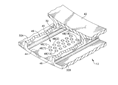
FIGS. 3 and 4 depict a portion of a balloon 14 that
forms one conduit 32 and portions of adjacent conduits 32A
and 32B and that, as shown in FIGS. 1, 3 and 4, includes
an array 40 of apertures or ports for dispensing
20 medication. Still referring to FIGS. 3 and 4, the balloon
14includes an inner cylindrical expansible wall 42 and an
outer expansible wall 44 spaced from the inner wall 42 by
radially extending webs 46.
The array 40 of apertures includes, in this specific
25 embodiment an array of eighteen ports 48(1) through 48(18)
organized in three rows centered on parallel axes 50(1),
50(2), 50(3) that parallel the webs 46. The apertures 48
additionally are arranged in offsetting columns. For
example, ports 48(1) and 48(13) are at the intersections
30 of a center line 52(1) with center lines 50(1) and 50(3),
respectively. Ports along the axis 50(2), such as port
48(7), are offset and lie on a center line 52(2) parallel
to center lines 52(1) and 52(3) and midway therebetween.
If dl represents the distance between adjacent ones of the
35 axes 50; d2, the distance between the center lines of
adjacent ports along an axis such as the distance between
center line 52(1) and 53(3); and d3, half the distance of
CA 02216646 1997-09-26
~VO~-'3~~C1 PCTrUS96/0436
_g_
d2, spacing for maintaining the integrity of the material
intermediate adjacent ports can be realized so long as
2 2d
d2 2 2d
d3 2 d
where "d" is the nominal diameter of an individual one of
the ports 48. I~ the ports 48 have a diameter of 30~m,
according to equations (1) through (3) the array 40
occupies an area of about 150~m by 330~m. In one
10 particular embodiment the distance d2 is increased over
the minimum and the array 40 has an area of 160~m by 450~m
whereby the m; n~ mllm spacing between adjacent ports in any
direction is equal to or greater than the port diameter,
d.
The production of a balloon 14 as shown in FIGS. 3
and 4 with an array 40 can be accomplished with the
specifically disclose,d pattern shown in FIGS. 3 and 4 or
with any alternate configuration. The number of ports 48
can be varied. In accordance with certain objectives o~
this invention, however, in whatever form, this structure
allows medication transmitted throughout the conduit 32 to
ooze from the ports 48 collectively. Given the close
proximity of the apertures 48 and their small sizes, the
individual ports seem to act more like capillaries than
25 nozzles, so the medication streams or jets observable in
the prior art do not appear. This jetting is overcome
without adding materials to the balloon or constructing a
balloon with inner and outer ports that necessitates the
use of an inflation fluid, the removal of an inflation
fluid and the subsequent introduction o~ an additional
fluid for the purposes of inflating the balloon and
therea~ter ~m; n; stering the medicine, with its obvious
complexity and disadvantages.
FIG. 5 schematically depicts manufacturing apparatus
60 that is useful in ~orming the array 40. In one
particular embodiment, an excimer laser 62 and
conventional laser optics 64 form a laser beam having
CA 02216646 1997-09-26
W 096130064 PCTrUS9CI0~61
--10--
boundaries represented by dashed lines 66 and that covers
an area corresponding to at least the area of the array to
be formed. As previously indicated, an array generally
will cover an area less than lmm2 (i.e. less than 1000 ~m
5 on each side). With such areas optics 64 can produce a
substantially even energy distribution across the area of
the array. The methods for producing a laser pulse having
these characteristics and a sequence of such pulses is
well known in the art.
An optical mask 68 includes a plurality of apertures,
such as apertures 70(1) through 70(18), that correspond to
the array 40. After the mask 68 is interposed between the
laser optics and the exterior wall 44, laser energy from
the optics 64 strikes the mask 68, but passes through the
15 mask 68 only in the areas corresponding to the various
apertures 70 in the mask. Consequently the laser optics
~ 64 and mask 68 will illuminate the exterior wall 44 with
laser energy in the desired pattern. Dashed lines 72
depict the transfer of energy througR the aperture 70(13)
20 to the exterior wall 44.
The apparatus 60 additionally includes a pulse
control circuit 74 that establishes laser parameters of
pulse amplitude, width and repetition to enable the laser
62 to illuminate the mask 68 with a sequence of controlled
finite energy pulses. More speci~ically, it is desired to
control pulse amplitude and width so each pulse removes
only an incremental portion of the material in the
exterior wall 44. If the balloon 14 is extruded from
polyethylene terapthalate or similar material, the pulse
control circuit 74 may limit each laser pulses to an
energy of 1 millijoule, such that it requires 20 to 25
pulses penetrate the exterior wall 44.
FIGS. 6A through 6D depict the progressive removal of
one aperture through the exterior wall 44 under the
application of a series of laser pulses. FIG. 5A
represents the balloon 14 after the laser beam 72 has been
pulsed one or two times and depicts a slight depression
76A made by the removal of a first incremental portion of
CA 02216646 1997-09-26
W 096130064 PCT/U~10~61
the material of the exterior wall 44. Successive pulses
deepen the hole as shown in FIG. 6B by the depression 76B
in the exterior wall 44. A~ter a number o~ pulses, the
laser will remove all the material in the exterior wall 44
5 as shown in FIG. 6C. A next laser pulse passes through
the aperture 76C shown in FIG. 6D and strikes the interior
wall 42. In essence, the materials in the walls 42 and 44
generally are opaque or semi-opaque so an operator can
visually determine when an aperture such as aperture 76 is
~ully formed by the appearance of a surface irregularity
on the interior wall 42. At that point the operator stops
the laser pulse sequence.
Normally, the laser pulse control 74 may be as simple
as a manually activated single-pulse circuit so each pulse
is controlled individually. Alternatively, the m~nl]~l
control might initiate a short pulse train o~ 2 or more
pulses in a burst. Typically this control would be
designed so that only one or two pulses would be generated
after the hole 76C is ~ully ~ormed. These pulses may ~orm
a surface irregularity 78 on the inner wall 42. However,
the incremental material that is actually removed does not
a~ect the overall strength or integrity of the inner wall
42.
Mechanically forming apertures such as apertures 48
in FIG. 2 by pricking or otherwise can produce ~lashing
around the hole. Even a tightly focused laser beam for
drilling a single hole can produce flashing around the
peripheral edges because there can be a significant
variation in energy distribution across the diameter of
the hole. Such ~lashing is dif~icult to remove,
particularly in a channel balloon, and it is possible for
such flashing to detach during use. The laser optics 64
in FIG. 5 spreads the resulting laser beam over the array
and assures a relatively constant energy distribution
35 across portions o~ the beam passing through the optical
mask 68 that is in a single laser beam represented by the
dashed line 72. As the energy in each beam from the mask
68 will be substantially constant, each hole 48 tends to
CA 022l6646 l997-09-26
W O9~3___1 PCT~US96/01361
-12-
form at equal rates through the exterior wall 46 so that
within one or two pulses all the holes will be bored at
the same time. This ml n;ml zes any damage by laser energy
impacting the interior wall 42.
Moreover, as compared with the prior art, the
combination of the use of the mask to form an array of
small holes, rather than a single hole also minimizes the
size of any tabs or flash that remain after ~orming the
holes. Whereas such tabs or flashing in prior art
sufficiently large to produce problems if they were to
migrate into a patient, with the process of this invention
any flashing or tabs that might be produced are of
negligible size and quantity.
As will now be appreciated, conventional laser
drilling is not adapted for producing an array in a
channel balloon. Laser pulse width and amplitude are
selected to form a port with one pulse. Any variation in
the energy from port to port could produce an array with
fully formed and partially formed apertures. A successive
pulse, without other controls, would pass through any
fully formed holes and damage the interior wall. The use
of differential or incremental energy pulses in accordance
with this invention overcomes this problem because the
energy applied at a location in the array during each
pulse is substantially constant and because the energy in
any one pulse is insufficient to penetrate fully the
exterior or interior wall.
Thus a balloon catheter structured in accordance with
this invention meets the several objectives of this
invention. Specifically, the apparatus and method of
operation as shown and described with respect to FIGS. 5
and 6A through 6D provide reliable and straightforward
balloon production with controlled aperture arrays in the
exterior walls of each conduit in a channel balloon. The
process is readily adapted for forming multiple arrays,
although individual arrays in any given conduit will be
separated. Moreover, each array will have an overall area
that is insignificant with respect to the total area of
CA 02216646 1997-09-26
VVO 96/30064 PCTrUSr~'~q~61
the exterior wall portion corresponding to a given
conduit. Finally, the array of closely spaced holes
m;n;m; zes jetting encountered in prior art medication
delivering balloons without the requirement o~ additional
structures or special materials.
This invention has been disclosed in terms of certain
embodiments. It will be apparent that many modi~ications
can be made to the disclosed apparatus without departing
~rom the-invention. For example, an array can take any
shape and spacing provided the spacing between adjacent
ports is suf~icient to maintain the integrity of the
exterior wall between those ports. Typically that
requires a spacing by the diameter of the aperture or
greater. Likewise the number of holes can be varied in
the array. Moreover, arrays can be ~ormed in the exterior
walls of all the conduits or in only selected ones of the
conduits. The process can also be used to ~orm apertures
in balloons of a conventional concentric form as well as
channel balloons. Therefore, it is the intent of the
20 appended claims to cover all such variations and
modifications as come within the true spirit and scope o~
this invention.