Note: Descriptions are shown in the official language in which they were submitted.
CA 02216916 1997-09-29
W O96/30619 PCT~N096/000'51
PRESSURE COhv~Kl~K (B)
This invention relates to an improved design of a
pressure amplifier or pressure converter for mounting above
the drill bit at the lower end of a drill pipe for deep
drilling, in particular for oil and gas, and for generating
an increased fluid pressure by utilizing energy in a
drilling fluid flow downwards through the drill string and
the drill pipe. This can be done for the purpose of
obtaining an enhanced drilling effect, preferably by me!ans
of one or more high pressure jets adapted to have a cutting
effect in a surrounding rock formation.
The invention can be considered as a further
development and improvement of structures described in
Norwegian patent specifications Nos. 169.088, 171.322,
171.323 and 171.32S. It has now been found that these and
other known pressure converters advantageously can be
replaced by or modified into new and improved designs t:o be
described in the following description. These new designs
involve among other things, an improved reliability and a
reduced wear and tear of important parts of the pressure
converters.
Like the pressure converters according to the above
Norwegian patent specifications, the present invention as a
starting point takes an embo~i ?nt comprising a
reciprocating piston which is moveable under the influence
of drilling fluid pressure, between opposite end positions
in a cylinder. At one side the piston has a relatively large
piston area which during piston movement in a first
direction is influenced by the drilling fluid pressure in
the drill pipe, and an oppositely facing, relatively small
piston area, which during piston movement in the first
direction generates an increased pressure in a smaller
portion of the drilling fluid flow. Valve means control the
movement of the piston in the cylinder, and conduits are
provided to r ~lln;cate with drilling fluid flow passages
within the drill pipe and the annulus outside the drill
pipe, where the drilling fluid has a relatively low
CA 02216916 1997-09-29
W O96/30619 PCT~N096/00051
pressure. A high pressure conduit with a check valve
connects the space in front of the small piston area to a
header conduit for drilling fluid at the increased pressure.
What is novel and specific to the pressure converter
according to the invention in the first place consists
therein that the space in front of the small piston area is
adapted to receive a particular working fluid and that there
is provided a moveable membrane for separating between the
working fluid and the drilling fluid.
The novel structural solutions according to the
invention as well as additional advantages and particular
features thereof, shall be explained more closely in the
following description with reference to the drawings, where:
Fig. 1 in longitudinal section shows a first embodiment
of a pressure converter according to the
invention, with the piston in an upper end
position, and
Fig. 2 in longitudinal section shows another embodiment
of the pressure converter according to the
invention, with the piston in an upper end
position.
Since the present pressure converter as far as the main
features thereof are concerned, is closely related to
corresponding structures according to the Norwegian patent
specificatio~s referred to above, it seems sufficient here
only briefly to discuss these main features and functions.
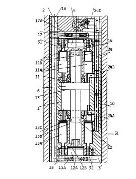
As in the previously proposed structures the embodiment
of Fig. 1 comprises as substantially cylindrical housing 1,
2, 3 adapted to enclose a piston 6. This has several active
piston areas here, i.e. in the first place an upper
relatively large piston area 11, a second and opposite large
piston area 13 and an opposite, relatively small piston area
12 at the lower end of piston member 6. This is adapted to
be freely moveable axially under the influence of varying
drilling fluid pressures at the respective piston areas.
The space or volume in front of piston area 11 can be
designated low pressure space, whereas the volume in front
of piston area 12 correspondingly can be designated high
CA 02216916 1997-09-29
W O96/30619 PCTAN096/OOO'jl
pressure space. q~his latter space is connected through a
conduit 15 with a check valve 15A, to a header conduit 16
for the resulting drilling fluid flow at an increased
pressure. Conduit 16 runs through the whole longitudinal
direction of the housing, i.e. the cylinder wall 1, for the
purpose of interconnecting several of these pressure
converter unit to a group in the same manner as in the
Norwegian patent specifications mentioned above.
In addition to the main part of piston 6 with the two
relatively large piston areas 11 and 13 as well as the high
pressure piston 12, the . ho~i ?nt of Fig. 1 has an
extension upwards ending at a second, relatively small
piston area 14 which is facing oppositely in relation to
said first small piston area 12. During piston movement
upwards caused by piston area 13 upon application of
drilling fluid from the drill pipe against it, there is
accor~ingly delivered drilling fluid at an increased
pressure through a second high pressure conduit 25 with an
associated check valve 25A leading forward to the header
conduit 16 mentioned above. Thus the pressure converter will
have a working stroke both upwardly and downwardly, so that
a return str~ke without an actual pressure increasing effect
as in the previously known designs referred to above, does
not occur here.
In order to control the drilling fluid into and out of
the cylinder for driving the piston 6 upwards and down~!ards
as explained above, the embodiment of Fig. 1 shows val~e
means adapted to be influenced by the large piston areas 11
and 13 at the respective end positions of the piston. q'he
valve means comprises a valve or slide rod 24 being
displaceable in an associated bore parallel to the cylinder
axis. On the rod 24 there are attached brackets 24A and 24B
having such an angular shape and extension that end portions
D of these brackets can project into the cylinder and be
influenced by piston areas ll and 13 in the respective end
positions of piston 6. q'hus in the position illustrated in
fig. 1 piston area ll has pushed bracket 24B and thereby rod
24 upwards to an upper position, whereas the lower brao~ket
CA 02216916 1997-09-29
W 096/30619 PCT~096/OOOSl
24A has its end portion projecting into the space in front
of piston area 13. When piston 6 approaches its lower end
position bracket 24A therefore will provide for movement of
rod 24 and in turn a rotary valve 4 being provided in the
upper end member 2 of the cylinder. The valve 4 is rotated
between two angular positions by means of a transvers arm
24C at the upper end of slide rod 24. The rotary valve 4
serves to control drilling fluid flows from the interior of
the drill pipe 10 for pressure actuation of piston 6, and
outflow of drilling fluid to annulus 50 respectively, so
that the desired reciprocating movement of piston 6 is
obtained. The above previous patent specifications show
various designs of such control valves, and it does not seem
necessary here to describe valve 4 more in detail.
At this point reference is also made to the
simultaneous international patent application directed to a
pressure converter (our ref: INT6016L) filed on behalf of
the same applicant, where the aatual piston arrangement in
the cylinder and certain other features rather closely
correspond to what is discussed above with reference to
figure 1.
What is the main point in the present invention is that
there is provided a moveable membrane, possibly several
membranes, for separating between the drilling fluid and a
particular working fluid being received in cylinder 1,2,3,
so that only this working fluid is in contact with vital
parts of the ?ch~nism, i.e. primarily the piston 6 with its
various piston areas. Such a moveable membrane is provided
at least in a chamber 12A and 14A respectively,
communicating with the space in front of piston areas 12 and
14 respectively, viz. on the high pressure side of piston 6.
More particularly from figure 1 it appears that the membrane
14B in Çh~ h~ 14A is urged up to an upper end position
whereby drilling fluid under high pressure is pressed out
through the high pressure valve 17A and the high pressure
conduit 17 to the header conduit 16. In a corresponding way
the membrane 12B in the lower chamber 12A has been brought
into an upper position under the influence of drilling fluid
CA 02216916 1997-09-29
W O96/30619 PCTAN03~ C51
pressure at the underside, ready for a return stroke in
downward direction upon successive piston movement
downwards, so that piston area 12 will press working fluid
in the space in front of this piston area downwards against
membrane 12B which will thereby be moved downwards and at
its underside further urge drilling fluid to pass through
high pressure valve 15A.
Membranes 12B and 14B as just described, are shown in
this embodiment as so-called roller membranes, these being
lo components ~nown per se from other types of equipment and
structures. Moveable membranes in the pressure converter in
figure 1 has particular interest at the high pressure side,
where roller membranes 12B and 14B are provided in spaces in
front of the small piston areas 12 and 14.
In addition to membranes 12b and 14B figure 1 also
shows roller membranes llB and 13B arranged in respective
annular chambers llA and 13A communicating with spaces in
front of the large piston areas 11 and 13 respectively, on
piston 6. At the other side these annular chambers llA and
13A communicate through conduits 31 and 32 with valve 4 so
that this can alternately apply pressure at the upper side
and underside of main piston 6 for the previously described
reciprocating movement. In a corresponding way as roller
membranes 12B and 14B, the further roller membranes llE and
2S 13B thus separate between drilling fluid flowing through
conduits 31 and 32 at the one side, and said working fluid
at the other side, i.e. that side which communicates
directly with the space in front of the large piston areas
11 and 13.
As shown specifically for roller membrane 13B this; can
be provided with a stiffening ring or plate 13C at its
central part, for in a manner known per se to contribut:e to
a desired and more secure rolling movement of the membrane
between its two end positions.
With the special shape of piston 6, comprising the
extensions upwards and downwards respectively, for the high
pressure piston areas 14 and 12, it is convenient with the
location of membrane chambers llA and 13A as shown, i.e.
CA 02216916 1997-09-29
W O96/30619 PCT~N096/00051
radially outward of each associated space in front of these
piston areas 12 and 14. As will be seen from the drawing
these are located centrally and axially in the cylinder-
piston structure.
In this embodiment membrane chambers llA and 13A are
annular, with a corresponding configuration of the
associated roller membranes llB and 13B, but it is obvious
that a number of cylindrical and separate membrane chambers
could replace each such annular chamber.
It is most practical to locate the chA~h~s 12A and 14A
for roller membranes 12B and 14B at the high pressure side,
axially outwards from each of the small piston areas 12 and
14. Then there is obtained a direct and advantageous
connection to the respective high pressure valves lSA and
17A with high pressure conduits 15 and 17.
Typically as a working fluid there will be employed a
hydraulic liquid of a suitable and commercially available
type. When the vital parts of the mech~nism, in particular
piston 6 and the various glide and piston surfaces, operate
in such a clean hydraulic liquid and separate from the
drilling flu~d, a more reliable and dependable pressure
converter apparently is obtained.
Obviously the exemplary emho~ ?nt shown in figure 1
can be varied in many ways without departing from the
essential separation between working fluid and drilling
fluid. As mentioned such modifications can relate to for
example the valve 4, the arrangement and position of
membrane chambers and so forth. As a particular detail it
is mentioned here that end dampers can be provided in
association with the small high pressure piston areas 12 and
14.
A modification of particular interest is illustrated in Q
figure 2, which is substantially correspondent to the
embodiment of figure 1, except for the moveable membrane 43B
in the lower annular membrane chamber 43A. Whereas this
membrane chamber 43A in its design completely corresponds to
annular chamber 13A in figure 1, membrane 43B is not a
roller membrane as membrane 13B, but a substantially
CA 02216916 1997-09-29
W 096/30619 PCT~N096/000!;1
cylindrical membrane being adapted.to move generally
radially in chamber 43A. In the position shown in figure 2
membrane 43B to a large extent lies against the radially
inner cylinder wall in chamber 43A, corresponding to the
piston position shown, i.e. an upper position as in fig~ure
1. When the piston is moved downwards membrane 43A will be
urged radially upwards by the working fluid so as to be
engaged more or less against the outer cylinder wall of
~-h:~ h~r 43A, while drilling fluid at the outside of membrane
43 is simultaneously pressed out downwards through the
conduit or conduits 32 (see figura 1).
It is obvious that in the ~- ho~i -nt of figure 2 t:he
annular membrane chamber above the main piston could a].so be
provided with a generally cylinder-like membrane
corresponding to the membrane 43B.