Note: Descriptions are shown in the official language in which they were submitted.
- CA 022l6999 l997-09-2~
W 096/32009 PCTrUS~G~19~'
TERMITE ~AIT STATION
The present invention relates generally to the control of
termites and other social insects. In particular, the present
invention relates to the control of such insects using an apparatus
cont~ining bait impregnated with a slow acting toxicant. For a
discussion of social insects, see generally United States Patent
Number 5,152,992. That patent is incorporated by reference herein
to the extend it discusses social insects and their habits.
o In the prior art, various technigues of ~ yillg fast acting
insecticides in a structure are used to t-limin~te social insects such
as termites in the structure. For ~olimin~ting social insects in the
ground tubular instruments with a small surface area to volume
ratio were used.
It is an object of the illve.-lion to provide an apparatus and
method for ~limin~tin~ social insects such as termites in a structure.
It is another object of the invention to provide an apparatus
and method for elimin~ting social insects in the ground.
The invention provides a method and apparatus for mollnting
within or on a structure to ~limin~te social insects such as termites.
The inv~ntion uses a cellulose bait impregn~ted with a slow acting
t~ric~nt held in a tamper resistant container, which is placed within
or mounted on the structure. The tamper resistant container, m~k~c;
the container safe to use around children and still allows termite
ent~y . Another embodiment of the i.lv~:llLion provides an apparatus
with a large surface area to intercept social insects in the ground
moving in a generally horizontal direction.
Figure 1 is a perspective view of a preferred embodiment of an
inventive bait station.
Figure 2 is a sectional view of the bait station in Figure 1 along
lines 2 - 2.
Figure 3 is a perspective view of the bait station in Figure 1, in
a flipped position.
Figure 4 is an exploded view of the bait station in Figure 1.
Figure 5 is a schematic view of the bait station in Figure 1
mounted in a structure.
CA 022l6999 l997-09-2~
W 096132009 PCTrUS96/04986
Figure 6 is an exploded view of another preferred embodiment
of a bait station.
Figure 7 is an exploded view of a preferred embodiment of a
outdoor station.
Figure 8 is a schematic view of the use of the embodiment
illustrated in Figure 7.
Figure 9 is an exploded view of another preferred embodiment
of outdoor station.
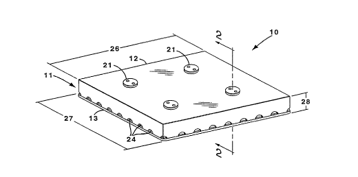
In Figures 1, 2, 3, 4 a bait station 10 has an outer cover 11,
0 comprising an opaque plastic top cover 12 and a transparent plastic
bottom cover 13. The outer cover 11, forms a flat box shape, with
the top cover 12 forming five sides of the flat box and the bottom
cover 13 forming one side of the flat box. One side of the top cover
12 and the bottom cover 13 form the sides of the flat box with the
15 greatest area. Between the top cover 12 and the bottom cover 13 is a
piece of a cardboard substrate 16 impre~n~ted with a slow acting
toxicant such as sulfluramid. In the specification and rl~im~, a slow
acting toxicant is defined as a toxicant that requIres longer than 24
hours and less than 2160 hours after ingestion of a termiticidally
20 effective amount to kill a termite. The cardboard 16 is surrounded
by the top cover 12 and the bottom cover 13. The top cover 12 is
welded to the bottom cover 13 forming the tamper resistant outer
cover 1 1.
The top cover 12 has a plurality of top cover screw holes 17.
25 The cardboard 16 has a plurality of cardboard screw holes 18, which
mate with the top cover screw holes 17. A plurality of spacers 19 are
provided, with a spacer 19 in each cardboard screw hole 18. The
bottom cover 13 has a plurality of bottom cover screw holes 20,
which mate with the cardboard screw holes 18. A plurality of screws
30 21 are provided with a screw 21 p~ ing through a top cover screw
hole 17 and its m~ting cardboard screw hole 18, and its m:~ting
bottom cover screw hole 20. As the screw 21 passes through the
cardboard screw hole 18 it also passes through a spacer 19. The
screws 21 provide a means for mounting the bait station 10 to a
35 structure. The heads of the screws 21 are specially designed to
make the bait station 10 tamper resistant.
CA 02216999 1997-09-2~
W 096/32009 PCTrUS96/04986
The bottom cover 13 has a plurality of bottom cover apertures
23 in the shape of circles. Side apertures 24 are formed at the
junction where the top cover 12 and the bottom cover 13 meet. The
bottom cover apertures 23 and the side apertures 24 are smaller
5 than the diameter of a child's finger, to prevent children from
touching the cardboard 16, thus helping to make the bait station
tamper resistant.
The outer cover 11 has a length 26. a width 27, and a
thickness 28. To provide a desirable surface area to volume ratio
0 both the length 26 and width 27 are at least five times greater than
the thickness 28 of the outer cover 11. To utilize this desirable
surface area to volume ratio, the apertures 23, 24 ~ n~l
substantially along the length and width of the outer cover 11.
In operation, an active termite tube in a structure is located.
The bait sta.ion 10 is mounted on the structure using the screws 21,
so that the ermite tube op~nings align with the side apertures 24.
Figure 5 is a schematic view of a bait station 10 mounted on a
structure 25. A termite tube 29 is located. Part of the termite tube
is broken away to allow ~lignrnent of the side apertures 24 of the bait
20 station 10 with the termite tube 29. The termites will rebuild the
termite tube into the bait station 10. Termites p~sin~ through the
termite tube pass through the side apertures to the cardboard. The
termites eat the cardboard, taking in the slow acting t-~xic~nt. The
termites go back to the colony before the slow acting toxicant kills
25 the termite, and shares the cardboard with the rest of the colony.
This provides the slow acting toxicant to the colony, thus killin~ the
whole colony. Therefore the invention provides a means for
controlling a termite colony. The controlling of a termite colony
means any of the following: the killing of the whole colony, or
30 stopping the destruction caused by the colony, or substantially
~lirnin~ting the colony.
In an alternative method of operation, if termites are under the
floor boards, a bait station 10 may be placed on the termites with the
bottom cover 13 on the bottom. Termites would then enter the bait
35 station 10 through the bottom cover apertures 23. The termites
CA 02216999 1997-09-2~
W 096/32009 PCTtUS96tO4986
again ingest the cardboard and the slow acting toxicant, taking the
toxicant back to the colony.
The transparent bottom allows the cardboard 16 to be viewed
when the bait stations are removed from the structure. Viewing the
5 cardboard 16 allows the determination of the effectiveness of the
location of the bait station 10, and whether the colony has been
eradicated, and whether the bait station 10 or the cardboard
substrate 16 needs replacing.
In Figure 6 a bait station 30 has an outer cover 31, comprising
o a tinted transparent plastic top cover 32, an opaque plastic bottom
cover 33, and an opaque side cage 34 between the top cover 32 and
bottom cover 33 and around the outer edges of the top cover 32 and
the bottom cover 33. The outer cover 31, forms a flat box shape,
with the top cover 32 forming a side of the flat box with the greatest
5 area, and the bottom cover 33 forming the other side of the flat box
with the greatest area, and the side cage 34 forming the four sides of
the flat box with the .sm~lle~t areas. Between the top cover 32 and
the bottom cover 33 and within the perimeter formed by the side
cage 34 is a piece of cardboard 36 impregn~ted with a slow acting
20 toxicant such as sulfluramid. The side cage 34 is welded to the
bottom cover 33.
The top cover 32 has a plurality of top cover screw holes 37.
The cardboard 36 has a plurality of cardboard screw holes 38, which
mate with the top cover screw holes 37. A plurality of spacers 39 are
25 provided, with a spacer 39 in each cardboard screw hole 38. The
bottom cover 33 has a plurality of bottom cover screw holes 40,
which mate with the cardboard screw holes 38. A plurality of screws
41 are provided with a screw 41 p~ c;ing through a top cover screw
hole 37 and its m~ting cardboard screw hole 38, and its m~ting
30 bottom cover screw hole 40. As the screw 41 passes through the
cardboard screw hole 38 it also passes through a spacer 39. The
screws 41 provide a means for mollntin~g the bait station 30 to a
structure. The screws 41 also secure the top cover 32 to the bottom
cover 33 so that the edges of the top cover 32 press against the side
cage 34 forming the outer cover 31 and m~king the outer cover 31
- CA 022l6999 l997-09-2
W 096132009 PCTrUS~6/019
tamper resistant. The heads of the screws 41 are square socket
heads.
The bottom cover 33 has a plurality of bottom cover apertures
43 in the shape of slots. Side apertures 44 are formed at the
5 junction where the side cage 34 and the bottom cover 33 meet. The
bottom cover apertures 43 and the side apertures 44 are small
enough to ~l~v~ t children from touching the cardboard 16, thus
helping to make the bait station 30 tamper resistant.
The operation of this bait station 30 is the same as the bait
0 station 10 above. The tinted transparent plastic top cover 32 allows
inspection of the cardboard 36 without removing the bait station 30.
Another method of operation would provide screws 41 that are
just long enough to reach from the top cover screw holes 37 to the
bottom cover screw holes 40. As the user mounts the bait station
5 30, a screw 41 is removed and replaced with a longer screw. This
allows longer screws 41 to be used only where needed for mollnting
the bait station 41.
The cardboard 16, 36 in these embodiments may be replaced
with other cellulose baits that are ingested by termites, such as
20 paper or wood. The slow acting t~ c~nt may be any tn~ric~nt that
requires more than 24 hours and less than 6 months after ingestion
of a termiticidally effective amount to kill a termite. Slow acting
toxicants useful in the present invention include, but are not limited
to: boric acid/borate, hydramethylnon, macrolide antibiotics (e.g.,
25 spinosyn A and/or D, abamectin and milbelllyci~l), insect growth
regulators such as molting disrupters or juvenile hormone
agonists/antagonists, biological agents (i.e., living org~ni.~m~ or their
reproductive stages), protozoacides, known termiticides, slow acting
poisons or mi~hlres thereof. Specific ~rnrles of molting disrupters
30 include chitin inhibitors, particularly benzoylureas such as
hexaflumuron. A preferred type of toxicant is the class of
compounds described in United States Patent Numbers 4,921,696
and 5, 177, 107. Those patents are hereby incorporated by reference.
A particularly preferred toxicant of this class is sulfluramid. Other
35 particularly preferred toxicants are abamectin, hydramethylnon,
hexaflumuron. A preferred slow acting toxicant would be a toxicant
CA 02216999 1997-09-2~
W 096/32009 PCTrUS96/04986
that requires longer than 96 hours and less than 720 hours after
ingestion of a termiticidally effective amount of toxicant to kill a
te~ ite. Other means may be used to ~tt~h the bait station to a
structure such as tape or adhesive glue. In these embodiments to
obtain a desired surface area to volume ratio, the outer container has
a length, width and thickness, wherein the length and width of the
outer container are both ~ive times greater than the thickness of the
outer container, and wherein the apertures exiend along the length
or width of the containers.
The amount of toxicant needed to control termites will vary,
depenllin~ on the particular toxicant used, but in general an amount
between about 1 and about 5,000 parts per million (ppm) of to~ic~nt
to bait will be utilized in the cellulose bait. For t-~mI~le, if
sulfluramid is the toxicant, an amount between about 10 and about
200 ppm may be used, preferably between about 50 and about 100
ppm, and if abamectin is the toxicant, an amount bet~,veen about 10
and about 200 ppm may be used, preferably between about 50 and
about 100 ppm.
In a field test, a cardboard substrate was impre~n~ted with
20 sulfluramid at 100 ppm. and placed in an outer cover with apertures.
The apertures were aligned with at least one active termite tube in a
structure and the outer cover was mounted on the structure. In 13
structures control was obtained on an average of 72 days.
In Figure 7 a outdoor station 50 has an outer box 51,
25 comprising the body 52, and a top cover 53. The outer box 51 has a
length 55, width 56, and thi~kness 57, wherein the length 55 is at
least ten times the thi(~knes~s 57, and wherein the width 56 is at least
five times the thi~kness 57. The body 52 has a plurality of apertures
60 which ~ n~i along the side of the body 52 defined by the length
30 55 and width 56 of the outer box 51. The body 52 has a plurality of
screw holes 61. The top cover 53, which extends along the length 55
and thickness 57 of the outer box 51 has a plurali~y of screw holes
65, which mate with the screw holes 61 of the body 52. A plurality of
screws 66 are provided to pass through the screw holes 65 of the top
35 cover 53 and screw into the screw holes 61 of the body 52.
CA 02216999 1997-09-2~
W 096/32009 PCTrUS96/04986
A bait holder 70 also has a box shape, and is small enough to
fit into the outer box 51. The bait holder 70 has a plurality of
apertures 72. Cellulose bait 73 impregnated with a slow acting
toxicant is placed in the bait holder 70. The bait holder 70 has a
plurality of foldable tabs 67 to allow easier removal of the bait holder
70 from the body 52. Other means may be provided to facilitate the
bait holder 70 from the body 52.
Figure 8 is a schematic illustration a plurality of the outdoor
stations in operation. Adjacent to a structure 77, there may be areas
0 that have a high~r chance of attracting termites, such as near a
water source such as a faucet 78. A U-shaped trench is made
around the area of the faucet 78 and three bodies 52 of outer boxes
51 are placed in the trenches. A bait holder 70 (Figure 7) is then
placed in each body 52 of an outer box 51. A top cover 53 is then
secured to each body 52 by the screws 66. On a peAodic basis,
possibly every three months, the screws 66 are removed, the bait
holder 70 is also removed and inspected. If the cellulose bait 73 is
intact, the bait holder 70 is put back in the body 52 and the top
cover 53 is resecured. If the cellulose bait 73 needs replacing, a new
20 bait holder 70 with new cellulose bait 73 is placed in the body 52.
The peAodic inspection allows the monitoring for termites.
As in the previous embodiments, the slow acting toxicant in
the cellulose bait 73 allows for the control of an entire colony. The
high surface area to volume ratio, due to the ratio between the length
25 55, width 56, and thi~kn~s 57 allows for a large surface area which
protects ~g~in~t termites.
In another method of operation, the outer box 51 may be laid
flat on the ground and covered with mulch.
Figure 9 is an exploded view of another outdoor station 81.
30 The outdoor station 81 has an outer box 82 with a body 83 and top
cover 84. The body 83 has a plurality of apertures 85. In this
embodiInent four bait stations 88, such as the bait station 30 shown
in Figure 6 are placed in the outer box 82 to serve as bait holders
and bait. The bait stations 88 in this embodiment are idt-ntic~l to
35 the bait stations 30 of the embodiment shown in Figure 6. The
shorter screws 41 are used for this purpose. Foldable tabs 99 made
CA 02216999 1997-09-25
W 096132009 PCTrUS96/04986
of tape are placed on the bait stations 88 to allow easy removal of the
bait stations 88. The bait stations 88 are placed so that the
apertures 89 on the bottom of the bait stations 88 face outward
towards the apertures in the body 83.
While preferred embodiments of the present invention have
been shown and described herein, it will be appreciated that various
changes and modifications may be made therein without departing
from the spirit of the invention as defined by the scope of the
appended claims.
ML:step