Note: Descriptions are shown in the official language in which they were submitted.
CA 02217013 1997-09-30
WO 961351~ PCTJ~L9~J01)189
-- 1 --
Apparatus for printing images on generally cylindrical objects.
2 FIELD OF THE INVENTION
3 The present invention relates to printing of images in
4 general and, more particularly, to devices and methods for
5 printing images on a cylindrical surface.
6 BACKGROUND OF THE INVENTION
7 Multi-color printing on cylindrical objects, such as
8 food or beverage cans, is well known.
9 In general, each can is centered on and rotates about a
10 mandrel during the printing process. Afterwards, the can is
11 filled and sealed, usually at another site.
12 The inability of the prior art to print on filled cans
13 has several disadvantages. For example, placing the cans on
14 a mandrel increases the time and cost of manufacture. In
15 addition, customized printing is relatively expensive and
16 logistically cumbersome, since printing and filling are
17 generally carried out at different sites.
18 SUMMARY OF THE INVENTION
19 The present invention seeks to provide improved appara-
20 tus and methods for centerless multi-color printing on
21 circularly cylindrical or elliptically cylindrical objects.
22 Such objects may include images and designs and may be
23 printed on objects such as cans before or even after full or
24 partial filling with liquid, carbonated beverages or other
25 fillings either vacuum packed or with a gas filling the non-
26 li~uid filled portions of the can, or other tubular objects
27 such as bottles, pens, markers, etc. Images or designs may,
28 in accordance with one embodiment of the invention, be
29 printed directly onto elliptically cylindrical objects.
30 Using the present invention, the cylindrical objects may be
31 customized with greater ease and at lower cost than the
32 prior art.
33 -In simplified terms, cylindrical objects are brought
34 i~to rolling contact with a printing device which prints on
35 the surfaces of the objects as they roll about their own
36 axis. More specifically, in accordance with a preferred
37 embodinent of the present invention, the cylindrical objects
38 are supported by an impression guide surface and brought
CA 02217013 1997-09-30
W O96135150 2 PCT~L95/00189
1 into contact with a rotating toner image bearing surface of
2 an imaging apparatus. Since the cylindrical objects contact
3 both the impression guide surface and the toner image
4 bearing surface, rotation of the image bearing surface
5 causes the objects to roll about their own axis along the
6 toner image bearing surface.
7 The rotating image bearing surface transfers an
8 electrostatic image or design to the objects as they roll.
9 There is no need for holding the objects on a guiding
lO mandrel; the objects simply roll about their own axis and
11 are printed as they roll.
12 The objects must be aligned with and conveyed to the
13 rotating toner image bearing surface so that the images can
14 be transferred onto the surfaces of the objects in a
15 controlled manner. This is accomplished, in one embodiment
16 of the invention by using a rotating dispenser which
17 supplies the objects from to the impression guide surface.
18 The dispenser incorporates a gating system designed to hold
19 the objects and deliver them to the impression surface at
20 the correct time so that they are aligned for proper
21 transfer of images thereon from the image bearing surface.
22 Where the units being printed are short compared to the
23 width of the image bearing surface, a plurality of units may
24 be delivered, end to end, for simultaneous printing.
In a preferred embodiment of the invention, the gating
26 system comprises a series of axial member disposed about the
27 turning axis of the dispenser and may be disposed, in
28 circumferentially disposed sets, axially along the
29 dispenser. In a preferred embodiment of the invention, the
30 dispenser dispenses two objects at a time to the image
31 bearing surface for printing, the objects being spaced
32 axially of each other. The rotating image bearing surface
33 prints on the circumferential surfaces of the two objects
34 during part of one revolution of the image bearing surface.
35 The continuously turning image bearing surface then prints
36 on the circumferential surfaces of a second set of axially
37 spaced cylindrical objects during a second part of a
38 revolution. There is a sufficient gap between printing on
CA 02217013 1997-09-30
W ~96/35150 3 PCTAYL95100189
1 each set of two cylindrical objects to ensure that the
2 objects do not touch and smear each other. Thus one printing
~ cycle preferably includes one complete revolution of the
~ 4 image bearing surface and transfer of a plurality of images
5 therefrom onto a plurality of objects.
6 Alternatively, the cylindrical objects may be delivered
7 to the image bearing surface by a conveyer belt. This is
8 especially useful when printing is to be performed on
9 elliptically cylindrical objects for which both the position
10 and orientation of the objects is important at the start of
11 printing.
12 In a preferred embodiment of the invention two or more
13 sets of two cylindrical objects are printed in one
14 revolution of the image bearing surface.
A controller receives information from the image
16 bearing surface and from the dispenser regarding relative
17 rotational speeds and position of the images to be
18 transferred with respect to the position of the objects. The
19 controller adjusts the speed of conveyance and transfer of
20 the objects such that the images are precisely transferred
21 from the image bearing surface to the objects.
22 Generally, transfer from a heated image bearing surface
23 fixes the images onto the cylindrical objects. In accordance
24 with a preferred embodiment of the invention, heaters may be
25 provided before and/or after transfer of the images to aid
26 fixing the images. The heaters are preferably in direct,
27 overhead contact with the cylindrical objects as they roll.
28 Preheating must take into account whether the cans are
29 filled or empty and whether the filling material is damaged
30 by heat.
31 When printing is performed on very thin empty cans, it
32 may be necessary to insert solid or hollow mandrels into the
33 cans prior to the transfer of images thereto. In this case,
34 the mandrel may be pre-heated prior to insertion and both
35 post and pre-heating steps are preferably omitted. After
36 image transfer to the cans, the somewhat cooler mandrels are
37 removed and preferably reheated prior to reuse.
38 The present inventors have found that precoating
CA 022l70l3 l997-09-30
W O96/35150 PCTA~L95/00189
-- 4 --
1 cylindrical objects, especially metallic objects, with
2 polyvinylpiridine homopolymer or with its copolymer with
styrene provides for excellent transfer of ink with
4 substantially no aging effects. Other useful adhesion
There is therefore provided, in accordance with a
6 preferred embodiment of the invention, apparatus for
7 printing images, preferably toner or liquid toner images, on
8 generally cylindrical objects, comprising:
9 an image bearing surface having an image thereon; and
an impression guide which is generally parallel to and
11 spaced from the image bearing surface, which guide supports
12 said cylindrical objects in rolling contact with said image
13 bearing surface, whereby images are transferred from said
14 image bearing surface to surfaces of said cylindrical
15 objects in contact therewith.
16 In a preferred embodiment of the invention, the
17 apparatus comprises an object dispenser which conveys said
18 cylindrical objects to said impression guide surface in
19 timed relation with said image on said image bearing
20 surface. Preferably, the object dispenser comprises a
21 plurality of axially directed gates spaced circumferentially
22 about an axis of said dispenser, wherein rotation of said
23 dispenser about said dispenser axis ~on~eys said cylindrical
24 objects onto said impression guide surface. Preferably the
25 apparatus comprises a plurality of object dispensers spaced
26 axially along said dispenser axis.
27 In preferred embodiments of the invention the apparatus
28 comprises a heater which heats heating said cylindrical
29 objects before printing and/or a fixing heater which heats
30 the objects after printing. Preferably, the heater
31 comprises:
32 a hot plate; and
33 a moving surface situated beneath and spaced from the
34 hot plate by at a distance such that an object situated
35 between the hot plate and the moving surface contacts both
36 the hot plate and the moving surface.
37 In one preferred embodiment of the invention the
38 cylindrical object is a generally circularly cylindrical
CA 02217013 1997-09-30
W O96/~SlS0 PCT~L9S/001~'9
-- 5
1 object. In another it is a generally elliptically
2 cylindrical object. As used herein elliptically cylindrical
3 is used to include non-circularly cylindrical objects which
~4 may not be mathematical ellipses but which generally
5 correspond to flattened circular cylinders.
P6 In one preferred embodiment of the invention the
7 impression guide comprises a substantially fixed, preferably
8 elastomer coated, surface along which the cylindrical objec:t
9 is guided. In another it comprises a tensioned flexible
10 surface along which the cylindrical surface is guided.
11 There is further provided fixing apparatus for fixing
12 toner images, preferably, liquid toner images, on
13 cylindrical objects such as cans partially filed with a
14 liquid, the fixing apparatus comprising:
15 a hot plate; and
16 a moving surface situated beneath and spaced from the
17 hot plate by at a distance such that an object situated
18 between the hot plate and the moving surface contacts bot:h
19 the hot plate and the moving surface.
20 There is further provided a method for printing images,
21 preferably toner images or liquid toner images, on general]y
22 cylindrical objects, comprising:
23 conveying said cylindrical objects to an image bearing
24 surface in timed relation with images on the image bearing
25 surface;
26 supporting said cylindrical objects in rolling contact
27 with said image bearing surface; and
28 transferring said images from said image bearing
29 surface to surfaces of said cylindrical objects when in
30 contact therewith.
31 In a preferred embodiment of the invention the support
32 includes supporting the cylindrical object with a support
33 which is generally parallel to the image bearing surface
34 along which the cylindrical object rolls along said suppor~.
35 In a second preferred embodiment of the invention the
36 support is a generally flexible support. In another it is a
37 generally fixed support.
38 In a preferred embodiment of the invention the
CA 02217013 1997-09-30
W O96/35150 PCT~L95100189
-- 6
1 cylindrical objects are heated before and/or after printing.
2 Preferably the cylindrical objects are precoated with a
3 polyvinylpiridine homopolymer or a polyvinylpiridine
4 copolymer with styrene prior to printing thereon.
There is further provided, in accordance with a
6 preferred embodiment of the invention, a method or printing
7 toner images, preferably, li~uid toner images on a metal
8 surface including:
9 coating the metal surface with a polyvinylpiridine
10 homopolymer or with a polyvinylpiridine copolymer with
11 styrene; and
12 printing the toner image on the coating.
13
14
16
17
18
19
21
22
23
24
26
27
28
29
31
32
33
34
36
37
38
CA 02217013 1997-09-30
W O 96/35150 PCT~L95~001~9 -- 7
1 BRIEF DESCRIPTION OF THE DRAWINGS
2 The present invention will be understood and
3 appreciated more fully from the following detailed
4 description, taken in conjunction with the drawings in
5 which:
6 Fig. 1 is a simplified sectional illustration of
7 electrostatic imaging apparatus constructed and operative in
8 accordance with a preferred embodiment of the present
9 invention;
Fig. 2 is a simplified enlarged sectional illustration
11 of the imaging apparatus of Fig. l;
12 Fig. 3 is a simplified pictorial illustration of a
13 portion of a conveyor device constructed and operative in
14 accordance with a preferred embodiment of the present
15 invention;
16 Fig. 4 is a simplified side view illustration of a
17 portion of the conveyor device of Fig. 3.
18 Fig. S is a simplified side view illustration of a
19 portion of an alternate conveyer device similar to that of
20 Fig. 3, in accordance with a preferred embodiment of the
21 invention;
22 Fig. 6 is a simplified schematic side view illustration
23 of a portion of an alternate conveyer device, suitable for
24 printing on both circularly cylindrical and elliptical]y
25 cylindrical objects, in accordance with a preferred
26 embodiment of the invention; and
27 Fig. 7 is a simplified cut of an intermediate transfer
28 member suitable for use in the apparatus of Fig. 1.
29 DETAILED DESCRIPTION OF THE PREFERRED EMBODIMENT
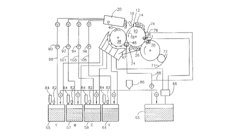
Reference is now made to Figs. 1 and 2 which illustrate
31 a multicolor printing or electrostatic imaging system,
32 constructed and operative in accordance with a preferred
33 embodiment of the present invention. As seen in Figs. 1 and
3~ 2, an imaging sheet, preferably an organic photoreceptor 1:2,
35 is mounted on a rotating drum 10. Drum 10 is rotated about
36 its axis by a motor or the like (not shown), in the
37 direction of arrow 18, past charging apparatus 1~1,
38 preferably a corotron, scorotron or roller charger or other
CA 02217013 1997-09-30
W O96/35150 PCTANL95/00189
1 suitable charging apparatus as are known in the art which is
2 adapted to charge the surface of sheet photoreceptor 12. An
3 image to be reproduced is focused by an imager 16 upon the
4 charged surface 12 at least partially discharging the
5 photoconductor in the areas struck by light, thereby forming
6 an electrostatic latent image. Thus, the latent image
7 normally includes image areas at a first electrical
8 potential and background areas at a second electrical
9 potential.
Photoreceptor sheet 12 may use any suitable
11 arrangement of layers of materials as is known in the art,
12 however, in the preferred embodiment of the photoreceptor
13 sheet, certain of the layers are removed from the ends of
14 the sheet to facilitate its mounting on drum 10.
This preferred photoreceptor sheet and preferred
16 methods of mounting it on drum 10 are described in a co-
17 pending application of Belinkov et al., IMAGING APPARATUS
18 AND PHOTORECEPTOR THEREFOR, filed September 7, 1994,
19 assigned serial number 08/301,775 and corresponding patent
20 applications filed in other countries, the disclosure of
21 which is incorporated herein by reference. Alternatively,
22 photoreceptor 12 may be deposited on drum 10 and may form a
23 continuous surface. Furthermore, photoreceptor 12 may be a
24 non-organic type photoconductor based, for example, on a
25 compound of selenium.
26 It should be noted that in other, alternative,
27 preferred embodiments of the invention, non-
28 electrophotographic methods may be used for generating the
29 electrostatic latent image. For example, the latent image
30 may be a changeable or a permanent latent image generated by
31 ionographic or other electrostatic image forming means.
32 In a preferred embodiment of the present invention,
33 imager 16 is a modulated laser beam scanning apparatus, or
34 other laser imaging apparatus, such as is known in the art.
Also associated with drum 10 and photoreceptor sheet
36 12, in the preferred embodiment of the invention, are a
37 multicolor liquid developer spray assembly 20, a developing
38 assembly 22, color specific cleaning blade assemblies 34, a
CA 02217013 1997-09-30
W 096135~50 PCT~YL95~001a9
g
1 background cleaning station 24, an electrified squeegee 26,
2 a background discharge device 28, an intermediate transfer
3 member 30, cleaning apparatus 32, and, optionally, a neu-
4 tralizing lamp assembly 36.
Developing assembly 22 preferably includes a
- 6 development roller 38. Development roller 38 is preferab]y
7 spaced from photoreceptor 12 thereby forming a gap
8 therebetween of typically 40 to 150 micrometers and is
9 charged to an electrical potential intermediate that of the
10 image and background areas of the image. Development roller
11 38 is thus operative, when maint~;ne~ at a suitable voltage,
12 to apply an electric field to aid development of the elec-
13 trostatic latent image.
14 Development roller 38 typically rotates in the same
15 sense as drum 10 as indicated by arrow 40. This rotation
16 provides for the surface of sheet 12 and development roller
17 38 to have opposite velocities at the gap between them.
18 Multlcolor li~ui~ developer spray assembly 20, who~,e
19 operation and structure is described in detail in U.',.
20 Patent 5,117,263, the disclosure of which is incorporated
21 herein by reference, may be mounted on axis 42 to allow
22 assembly 20 to be pivoted in such a manner that a spray of
23 liquid toner cont~;n;ng electrically charged pigmented toner
24 particles can be directed either onto a portion of the
25 development roller 38, a portion of the photoreceptor 12
26 or directly into a development region 44 between
27 photoreceptor 12 and development roller 38. Alternatively,
28 assembly 20 may be fixed. Preferably, the spray is directed
29 onto a portion of the development roller 38.
Color specific cleaning blade assemblies 34 are opera-
31 tively associated with development roller 38 for separate
32 removal of residual amounts of each colored toner r~m~;n;ng
33 thereon after development. Each of blade assemblies 34 is
34 selectably brought into operative association with develop-
35 ment roller 38 only when toner of a color corresponding
36 thereto is supplied to development region 44 by spray assem-
37 bly 20. The construction and operation of cleaning blade
38 assemblies is described in PCT Publication W0 90/14619 and
CA 022l70l3 l997-09-30
W O96/35150 PCT~L95/00189 -- 10 --
1 in US patent 5,289,238, the disclosures of which are incor-
2 porated herein by reference.
3 Each cleaning blade assembly 34 includes a toner
4 directing member 52 which serves to direct the toner
5 removed by the cleaning blade assemblies 34 from the devel-
6 opment roller 38 to separate collection containers 54, 56,
7 58, and 60 for each color to prevent contamination of the
8 various developers by m; ~; n~ of the colors. The different
9 color toners collected by collection containers 54, 56, 58
10 and 60 are recycled to corresponding toner reservoirs 55,
ll 57, 59 and 61. A final toner directing member 62 always
12 engages the development roller 38 and the toner collected
13 thereat is supplied into collection container 64 and there-
14 after to a carrier-liquid reservoir 65 via a separator 66
15 which is operative to separate relatively clean carrier
16 liquid from the various colored toner particles. The separa-
17 tor 66 may be typically of the type described in U.S. Patent
18 4,985,732, the disclosure of which is incorporated herein by
19 reference.
In a pre~erred embodiment of the invention, as
21 described in PCT Publication W0 92/13297, the disclosure of
22 which is incorporated herein by reference, where the imaging
23 speed is very high, a background cleaning station 24
24 typically including a reverse roller 46 and a wetting roller
25 48 is provided. Reverse roller 46 which rotates in a
26 direction indicated by arrow 50 is preferably electrically
27 biased to a potential intermediate that of the image and
28 background areas of photoconductive drum lO, but different
29 from that of the development roller 38. Reverse roller 46 is
30 preferably spaced apart from photoreceptor sheet 12 thereby
31 forming a gap therebetween which is typically 40 to 150
32 micrometers.
33 Wetting roller 48 is preferably partly immersed in a
34 fluid bath 47, which preferably contains carrier liquid
35 received from carrier liquid reservoir 65 via a conduit 88.
36 Wetting roller 48, which preferably rotates in the same
37 sense as that of drum 10 and reverse roller 46, operates to
38 wet photoreceptor sheet 12 with non-pigmented carrier liquid
CA 02217013 1997-09-30
W~ 96/35150 PCT~/00189
1 upstream of reverse roller 46. The liquid supplied by wet-
2 ting roller 48 replaces the liquid removed from drum 10 !by
3 development assembly 22, thus allowing the reverse roller 46
~ 4 to remove charged pigmented toner particles by electrophor,e-
5 sis from the background areas of the latent image. Excess
6 fluid is removed ~rom reverse roller 46 by a liquid direct-
7 ing member 70 which continuously engages reverse roller ~6
8 to collect excess liquid containing toner particles ~f
9 various colors which is in turn supplied to reservoir 65 via
10 collection cont~inPr 64 and separator 66.
11 Wetting roller 48 is preferably electrically biased to
12 a potential intermediate that of the image and background
13 areas of photoconductive drum 10, but lower than that of the
14 development roller. This biasing of wetting roller 48
15 assists in removing toner particles from the background
16 areas of photoreceptor sheet 12. Wetting roller 48 is
17 preferably spaced apart ~rom photoreceptor sheet 12 thereby
18 forming a gap therebetween which is typically 40 to Z00
19 micrometers.
Apparatus embodied in reference numerals 46, 47, 48 and
21 70 is generally not required for low speed systems, but is
22 preferably included in high speed systems.
23 Preferably, an electrically biased squeegee roller 26
24 is urged against the surface of sheet 12 and is operative to
25 remove liquid carrier from the background regions and to
26 compact the image and remove liquid carrier therefrom in the
27 image regions. Squeegee roller 26 is preferably formed of
28 resilient slightly conductive polymeric material as is well
29 known in the art, and is preferably charged to a potential
30 of several hundred to a few thousand volts with the same
31 polarity as the polarity of the charge on the toner
32 particles.
33 Discharge device 28 is operative to flood sheet 12 with
34 light which discharges the voltage remaining on sheet 12,
35 mainly to reduce electrical breakdown and improve transfer
36 of the image to intermediate transfer member 30. Operation
37 of such a device in a "write black" system is described in
38 U.S. Patent 5,280,326, the disclosure of which is
CA 02217013 1997-09-30
W O96/35150 - 12 - PCT~L95/00189
1 incorporated herein by reference.
2 Figs. 1 and 2 further show that multicolor toner spray
3 assembly 20 receives separate supplies of colored toner
4 typically ~rom four different reservoirs 55, 57, 59 and 61.
5 Figure 1 shows four different colored toner reservoirs 55,
6 57, 59 and 61 typically containing the colors Yellow,
7 Magenta, Cyan and, optionally Black, respectively. Pumps 90,
8 92, 94 and 96 may be provided along respective supply
9 conduits 98, 101, 103 and 105 for providing a desired amount
10 of pressure to feed the colored toner to multicolor spray
11 assembly 20. Alternatively, multicolor toner spray assembly
12 20, which is preferably a three level spray assembly,
13 receives supplies of colored toner from up to six different
14 reservoirs (not shown) which allows for custom colored tones
15 in addition to the standard process colors.
16 A preferred type of toner for use with the present
17 invention is that described in Example 1 of U.S. Patent
18 4,794,651, the disclosure of which is incorporated herein by
19 reference or variants thereof as are well known in the art.
20 For colored liquid developers, carbon black is replaced by
21 color pigments as is well known in the art. Other toners may
22 alternatively be employed, including liquid toners and, as
23 indicated above. Preferred liquid toners are also described
24 in the various patents and patent applications referred to
25 herein and/or incorporated herein by reference.
26 Toners that can be used with the present invention are
27 described in Example 1 of U.S. Patent 4,794,651, the
28 disclosure of which is incorporated herein by reference or
29 variants thereof as are well known in the art. For colored
30 liquid developers, carbon black is replaced by color
31 pigments as is well known in the art. Other toners may
32 alternatively be employed, including liquid toners and, as
33 indicated above, including powder toners.
34 Other toners for use in the invention can be prepared
35 using the following method:
36 1) Solubilizing 1400 grams of Nucrel 925 (ethylene
37 copolymer by Dupont) and 1400 g of Isopar L (Exxon) are
38 thoroughly mixed in an oil heated Ross Double Planetary
CA 02217013 1997-09-30
W 096/35150 - 13 - PCT~NL95/~01.~9
1 Mixer at least 24 RPM for 1.5 hours, with the o:il
2 temperature at 130~ C. 1200 g of preheated Isopar L is added
3 and m; xi ng is continued for an additional hour. The mixture
~ 4 is cooled to 45~ C, while stirring is continued over a
5 period of several hours, to form a viscous material.
6 2) Milling and Gr; n~; ng 762 grams of the result of the
7 Solubilizing step are ground in a lS attritor (Union Process
8 Inc. Akron Ohio), charged with 3/16" carbon steel balls ~t
9 250 RPM, together with 66.7 grams of Mogul L carbon blaçk
10 (Cabot), 6.7 grams of BT 583D (blue pigment produced by
11 Cookson), 5 grams o~ aluminum stearate (Riedel Dehaen) and
12 an additional 1459.6 grams of Isopar L for eight hours ,at
13 30~ C.
14 3) Continuation of Grinding In one embodiment of the
15 invention an additional grinding step is performed. In this
16 step 34.5 grams of ACumist A-12 (a micronised polyethylene
17 wax produced by Allied Signal) is added after step 2 and
18 grinding is continued for an additional 4 hours. The
19 resulting particles are fibrous particles have a measured
20 diameter in the range of 1-3 micrometers.
21 The resulting material is diluted with additional
22 Isopar L and Marcol 82 to give a working developer in which
23 the dry solids portion is about 1.7~ and in which the
24 overall ratio of Isopar L to Marcol is between about 50:1
25 and 500:1, more preferably between about 100:1 and 200:1.
26 Charge director as described in US patent application
27 07/915,291 (utilizing lecithin, BBP and ICIG3300B) and in W0
28 94/02887, in an amount approximately e~ual to 40 mg/gm of
29 solids in the final dispersion, is added to charge the toner
30 particles. Other charge directors and additional additives
31 as are known in the art may also be used.
32 The above described process produces a black toner.
33 Cyan, magenta and yellow toners can be produced by using- a
34 different mix of materials for step 2). For Cyan toner, 822g
35 of the solubilized material, 21.33 grams each of BT 583D and
36 BT 788D pigments (Cookson), 1.73 grams of D1355DD pigment
37 (BASF), 7.59 grams of aluminum stearate and 1426 grams of
38 Isopar L are used in step 2. For Magenta toner, 810 grams of
CA 02217013 1997-09-30
WO 96/35150 PCTA~L9~/00189
- 14 -
solubilized material, 48.3 grams of Finess Red F2B, 6.81
2 grams of aluminum stearate and 1434. 2 grams of Isopar L are
3 used in step 2. For yellow toner 810 grams of solubilized
4 material, 49.1 grams of D1355DD pigment, 6.9 grams of
5 aluminum stearate and 1423 grams of Isopar L are used in
6 step 2.
7 Intermediate transfer member (ITM) 30 may be any
8 suitable intermediate transfer member, for example, as
9 described in U.S. Patents 4, 684,238 and 4, 974,027 or in
10 PCT Publication WO 90/04216, the disclosures of which are
11 incorporated herein by reference. Alternatively, in a
12 preferred embodiment of the invention, ITM 30 has a
13 multilayered transfer portion such as those described below
14 or in U.S. Patents 5,089,856 and 5,047,808, or in U.S.
15 Patent application S.N. 08/371,117, filed January 11, 1995
16 and entitled IMAGING APPARATUS AND INTERMEDIATE TRANSFER
17 BLANKET THEREFOR, the disclosures of all of which are
18 incorporated herein by reference. In a preferred embodiment
19 of the invention a softer than normal intermediate transfer
20 member is used and is produced according to the following
21 method.
22 Fig. 7 shows a transfer portion 204 comprises a release
23 layer 209 which is outermost on the blanket when it is
24 mounted on drum 30. Underlying layer 209 is a conforming
25 layer 211 preferably of a soft elastomer, preferably of
26 polyurethane and preferably having a Shore A hardness of
27 about 40, although other hardnesses between about 30 and 60
28 are also sometimes suitable. Underlying layer 211 is a
29 conductive layer 214 which overlays a thin barrier layer
30 215. Barrier layer 215 overlays a blanket body 216
31 comprising a top layer 218, a compressible layer 220 and a
32 fabric layer 222. Underlying the fabric layer is preferably
33 an adhesive layer 226 which is in contact with the core of
34 drum 30.
1- The starting structure for blanket construction is a
36 blanket body 216 generally similar to that generally used
37 for printing blankets. One suitable body is MCC-1129-02
38 manufactured and sold by Reeves SpA, Lodi Vecchio (Milano),
CA 022l70l3 l997-09-30
W 096/35150 - 15 - PCT~YL9~0~ 9
1 Italy. Other preferred blanket bases have been described
2 previously in the parents of parents of U.S. Patent
3 application S.N. 08/371,117, which are incorporated herein
4 by reference. In a preferred embodiment of the invention,
5 body 216 comprises a fabric layer 222, preferably of woven
6 NOMEX material and having a thickness of about 2C)O
7 micrometers, a compressible layer 220, preferably comprising
8 about 400 micrometers of saturated nitrile rubber loaded
9 with carbon black to increase its thermal conductivity.
lO Layer 220 preferably contains small voids (about 40 - 60 %
ll by volume) and a top layer 218 preferably comprised of the
12 same material as the compressible layer, but without voids.
13 Layer 209 is preferably about 100 micrometers thick. The
14 blanket body is produced by manufacturing methods as are
15 generally used for the production of offset printing
16 blankets for ink offset printing.
17 Blanket body 216 is preferably sized to a relatively
18 exaGt thiGkness by abrading portlons of the surfaGe of top
19 layer 118. A preferred thickness for the finished body 116
20 is about 700 micrometers, although other thicknesses are
21 useful, depending on the geometry of the printing system :in
22 which it is used and the exact materials used in the blanket
23 body.
24 2- The fabric side of blanket body 216 is preferabiLy
25 coated with a 30 micrometer thick coating of silicone based
26 adhesive (preferably, Type D 66 manufactured by Dow Cornin(~)
27 for mounting onto the core.
28 3- Top layer 218 is preferably coated with a sub-micron
29 layer of primer before being coated with additional layers.
30 A preferred primer is Dow Corning 1205 Prime Coat. The type
31 of primer depends on the properties of the top layer and of
32 the conductive layer. Preferably, 0.3 micron of primer :is
33 coated onto a clean top layer with a No. O bar in a wire-rod
34 coating apparatus and is allowed to dry before applying t]le
35 conductive layer.
36 4- Since blanket body 216 may contain materials such ;~s
37 anti-oxidants, anti-ozonants or other additives which m~y
38 migrate through the upper layers of the blanket, for exampLe
CA 02217013 1997-09-30
W O96/3S150 PCT~NL95100189
- 16 -
1 as a gas when the blanket is heated during the imaging
2 process and/or in the presence of carrier liquid such as
3 Isopar L, barrier layer 215 is preferably coated onto top
4 layer 218 (or more exactly onto the primer). This barrier
5 layer should be substantially impervious to such materials
6 in the blanket body which may migrate and/or to the carrier
7 liquid which is used.
8 If this layer is omitted, under certain circumstances
9 the additive materials can cause deterioration of the
10 photoreceptor. In particular, it was found that the imaging
11 process may become humidity dependent.
12 In a preferred embodiment of the invention, a 4-11
13 micrometer layer of polyvinyl alcohol (88% hydrolyzed) is
14 coated onto the primer layer covering top layer 218.
Polyvinyl alcohol, 88~ hydrolyzed, having an average
16 molecular weight preferably between 85,000 and 145,000
17 (Aldrich Chemical Co. Inc., Milwaukee, WI) is dissolved in
18 water at 90~C by continuously stirring the mixture in a
19 reflux system for 30 minutes. After 30 minutes, a quantity
20 of ethanol equal to twice the quantity of water is added to
21 the solution, the resulting polyvinyl alcohol concentration
22 being preferably less than 10~. Higher concentration
23 solutions can be used; however, they give a more viscous
24 solution which is hard to spread evenly.
The solution is deposited on layer 218 of body 216
26 using a fine wire rod or knife inclined at 30-45~ to the
27 direction of movement of the knife or body. The solvent is
28 evaporated either by drying at room temperature or by
29 blowing hot air on the layer.
One or more coating passes are employed to give the
31 required thickness.
32 Too thin a layer will result in some transfer of
33 material from body 216, which has been correlated with
34 reduced transfer efficiency from the photoreceptor to the
35 intermediate transfer blanket, which is believed to be
36 caused by photoreceptor deterioration. While four
37 micrometers of material appears to be sufficient to avoid
38 leaching, a somewhat larger thickness such as 6 micrometers
CA 02217013 1997-09-30
wo 96135150 pCT~N195/001~9
-- 17 --
1 is preferably used.
2 Other barrier materials and other thicknesses may be
3 used depending on the carrier liquid used for the toner or
4 the gasses omitted by body 216. Other barrier materials may
5 require lesser or greater thickness depending on their
6 resistance to the carrier liquid or the gasses released by
7 body 216. Alternatively, if body 216 resists leaching by the
8 carrier liquid or does not contain materials which are
9 released (especially when body 216 is heated) or any anti-
10 oxidants and/or anti-ozonants, layer 215 may be omitted.
11 Polyvinyl alcohol is a thermoplastic crystalline
12 material having a melting point which is higher than the
13 temperature of the blanket during operation. Polyvinyl
14 alcohol is also believed to form a layer which is impervious
15 to gasses and to the hydrocarbon carrier li~uid used in the
16 liquid t~ner.
17 5- Conductive layer 214 is preferably formed of acrylic
18 rubber loaded with conductive carbon black. In a preferred
19 embodiment of the invention, only 2-3 micrometers of
20 conductive coating are required. The conductive layer is
21 formed by first compo~n~l;ng 300 grams of Hytemp 4051EP ( Zeon
22 Chemicals) with 6 grams of Hytemp NPC 50 and 9 grams of
23 sodium stearate in a two-roll mill for 20 minutes; and then
24 dissolving 150 grams of the compounded material in 2000
25 grams of methyl ethyl ketone ( MEK ) by stirring for 12 hours
26 at room temperature.
27 40 grams of conductive carbon black, such as, for
28 example, Printex XE2 ( Degussa) are added to the solution and
29 the mixture is ground in a 01 attritor (Union Proce~,s)
30 loaded with 3/16" steel balls. Gr;n~;ng proceeds at 10~C ior
31 4 hours after which time the material is diluted by t:he
32 addition of MEK to a concentration of 7. 5-8% solids and
33 discharyed from the grinder in the form of a conductive
34 lacquer.
The blanket (after step 3 or step 4) is overcoated w:ith
36 about 3 micrometers of the conductive lacquer (three pass,es
37 using a No. 0 rod) and allowed to dry for 5 minutes at room
3 8 temperature.
CA 02217013 1997-09-30
WO96/3S150 - 18 - PCT~n95100189
1 An additional coating of primer is added over the
2 conductive lac~uer (except for the portion which is to be
3 inserted into bar 108, as described hereinbelow) before the
4 soft elastomeric conforming layer is applied.
The resistance of the conductive layer should
6 preferably be more than about 20 kohms/square and preferably
7 less than about 50 kohm/square. This value will depend on
8 the resistivity of the layers above the conducting layer and
9 on the aspect ratio of the blanket. In general, the
10 resistance should be low enough so that the current flowing
ll on the conducting layer (to supply leakage current through
12 the overlying layers) should not cause a substantial
13 variation of voltage along the surface of the blanket. The
14 resistance of the conducting layer and, more importantly,
15 the resistance of the overlying layers control the current
16 flowing through the overlying layers. Generally speaking,
17 the conductive layer has a relatively low resistance and
18 resistivity, the conforming layer (layer 111) has a higher
19 resistivity and the overlying release layer (layer lO9) has
20 a still higher resistivity.
21 6- One kilogram of pre-filtered Fomrez-50 polyester
22 resin (Hagalil Company, Ashdod, Israel) is dehydrated and
23 degassed under vacuum at 60~C. 660 grams of the degassed
24 material is mixed with 1.4 grams of di-butyl-tin-diluarate
25 (Aldrich) and degassed at room temperature for 2 hours. 33
26 grams of the resulting material, 3.5 grams of RTV Silicone
27 118 (General Electric) and 4.0 grams of Polyurethane
28 cross-linker, DESMODUR 44V20 (Bayer) are stirred together. A
29 100 micrometer layer of the material is coated over the
30 primed conductive layer using a No. 3 wire rod with several
31 passes under clean conditions, preferably, class 100
32 conditions. The coating is cured for two hours at room
33 temperature under a clean hood to form a polyurethane layer.
34 Other methods of forming suitable conforming layers are
35 shown and described in the parents of U.S. Patent
36 application S.N. 08/371,117. Alternatively, the conductive
37 layer may be omitted and layer 218 made conductive.
38 Layer 211 which is thus formed should have a resisivity
CA 02217013 1997-09-30
WO 96/35150 PCT/NL9~fOO1~9
1 of the order of about 109 ohm-cm, good thermal stability c~t
2 the working temperature of the blanket surface, which is
3 preferably about 100~C or less.
4 The function of the conforming layer is to provide good
5 conformation of the blanket to the image forming surface
- 6 (and the image on the image forming surface) at the low
7 pressures used in transfer of the image from the image
8 forming surface to the blanket. While a thickness of 1()0
9 micrometers is preferred, other thicknesses, between ';0
10 micrometers and 300 micrometers can be used, with 75 to 1,25
11 micrometers being preferred.
12 7- 9 grams of RTV silicone 236 (Dow Corning) release
13 material and 3 grams RTV 118 (General Electric) and 0.'72
14 grams of Syl-off 297 (Dow Corning) are mixed together. A
15 wire rod (bar No. 1) coating system is used, with five c~r
16 six passes, under clean conditions to achieve an 8
17 micrometer release layer thickness. The material is cured ~t
18 140~C for two hours. The cured release material has a
19 resistivity of approximately 1014 to 1015 ohm-cm.
Member 30 is maintained at a suitable voltage and
21 temperature for electrostatic transfer of the image there-~o
22 from the toner image bearing surface of photoreceptor 12.
23 Intermediate transfer member 30 preferably transfers
24 the image onto the surfaces of generally cylindrical objec-ts
25 72, such as full or empty tin coated steel or aluminum cans"
26 which roll between member 30 and an impression guide surface
27 71, preferably by heat and pressure. Impression guide
28 surface 71 is preferably made of a compliant, non-sl:ip
29 material such as neoprene or synthetic rubber. Member 30 :is
30 preferably rotated by a motor 73, such as a servomotor or
31 the like, as shown in Fig. 3.
32 A conveyor device 100 for transporting cylindricc~l
33 objects 72 is described hereinbelow in greater detail wi-th
34 reference to Figs. 3, 4 and 5.
Cl~n; ng apparatus 32 is operative to scrub clean the
36 surface of photoreceptor 12 and preferably includes a
37 cleaning roller 74, a sprayer 76 for spraying a non pol~r
38 cleaning liquid, preferably cool and fresh carrier liqu:id
CA 02217013 1997-09-30
W O96/351S0 PCTAYL9S/00189 - 20 -
1 from reservoir 65, and a wiper blade 78 to complete the
2 cleaning of the photoconductive surface. The sprayed
3 carrier liquid assists in the scrubbing process and cools
4 the photoreceptor surface. Cleaning roller 74 which may be
5 formed of any synthetic resin known in the art for this
6 purpose is driven in the same sense as drum 10 as indicated
7 by arrow 80, such that the surface of the roller scrubs the
8 surface of the photoreceptor. Any residual charge left on
9 the surface of photoreceptor sheet 12 may be removed by
10 flooding the photoconductive surface with light from
11 optional neutralizing lamp assembly 36, which may not be
12 required in practice.
13 In accordance with a preferred embodiment of the
14 invention, after developing each image in a given color, the
15 single color image is transferred to intermediate transfer
16 member 30. Subsequent images in different colors are
17 sequentially formed on sheet 12 and electrostatically
18 transferred, in alignment with the previous images, onto
19 intermediate transfer member 30. When all of the desired
20 images have been transferred thereto, the complete multi-
21 color image is transferred from transfer member 30 to the
22 surfaces of the cylindrical objects 72, preferably by heat
23 and pressure. Impression guide surface 71 produces
24 resilient operative engagement between intermediate transfer
25 member 30 and cylindrical objects 72 when transfer of the
26 composite images to cylindrical objects 72 takes place.
27 It should be understood that the invention is not
28 limited to the specific type of image forming system used
29 and the present invention is also useful with any suitable
30 imaging system. The specific details given above for the
31 image forming system are included as part of a best mode of
32 carrying out the invention, however, many aspects of the
33 invention are applicable to a wide range of systems as known
34 in the art for electrostatic and offset ink printing and
35 copying. Furthermore, other specific details of the present
36 image forming system, some of which may be part of the best
37 mode of carrying out the invention, are included in the
38 publications incorporated herein by reference.
CA 022l70l3 l997-09-30
W 096135~50 PCT~L9~00~!9
- 21 -
1 Reference is now made to Figs. 3 and 4 which illustrate
2 conveyor device 100. Device 100 conveys circularly
3 cylindrical objects 72 in timed relation with the toner
4 image bearing surface of the intermediate transfer member
5 30, in accordance with a preferred embodiment of the present
6 invention. C~Llveyor device 100 preferably includes an objec:t
7 dispenser 102, which is rotated about an axis 104 by a motor
8 105, such as a servomotor or the like, the operation cf
9 which is controlled by a controller 122, as described in
10 detail hereinbelow.
11 A plurality of gate arms 106 are axially directed and
12 circumferentially spaced on dispenser 102, each gate being
13 adapted to pass one of cylindrical objects 72 when it is
14 rotated in a counterclockwise direction. Alternatively, or
15 additionally, groups of gates 106 may be axially spaced
16 along the dispenser 102. As an example, Figs. 3 and 4
17 illustrate two axially spaced groups of gates 106, each
18 group comprising four gates 106 spaced circumferentially
19 about the axis 104. The groups are preferably separated from
20 each other by a partition 108. Partition 108 is optional and
21 may be removed especially where the cans or other objects
22 nest into each other as is often the case with one piece
23 all~m;nl-m can bodies.
24 In a preferred embodiment of the present invention, a
25 conveyor belt 110, located upstream of the conveyor drum
26 102, conveys cylindrical objects 72 to dispenser 102.
27 Conveyor belt 110 includes partitions 112 which are sized
28 and arranged for transferring the cylindrical objects 72
29 into gates 106 of dispenser 102. As seen best in Figs. 4,
30 dispenser 102 is located somewhat below conveyor belt 110
31 and in juxtaposition therewith, such that cylindrical
32 objects 72 exit conveyor belt 110 and generally smoothly
33 enter gates 106.
34 Impression guide surface 71 is located somewhat below
35 dispenser 102 and is substantially parallel to a portion of
36 the intermediate transfer member 30 where transfer of images
37 takes place, as seen in Figs. 3 and 4A. As seen best in Fiq.
38 4A, each cylindrical object 72 exits its corresponding gat:e
. CA 02217013 1997-09-30
W O96/3S150 PCT~L95100189 - 22 -
1 106, drops onto impression guide surface 71 and comes into2 contact with intermediate transfer member 30. Since
3 cylindrical objects 72 contact both impression guide surface
4 71 and intermediate transfer member 30, rotation of
5 intermediate transfer member 30 causes each cylindrical
6 object 72 to roll about its own axis in a direction
7 indicated by arrow 116.
8 An overhead guide 118, fully shown in Figs. 4 and
9 partially shown in Fig. 3, is preferably located generally
10 above the area where the cylindrical objects 72 start to
11 enter and exit gates 106, to guide cylindrical objects 72
12 into the gates and in their drop onto impression guide
13 surface 71. Overhead guide 118 preferably comprises one or
14 more idler rollers 120.
In accordance with a preferred embodiment of the
16 present invention, a controller 122 is provided which
17 coordinates conveyance of cylindrical objects 72 from
18 conveyor device 100 to intermediate transfer member 30, such
19 that images are transferred from intermediate transfer
20 member 30 to the surfaces of the cylindrical objects 72 in a
21 predetermined manner. Controller 122 is preferably in
22 electrical communication with motors 105 and 73 which
23 respectively control rotation of dispenser 102 and rotation
24 of intermediate transfer member 30, and may be in electrical
25 communication with motors which control movement of the
26 conveyor belt 110 and other parts of the printing device as
27 well, such as drum 10. Controller 122 also comml~nicates with
28 intermediate transfer member 30 and receives information
29 therefrom regarding the position of images on member 30. The
30 controller 122 ensures proper registration of the
31 cylindrical objects 72 as they come into printing contact
32 with intermediate transfer member 30.
33 Fig. 5 shows a system, similar to that of Fig. 4, in
34 which the cylindrical objects are gravity fed directly into
35 the gates. Such a system has been found to operate well with
36 a feed slope of about 5~. Use of a much smaller slope
37 results in poor feeding of the objects. A higher feed slope
38 will result in additional pressure on the gate. This can be
CA 022l70l3 l997-09-30
W 096J35150 - 23 - PCT~YL95~0~199
1 reduced by providing intermediate gates along the slope to
2 reduce the pressure on any one gate.
3 In the preferred embo~;m~nt illustrated in Figs. 3, 4
4 and 5, each image transferred from member 30 includes four
5 sub-images, one for each cylindrical object 72, such that
- 6 each printing cycle includes printing on four cylindrical
7 objects 72. Of course, where smaller objects or a larger
8 drum 30 is used, more objects are printed per rotation of
9 drum 30.
Additionally in accordance with a preferred embodiment
11 of the present invention, there is provided a heater 124 for
12 heating cylindrical objects 72 before printing, as shown in
13 Figs. 3 and 4. Heater 124 is preferably located above
14 conveyor belt 110 upstream of the conveyor drum 102 and in
15 contact with cylindrical objects 72. Pre-heating of
16 cylindrical objects 72, especially empty cans may help in
17 fixing the image.
18 It should be noted that transfer from a heated
19 intermediate transfer member generally fixes the images.
20 However, if additional fixing is required, an optional
21 fixing heater 126, preferably a hot plate at a temperature
22 of about 200 ~C is provided for heating the cylindrical
23 objects 72 after printing to give improved fixing of the
24 transferred and fixed images, as shown in Fig. 3. Heater 126
25 is preferably located directly above and in contact wit:h
26 cylindrical objects 72 downstream of impression guicle
27 surface 71.
28 Cylindrical objects which contain food or beverages are
29 not normally completely filled, but rather an air or gas
30 filled gap, or substantially evacuated gap, exists between
31 the uppermost portion of the envelope of the cylindrical
32 objects and their contents. Each cylindrical object is
33 conveyed under heaters 124 and 126 in a horizontal
34 orientation, so that this space lies between the conten1s
35 and the inner top surface of the cylindrical object. Th:is
36 gap helps to thermally insulate the contents of the
37 cylindrical objects from the thermal energy of heaters 1:24
38 and 126 and thereby help prevent thermal damage. The g~p
CA 02217013 1997-09-30
WO96/35150 PCT~L9S/00189
- 24 -
1 also enables a relatively high surface temperature to be
2 reached to give good fixing, without the contents carrying
3 away the heat.
4 Temperature control apparatus may also be provided to
5 ensure that heaters 124 and 126 do not cause thermal damage
6 to the contents of cylindrical objects 72.
7 Generally, to provide suitable fixing it is necessary
8 for cans 72 to be subject to heater 126 for a long time. In
9 order to provide an efficient and compact fixer and fuser,
10 cans 72 travel at a much slower speed through the fuser than
11 when they are printed. Since printing on the cylindrical
12 objects takes place only once every n rotations thereof,
13 where n is the number of colors in the image, the speed in
14 the fuser may be several times slower than the speed of the
15 cans in the image transfer region without any pile-up of
16 cans occurring.
17 Fig. 6 shows a schematic representation of a system for
18 printing on the surface of elliptically cylindrical objects.
19 In this embodiment of the invention, an elliptical
20 cylindrical object 72' is brought to the image bearing
21 surface of 30 by a conveyer belt 148 timed to bring the
22 object to a first meeting point 150 together with a
23 corresponding image on the image bearing surface of drum 30.
24 Object 72' iS fed by belt 148 and drum 30 into contact with
25 an impression guide surface 71' which is the surface of a
26 tensioned flexible and possibly somewhat elastic belt 152
27 which is pivotably fixed at its right end. The left end of
28 belt 152 iS tensioned by a spring which allows the distance
29 between the portion of belt 71' beneath object 72' and drum
30 30 to vary as the elliptically cylindrical object 72' rolls
31 along the belt under the influence of the drum. During this
32 rolling action the belt maintains pressure between object
33 72' and the drum and the image is transferred to the object
34 from the drum under the influence of heat and pressure. At
35 the end of the printing process, the object is removed from
36 the belt either by gravity (as in the embodiment shown) or
37 by some other means.
38 Some cans or other metallic c~lindrical objects are
CA 02217013 1997-09-30
W O96/3515~ PCT~L9~001~9
- 25 -
1 sometimes precoated by epoxy paint or other white coating,
2 as is known in the art.
3 The present inventors have found that precoating
4 cylindrical objects with a polymer having basic moieties on
5 their backbone, such as, polyvinylpiridine homopolymer or
6 with its copolymer with styrene prior to printing provides
7 for excellent transfer of ink with substantially no aging
8 effects. Other useful adhesion promoters are EVA (ethylene
9 vinyl acetate) or hot melt adhesives such as members of the
10 Macromelt family and particularly Macromelt 6239.
11 If additional protection of the image is desired, it
12 may be coated with a protective coating of a lacquer or
13 other protective substance.
14 It will be appreciated by persons skilled in the art
15 that the present invention is not limited by the description
16 and example provided hereinabove. Rather, the scope of this
17 invention is defined only by the claims which follow:
18
19
21
22
23
24
26
27
28
29
31
32
33
34
36
37
38