Note: Descriptions are shown in the official language in which they were submitted.
CA 02217079 2005-04-27
ARTICULATION AsSErvlsLY
FOR SURGICAL INSTRUMENTS
Background of the Invention
This invention relates to surgical instruments. for performing various
surgical
procedures, especially endoscopic surgical procedures. In particular, it
relates to the
instrument mechanism which allows the surgeon to precisely position the
instrument at
the endoscopic surgical site conveniently and with a high degree of
confidence.
During a surgical procedure, particularly an endoscopic surgical procedure,
access to the surgical site within the body cavity may be provided through
openings of
a small diameter made in the body wall. An instrument frequently used to
provide this
access is the trocar. The trocar is an assembly which includes an obturator
and a
cannuia. The obturator has a sharp tip which is u:~ed to puncture the body
wall eo
provide the access opening. The obturator slides within the caruwla, which is
a
hollow, cylindrical sleeve. When the obturator h~~.s punctured the body wall,
the
obturator is removed from the cannula. The cannula, however, remains in place
within the opening made in the body wall by the obtu~rator. Consequently, the
cannula
provides a cylindrical passageway to gain access to the surgical site within
the body __
cavity.
Aa;ordingly, a characteristic feature of many endoscopic surgical instruments
is a long cylindrical shaft which can slide through the trocar cannula. At the
business
end of the shaft, which is the end of the instrument coming into contact with
tissue at
the surgical site within the body cavity, an "end effector" is provided to
manipulate
the tissue in some way to carry out a desired surgical procedure. The business
end,
CA 02217079 1997-09-26
-2-
including the end effector, must likewise be capable of sliding through the
trocar
carutula. At the opposite end of the shaft, there is an actuator operatively
connected to
the business end to remotely control the performance of the end effector. The
actuator
is conveniently housed in a frame which may include a pistol grip handle with
one or
S more pivoting triggers. Alternatively, the actuator may include a lever, or
the
combination of a pivoting trigger and a lever. The actuator is activated when
the
surgeon pivots the trigger or depresses the lever. These actions in turn cause
the end
effector to perform its desired function.
Before the surgeon can actuate the end effector to manipulate tissue to
perform
a desired surgical procedure, the end effector must be carefully positioned at
the
desired location within the endoscopic surgical site. It also must be
positioned at a
proper orientation if, for example, staples must be fired in a certain
direction to
properly fasten the tissue. Therefore, endoscopic surgical instruments
typically
include mechanisms to enable the surgeon to vary the orientation and
positioning of the
end effector at the business end of the instrument. Of course, the mechanisms
must be
operable at or near the frame of the instrument so that the surgeon can easily
manipulate and control these mechanisms while gripping the instrument with his
hand.
Often, it may be desirable to rotate the end effector of an endoscopic
surgical
instrument about the long axis of the shaft of the instrument to vary the
orientation of
the end effector. Accordingly, many endoscopic surgical instruments include a
knob
or dial on or adjacent the frame which, when actuated by the surgeon's hand,
rotates
the shaft of the instrument and correspondingly rotates the end effector.
Another critical feature of certain endoscopic instruments is the ability to
pivot
the end effector so that the end effector is positioned at an "articulated"
position
relative to the long axis of the shaft. Consequently, endoscopic instruments
often
include an articulation knob or dial on or near the frame for remotely
articulating the
end effector for precise positioning of the end effector within the endoscopic
surgical
END-350
CA 02217079 2005-04-27
_3_
site. Numerous examples of these articulation mechanisms for endoscopic
surgical
instruments abound. For example, the reader is encouraged to review U.S.
Patent
Nos. 4,728,020; 4,869,414; 5,312,023; 5,326,013; 5,330,502; 5,374,277;
5,381,943; 5,383,888; 5,403,342; 5,405,344; 5,409,498; 5,411,519, 5,417,203
and
5,456,684. Articulating mechanisms for pivoting the end effector are also
described
in U.S. 5,601,224 and U.S. 5,626,587_
Although articulating endoscopic surgical instruments are now freely available
in commerce and have been described in the literature, it would be
advantageous if an
articulation assembly could be optimized to deliver reliable and efficient
articulation.
Also, the mechanisms which control articulation tvpi~rlly have a significant
drawback,
and it would be beneficial to overcome this particular drawback. Specifically,
when
the end effector of the instrument is articulated to a desired position, the
end effector is
often pushed against the tissue before the end effector is manipulated to
perform the
desired surgical function. In some cases, the surgeon intentionally uses the
articulated
end effector to push against the tissue because the surgeon desires to retract
or dissect
tissue to provide sufficient space within the. site for accurately
manipulating the end
effector to perform the surgical function. Unfortunately, what often occurs
when a
force is applied to the end effector in an articulated position is that the
end effector is
forced from its desired articulated position. In ocher words, the end effector
"unwinds" from its desired articulated position, and may shift to another
undesired
articulated position or revert back to its original, un;articuIated position.
Obviously,
this is a nuisance which would be desirable to overcome.
In addition, when resistance to movement from an articulated position is
provided in the articulation assembly to maintain proper positioning (as
described in
co-pending application U.S. 5,601,224 discussed above), a corresponding
resistance must likewise be provided when the surgetm articulates the end
effector to
its desired articulated position. In other words, the surgeon must apply a
greater force
CA 02217079 1997-09-26
-4-
or torque on the articulation knob or dial in order to provide a corresponding
increase
in the resistance of the end effector to movement from the articulated
position.
Furthermore, if too great a force is applied to the end effector in an
articulated
position, not only may the end effector unwind, but also the components of the
articulation assembly may break, leading to a catastrophic failure.
Accordingly, a surgical instrument is needed which characteristically includes
an end effector at the business end of the shaft which is capable of being
remotely
articulated to properly position the end effector. In particular, the
optimization of the
articulation assembly of the instrument to precisely position the end effector
is needed.
The ability to remotely articulate the end effector is especially important
for
endoscopic surgical instruments, which characteristically include an elongated
cylindrical shaft separating the frame of the instrument from the end
effector.
Significantly, the mechanism for articulation would desirably resist movement
of the
end effector in an articulated position when a force is applied to the end
effector.
Additionally, resistance would be provided without requiring excessive force
to
position the end effector from an unarticulated to an articulated position.
Furthermore, it would be desirable if a fail safe mechanism to prevent
component
breakage were provided which could reset the articulation assembly if too
great a force
were applied to the articulated end effector.
Summary of the Invention
In its broadest sense, the invention is an articulating surgical instrument
which
comprises an articulation transmission assembly. The articulation transmission
assembly remotely articulates an end effector of the instrument. The
articulation
transmission assembly has a detent housing, a compressible deck, an actuator
and a
drive member. Each of these components of the articulation transmission
assembly
will now be described briefly.
END-350
CA 02217079 1997-09-26
-5-
The detent housing is mounted on the instrument. It contains a plurality of
detent teeth in the housing.
The compressible deck contains a plurality of ratchet teeth on the deck. The
deck teeth are matingly coupled with the detent teeth of the detent housing
when the
articulation transmission assembly is in a first lock position.
The actuator is fitted on the detent housing. It applies a rotational force on
the
deck. When such a rotational force is applied to the deck by the actuator, the
deck
compresses. As the deck compresses, the deck teeth decouple from the detent
teeth.
The decoupling of the teeth facilitate ratcheting rotation of the deck from
the first
locked position to a second locked position.
Finally, the drive member of the articulation transmission assembly is in
communication with the deck. It translates rotational movement of the deck
into axial
movement of an elongated transmission member which is attached to the drive
member.
The articulation transmission assembly of the surgical instrument of this
invention provides the surgeon with the ability to remotely articulate the end
effector
of the instrument. Rotation of the actuator provides axial movement of the
elongated
transition member to articulate the end effector.
Significantly, rotation of the actuator of the articulation transmission
assembly
decouples the teeth of the deck from the detent housing to significantly
reduce the
resistance to rotation. Consequently, when rotational resistance is reduced,
the desired
articulation of the end effector is more readily facilitated. If a rotational
force is not
applied to the actuator, the articulation transmission assembly rests in a
locked
position. When the end effector is in a locked, articulated position, a
greater force
must be applied on the end effector to decouple the teeth and consequently
change the
END-350
CA 02217079 1997-09-26
-6-
articulated position because the deck will not be subjected to compression
resulting
from rotation of the actuator. Therefore, when the surgeon wants to rotate the
actuator for articulation, the resistance to rotation is significantly less
than the
resistance which must be overcome when a force is applied to the articulated
end
effector.
In addition, the articulation transmission assembly of the surgical instrument
provides for ratcheting rotation of the end effector. Since force can be
applied to
decouple the teeth of the deck from the teeth in the detent housing, the
amount of total
force which the components of the articulation transmission assembly is
subjected can
be limited. Consequently, the articulation transmission assembly of this
invention
provides a fail-safe mechanism to prevent component breakage.
In a preferred embodiment of this invention, an articulating surgical
instrument
particularly adapted for endoscopic surgery is provided. The instrument
comprises a
frame which includes a hand grip for gripping and manipulating the instrument
at a
first end of the instrument. An elongated endoscopic shaft extends from the
frame.
The shaft has a longitudinal axis. The instrument has an end effector in
communication with the shaft at an opposite end of the instrument for
manipulating
tissue to carry out a desired surgical function. The end effector is movable
to provide
articulation of the end effector from a first position parallel to the shaft
longitudinal
axis to a second position angled from this axis.
The preferred instrument has an articulation transmission assembly adjacent
the
frame for remotely articulating the end effector from the first position to
the second
position. This articulation transmission assembly includes a nozzle and an
articulation
body. The nozzle is coupled to the shaft and secured to the frame. It has a
body with
a bore extending through it generally parallel to the shaft longitudinal axis.
It also has
a detent housing extending from the nozzle body. The detent housing contains a
plurality of detent teeth in the housing. The articulation body is mounted
within the
END-350
CA 02217079 1997-09-26
_ 'J _
detent housing of the nozzle body for rotational movement from a plurality of
locked
positions spaced between a plurality of unlocked positions. The articulation
body
includes a deck, a drive member and a lever. A brief description of these
components
will now be set forth.
The deck has a pair of spaced-apart deck halves separated by mutually-opposed
first and second detents. Each of the deck halves has a plurality of deck
teeth. The
deck teeth are positioned for interacting relationship with the detent teeth
of the detent
housing. When the articulation body is in one of the locked positions, the
deck teeth
mesh with the detent teeth. In contrast, when the articulation body is in one
of the
unlocked positions, the deck teeth do not mesh with the decent teeth.
The drive member of the articulation body is coupled to the deck. The drive
member descends into the bore of the nozzle body. It has first and second
elongated
transmission members attached to it. These transmission members extend through
the
bore into the shaft for remotely articulating the end effector in response to
actuation of
the articulation transmission assembly.
Finally, the lever of the articulation transmission assembly is secured to the
articulation body for rotating the articulation body within the detent housing
of the
nozzle. The lever includes a cap fitted on the detent housing. The cap
contains a slot
within the cap for receiving the first and second detents of the deck halves
so that the
deck halves of the deck are attached to the cap.
Significantly, when a rotating force is applied to the lever of the
articulation
transmission assembly, the slot in the cap urges the first and second detents
toward
each other. In so doing, the deck teeth are withdrawn from the detent teeth,
and
rotation of the articulation body within the detent housing from the locked
positions to
the unlocked positions is therefore facilitated.
END-350
CA 02217079 1997-09-26
_g_
The preferred embodiment of the instrument of this invention is particularly
adapted for endoscopic surgery because it facilitates the remote articulation
of the end
effector adjacent the frame of the instrument. In addition, the use of the
slot in the cap
of the lever to urge together the deck halves to withdraw the teeth of the
deck from the
teeth in the detent housing is a simple and effective mechanism for reducing
the
rotational forces which the surgeon must apply to the lever when he wants to
articulate
the end effector. In effect, the spaced-apart deck halves of the articulation
body
provide a compressible deck assembly within the articulation body. When the
lever is
rotated, the walls of the slot apply a compressive force on the first and
second detents
of the deck halves to urge the deck halves together. Thus, the deck teeth are
readily
withdrawn from the detent teeth.
In another preferred embodiment of this invention, the invention is an
articulating surgical instrument comprising a frame including a hand grip for
gripping
and manipulating the instrument at a first end of the instrument, a shaft
extending from
the frame, and an end effector at an opposite end of the instrument for
manipulating
tissue to carry out a desired surgical function. The end effector is movable
to provide
articulation of the end effector from a first position generally parallel to
the
longitudinal axis of the shaft to a second position angled from the shaft
longitudinal
axis. Significantly, the articulating surgical instrument also comprises a
flexible neck
assembly coupled to a proximal end of the end effector for articulating the
end effector
from the first position to the second position.
The flexible neck assembly includes first and second flexible neck portions,
and first and second transmission band assemblies. T'he first and second
flexible neck
portions of the assembly are separated by a central longitudinal rib between
these neck
portions. Each of the flexible neck portions has a plurality of neck ribs
extending
from the central longitudinal rib, and a plurality of kerfs separating each of
the neck
ribs from an adjacent neck rib. Each of the neck ribs has a side slot through
it. The
first and second transmission band assemblies are received within each slide
slot of the
END-350
CA 02217079 1997-09-26
-9-
neck ribs of the first and second flexible neck portions for reciprocating
movement
within the slots. Each of the transmission band assemblies has an interior
articulation
band and an exterior reciprocation band attached to the interior band.
When the first and second transmission band assemblies are reciprocated in
opposite directions within each side slot of the neck ribs of the first and
second flexible
neck portions of the flexible neck assembly, the end effector is consequently
articulated from the first position to the second position.
The flexible neck assembly of the articulating surgical instrument of this
invention optimizes the delivery of reliable and efficient articulation to
precisely
position the end effector of the instrument as needed or desired during a
surgical
procedure. When the first and second transmission band assemblies are
reciprocated
in opposite directions within the side slots of the neck ribs, the flexible
neck assembly
is caused to bend. As it bends, it effects the articulation of the end
effector.
Advantageously, the attachment of the exterior reinforcement bands to the
interior
articulation bands optimizes performance of the flexible neck assembly because
the
reinforcement bands minimize or prevent the articulation bands from buckling
when
the flexible neck assembly is bent in response to the reciprocating movement
in
opposite directions of the first and second transmission band assemblies.
In yet another preferred embodiment of this invention, the neck ribs of the
first
and second flexible neck portions of the flexible neck assembly of the
articulating
surgical instrument are configured as semi-circular disks extending from the
central
longitudinal rib. Each of these semi-circular disks of the neck ribs has an
interior plate
extending generally perpendicularly from the central longitudinal rib and
parallel to an
adjacent interior plate, and a concave exterior dish extending from the
interior plate.
The particular configuration of the neck ribs which has been described in the
prerxding paragraph optimizes the bending movement of the flexible neck
assembly,
END-350
CA 02217079 1997-09-26
- 10-
and therefore improves the overall performance of the articulating surgical
instrument.
Specifically, the plates of the neck ribs allow greater spacing between
adjacent plates,
and therefore the radius of curvature of the flexible neck assembly can be
increased
when the assembly is caused to bend during articulation. Correspondingly, the
exterior dishes of the neck ribs enable smooth articulation over a fixed angle
from the
longitudinal axis of the shaft of the instrument.
In the most preferred embodiment of this invention, the end effector of the
surgical instrument of this invention is a surgical fastening assembly, and
the
instrument is an articulating surgical stapler particularly adapted for
endoscopic
surgery. The surgical fastening assembly has an elongated anvil facing an
elongated
channel for receiving a staple cartridge. The surgical fastening assembly is
capable of
clamping tissue, and then firing staples into the clamped tissue.
The instrument of this invention can be used in any surgical application where
it is desirable to articulate an end effector of the instrument to better
position the end
effector at the surgical site. Remote articulation is particularly desired for
endoscopic
surgical applications, although it may also be desirable for conventional,
open surgical
procedures.
Brief Description of the Drawings
Figure 1 is a foreshortened side elevational view of the preferred
articulating
surgical stapler of this invention. A portion of the frame of the stapler has
been
exposed to show the attachment of the articulation transmission assembly of
the stapler
to the frame.
Figure 2 is a plan view of the stapler of Figure 1 illustrating the remote
articulation of the surgical fastening assembly of the stapler in response to
the actuation
of the articulation transmission assembly.
END-350
CA 02217079 1997-09-26
-11-
Figure 3 is an exploded isometric view of the articulation transmission
assembly of the stapler of Figure 1.
Figure 4 is a side elevation view of the lever cap of the articulating
transmission assembly of Figure 3.
Figure 5 is a bottom view of the lever cap of Figure 4.
Figure 6 is a plan view of the articulation body of the articulation
transmission
assembly of Figure 3.
Figure 7 is a side elevational view of the articulation body of Figure 6:
Figure 8 is a front elevational view of the articulation body of Figure 6.
Figure 9 is a plan view of the nozzle of the articulation transmission
assembly
of Figure 3.
Figure 10 is a side elevational view of the nozzle of Figure 9.
Figure 11 is a plan view of the articulation transmission assembly of the
stapler
of Figure 1 in which the articulation body of the assembly is shown in a
locked
position. The lateral sides of the lever cap have been truncated to illustrate
the internal
details of the assembly. The top of the lever cap has been further sectioned
away to
illustrate the interface between the cap and the articulation body.
Figure 12 is a transverse section of the articulation transmission assembly
generally taken along line 12-12 of Figure 11. The articulation body of the
assembly
is shown in the locked position to prevent the surgical fastening assembly of
the stapler
from changing articulation angle.
END-350
CA 02217079 1997-09-26
- 12-
Figure 13 is a transverse section of the articulation transmission assembly of
Figure 12 in which the articulation body of the assembly has been rotated from
the
locked position to an unlocked postion for articulation of the surgical
fastening
assembly of the stapler.
Figure 14 is a plan view similar to Figure 11 except that the articulation
body
has been rotated to the unlocked position.
Figure 15 is a perspective view of the preferred transmission band assemblies
of the flexible neck assembly for articulating the surgical fastening assembly
of the
stapler.
Figure 16 is a plan view of the first interior articulation band illustrated
in
Figure 15.
Figure 17 is an exterior side elevation view of the interior articulation band
of
Figure 16.
Figure 18 is a plan view of the first transmission band of the first
transmission
band assembly illustrated in Figure 15.
Figure 19 is an exterior side elevation view of the first transmission band of
Figure 18.
Figure 20 is a section view taken along line 20-20 of Figure 19.
Figure 21 is an interior side elevation view of the first transmission band of
Figure 18.
END-350
CA 02217079 1997-09-26
- 13-
Figure 22 is a perspective view of the flexible neck assembly, excluding the
attachment of the transmission band assemblies, shown in an articulated
position.
Figure 23 is a plan view of the transmission band assemblies of Figure 15.
Figure 24 is an isometric view of the channel for seating the staple cartridge
of
the stapler.
Figure 25 is a plan view of the distal end of the stapler including a portion
of
the preferred flexible neck assembly. A mid portion of the assembly has been
broken
away to shorten and enlarge the illustration.
Figure 26 is an enlarged fragmentary plan view of the coupling of the distal
end of the interior articulation bands and the cartridge channel.
Figure 27 is a section view taken along line 27-27 of Figure 25.
Figures 28A and 28B are plan views of the flexible neck assembly, coupled to
the cartridge channel, shown in an articulated position. Each view has been
foreshortened for enlarged illustration.
Detailed Description of the Preferred Embodiment
Referring initially to Figure 1, there is shown the preferred articulating
endoscopic stapler 20 of this invention. At a first proximal end 21, the
stapler has a
frame 22 adapted to enable the user to grip and manipulate the stapler. The
frame has
a stationary hand grip 23 for placement in the palm of the user's hand, and
pivotally
mounted clamping and firing triggers. 24 and 25, for remotely clamping tissue
and
firing staples into the clamped tissue, respectively.
END-350
CA 02217079 2005-04-27
- 14-
At an opposite distal 26 end of the stapler 20 there is the end effector in
the
form of a surgical fastening assembly 27. The surgical fastening assembly has
an
elongated anvil 28 facing an elongated channel 29 adapted to receive a
surgical
carnidge containing a plurality of staples therein (surgical cartridge not
shown).
Fa~tending from the frame 22 of the stapler and coupling the frame to the
surgical
fastening assembly 27 is an elongated enc~scopic shaft 30.
The preferred actuation assembly within the frame of the stapler for remotely
clamping tissue and firing staples into the clamped tissue in response to
pivotal
counterclockwise rotation of the clamping and firing triggers is described in
U.S.
Patent 5,465,895 and U.S. 5,553,765. The preferred clamping mechanism within
the
surgical fastening assembly to urge the anvil from a first position spaced
from the
elongated channel to a second position adjacent the channel is described in
U.S.
Patent No. 5,662,667.
Referring to Figures 1 and 2, the preferred articulating stapler 20 has an
articulation transmission assembly 31 coupling the frame 22 to the elongated
endoscopic shaft 30 of the stapler. When the articulation transmission
assembly is
rotated, it causes the remote articulation of the surgical fastening assembly
27 of the
stapler. The elongated endoscopic shaft contains a flexible neck assembly 32
enabling
the articulation of the surgical fastening assembly 27 of the stapler. The
flexible neck
assembly has first and second flexible neck portions, 33 and 34, which receive
f rst
and second elongated flexible transmission band assem.bIies, 35 and 36. Upon
rotation
of the articulation transmission assembly, one of the first and second
flexible
transmission band assemblies is moved forwardly and the other band assembly is
movcd rearwardly. In response to the reciprocating movement of the band
assemblies
within the first and second flexible neck portions of the flexible neck
assembly, the
CA 02217079 2005-04-27
-15-
flexible neck assembly bends to provide articulation. A further description of
the
flexible neck in an articulating endoscopic stapler i.s described in U.S.
Patent No.
5,555,206 and in the detailed description provided below.
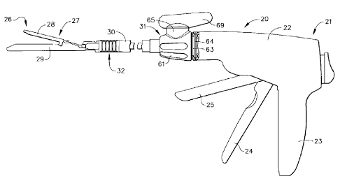
The component parts of the articulation transmission assembly 31 are
illustrated in Figure 3. The major components of the: assembly are an actuator
37, an
articulation body 38 and a nozzle 39. Rotaxional movement of the actuawr 37
causes
corresponding rotation of the articulation body 38 witlrirt the nozzle 39. The
first and
second elongated transmission band assemblies, 35 ~tnd 36, consequently
reciprocate
axially in opposite directions parallel to the longitudinal axis of the
endoscopic shaft 30
of the stapler to cause the remote articulation of the surgical fastening
assembly
through the flexible neck assembly of the endoscopic ahaft.
Referring specifically to Figure 3 in combination with Figures 6-8, a detailed
illustration of the articulation body 38 is provided. The articulation body
has a deck
40 consisting of first and second spaced-apart, semi~;,ircular deck halves, 41
and 42.
The deck halves are mutually opposed to each other and essentially represent
mirror
images of each other. The first and second deck halves have protruding from
their
surfaces mutually opposed first and second detests, 43 and 44. Each deck half
has a
set of deck teeth 45 spaced about 180° from the set of deck teeth on
the other deck
half.
The articulation body also has a generally ciircular base 4b. The base has a
pair of rotation stops 47 descending from its surface ass well as a pair of
finger recesses
48. The base 46 flexibly supports the deck 40 on two sets of beams. First
inner and
outer flexible beams, 49 and 50; extend upwardly from the base and are
integrally
atxached to the first deck half 4I . Likewise, second inner and outer flexible
beams, S I
and 52, extend upwardly from the base and are integrally attached to the
second deck
CA 02217079 1997-09-26
- 16-
half 42. The first and second outer flexible beams, and the first and second
inner
flexible beams, are displayed in mutually opposed relationship.
Again focusing on Figure 3 and Figures 6-8, the articulation body 38 further
includes a drive gear 53 descending from the base 46. The drive gear has a
flared
opening 54 through it, and a lower pivot 55. Within the flared opening of the
drive
gear, there is a firing rod orifice 56 for receiving the firing rod 57
enabling the firing
of staples into the clamped tissue in response to pivotal rotation of the
firing trigger
(see Figure 12). Coring cavities 58 are embedded in the base for manufacturing
optimization. The drive gear is coupled to first and second drive racks, 59
and 60, on
the flexible elongated transmission band assemblies, 35 and 36, to effect the
desired
reciprocating movement of the bands.
The nozzle 39 of the articulation transmission assembly is specifically
illustrated in Figure 3 in combination with Figures 9 and 10. The nozzle has a
nozzle
body 61. The nozzle body has an axial bore 62 extending through it for
receiving the
drive gear 53 of the articulation body 38. The bore provides a continuous
opening
axially from the frame into the elongated endoscopic shaft, and therefore the
firing rod
57 and other operative components of the stapler can communicate with the
surgical
fastening assembly 27 from the frame 22. The nozzle body also has a frame
groove
63 and flange 64 to fasten the body of the articulation transmission assembly
to the
frame (see Figure 1).
Extending from the nozzle body 61 of the nozzle 39 is a decent housing 65.
Within the housing, there is an annular array of detent teeth 66. Spaced from
the
detent teeth is a detent housing floor 67. The floor 67 is displayed adjacent
to the
nozzle body 61. It has a pair of ledges 78 which interact within the rotation
stops 47
of the articulation body to limit the degree of rotation. When the
articulation body is
inserted into the detent housing, the base of the articulation body sits on
the floor
within the detent housing, and the deck teeth 45 of the first and second deck
halves, 41
END-350
CA 02217079 1997-09-26
- 17-
and 42, of the deck 40 are aligned with the detent teeth 66 of the detent
housing to
provide an essentially continuous surface. Additionally, when the articulation
body is
inserted, the lower pivot 55 of the drive gear 53 is received in a pivot hole
68 located
interiorly within the nozzle body adjacent to the axial bore 62 (see Figure
12).
Figure 3 in combination with Figures 4 and 5 illustrate the actuator 37 of the
articulation transmission assembly. The actuator consists of a lever arm 69, a
circular
cap 70 and a pair of retaining fingers 71. The lever arm is mounted on the top
of the
cap. The pair of retaining fingers descend downwardly from the underside of
the cap.
Each of the retaining fingers has a retaining clip 72. The retaining fingers
are
received within the finger recesses 48 of the articulation body 38. The
underside of
the cap (Figure 5) has a slot depression 73 embedded within the cap. The slot
depression is bounded by a pair of parallel slot walls 74 and diagonal flats
75.
Pressure points 76 are consequently provided at the junction between the
parallel walls
and the diagonal flats.
The first and second detents, 43 and 44, of the deck halves of the
articulation
body are inserted into the slot depression 73 within the underside of the
circular cap
70. Accordingly, the parallel slot walls 74 frictionally contact the first and
second
detents of the deck, thus securing the actuator 37 to the articulation body
38. Further,
when the articulation body is inserted into the detent housing 65 of the
nozzle body 61
so that the articulation body is retained when the firing rod 57 is received
through the
firing rod orifice 56 of the drive gear 53, the cap 70 is secured onto the
detent housing
when the cap rests on an actuator cap lid 77 of the detent housing.
Advantageously, each of the three significant components of the articulation
transmission assembly, namely the actuator, articulation body and nozzle, are
injection
molded components. The preferred material of construction for each of the
components is a glass fiber-reinforced amorphous polyamide, sold commercially
under
END-350
CA 02217079 2005-04-27
-I8_
the trade name Grivory GV-4H by EMS - American Griloh as of the date upon
which
the applicarion which matured into this patent was filed.
Referring now to Figures I1 and 12, there is shown the articulation
S transmission assembly 31 of the stapler ZO when the assembly is in a Locked
position.
IO
In this locked position, the deck teeth 45 of the articulation body 38 are
matingly
coupled to, and mesh with, the detest teeth 66 of the detest housing 65. This
engagement of the deck and decent teeth fixes the at~iculation position of the
surgical
fastening assembly 27 of the stapler. The slot deprE;ssion 73 within the
underside of
the cap 70 of the actuator 37 frictionalIy receives thE; first and second
detests, 43 and
44, of the deck 40.
Referring now to Figures 13 and 14, there is shown the articulation
transmission assembly in an unlocked position. In the unlocked position, the
deck
teeth are decoupled and disengaged from the decent teeth. The unlocked
positions of
the articulation transmission assembly are spaced between the locked positions
of the
assembly. When a rotational farce is applied to the lever arm 69 of the cap
70, the
pressure points 76 at the junction between the diagonal flats 75 and the
parallel slot
walls 74 urge the first and second detests, 43 and 4<~, of the deck toward
each other.
As the detests are urged toward each other, the first and second deck halves,
41 and
42, of the deck are effectively compressed toward each other to enable the
withdrawal
of the deck teeth from engagement with the decent teeth within the detest
housing of
the nozzle. When the deck and decent teeth are withdrawn and decoupled from
each
other, each tooth on the sets of deck teeth will snap into engagement with a
respective
tooth on the array of detest teeth unless additional rotational force is
applied to the
lever arm of the actuator. If additional force is applied, the pressure points
within the
slot depression of the cap will continue to urge the dexk halves toward each
other, and
ratcheting rotation will occur and continue until the rotational force is
released.
CA 02217079 1997-09-26
- 19-
Accordingly, ratcheting rotation of the articulation transmission assembly is
provided, correspondingly causing articulation of the surgical fastening
assembly in a
plurality of discrete positions angled from the longitudinal axis of the
endoscopic shaft
of the stapler. The compression of the deck in response to rotational movement
of the
lever reduces the force the user must apply to articulate the surgical
fastening assembly
relative to the force which must be overcome to cause an articulation of the
surgical
fastening assembly when pressure is appiied directly to the surgical fastening
assembly.
Furthermore, when the articulation body 38 is rotated in a first direction in
response to rotational movement of the actuator 37 to cause articulation of
the surgical
fastening assembly in that first direction, a rotational position will be
reached where
the rotational stops 47 of the base 46 of the articulation body abut the pair
of ledges 78
protruding from the floor 67 of the decent housing 65. Consequently, further
rotational movement of the articulation body in the first direction, and
further
articulation of the surgical fastening assembly in that first direction, is
prevented.
Consequently, the interaction of the rotation stops with the pair of ledges on
the floor
of the detent housing acts to limit the degree of rotational movement of the
articulation
body, and thus the degree of articulation of the surgical fastening assembly
of the
stapler.
Referring now to Figures 15-21 and 23, the details of the preferred
transmission band assemblies are illustrated. The first and second
transmission band
assemblies, 35 and 36, have first and second transmission bands, 80 and 81,
respectively. Each transmission band has an elongated structural portion, 82
and 83.
When the bands are brought into contact with each other during assembly of the
instrument, they form an elongated cylinder which has a longitudinal cavity
150
through it concentrically positioned between the bands for the passage of the
firing
rod, 57 (see Figure 12). The first and second structural portions of the
transmission
bands have stiffening ribs, 84 and 85, to enhance structural support. At the
proximal
END-350
CA 02217079 2005-04-27
-20-
ends of the first and second bands, there are displayed the first and second
racks, 59
and 60, which mate with the gear of the articulation uansmission assembly. As
discussed above, rotation of the gear converts the rotational movement of the
articulation transmission assembly into longitudinal movement of the
transmission
band assemblies for articulation of the end effector.
The first and second transmission bands have exterior reinforcement band .
portions, 86 and 87, respectively, extending distally from the suuctural
portions of the
bands. Each exterior reinforcement band portion has a plurality of attachment
lugs 88
for securing first and second interior articulation bands, 89 and 90. The
transmission
bands are preferably composed of a plastic, espExially a glass fiber-
reinforced
amorphous polyamide, sold commercially under the trade name Grivory GV-5H by
EMS-American Grilon. In contrast, it is desired that the interior articulation
bands of
the transmission band assembly be composed of a meal, advantageously full hard
301
stainless steel or its equivalent. The attachment lugs on the exterior
reinforcement
band portions of the transmission bands are received into and secured within a
plurality of lug holes 91 on the corresponding interior articulation band.
At the distal end of the first and second interior articulation bands, there
are
first and second connector loops, 92 and 93, to couple the bands to the
cartridge
channel 29 (see Figures 24-26).
The remaining details of the preferred flexible neck assembly of the stapling
instrument of this invention are shown in Figures ~ and 24-27. The flexible
neck
assembly is preferably composed of a rigid thermo-plastic polyurethane sold
commercially as ISOPLAST grade 2510 by the Dow Chemical Company. The
flexible neck assembly 32 has the first and second flexible neck portions, 33
and 34.
These neck portions are separated by a central Iongiaidinal rib 94. The neck
portions
each nave a plurality of neck ribs 95 configured essentially as semi-circular
disks.
Each neck rib has an interior plate 96 which is substantially perpendicular to
the
CA 02217079 1997-09-26
-21 -
central longitudinal rib and parallel to an adjacent interior plate. Each neck
rib also
has a concave exterior dish 97 extending from its interior plate. As such, the
flexible
neck portions together generally form a cylindrical configuration. Separating
the neck
ribs are a plurality of kerfs 98. A side slot 99 extends through each of the
neck ribs to
provide a passage through the first and second flexible neck portions for
receiving the
interior articulation bands and exterior reinforcement band portions of the
flexible
bands. In a similar fashion, the central longitudinal rib separating the first
and second
flexible neck portions has a central longitudinal slot 100 for providing a
passage to
receive the stapler actuating members and if desired, a knife blade for
cutting the
tissue between the staple lines during or after firing.
Extending proximally from the first and second flexible neck portions, there
are first and second support guide surfaces, 101 and 102, for supporting the
reciprocating movement of the interior articulation bands and the exterior
reinforcement portions of the flexible transmission band assemblies. Extending
from
the distal end of the flexible neck portions, there is a channel guide 103 for
properly
guiding the movement of the stapler actuating members into the staple carnidge
of the
stapling instrument.
As shown nicely in Figure 22. when the flexible neck assembly is fully
articulated, adjacent concave dishes 97 come into contact with each other. The
spacing between adjacent dishes, and the size of each dish chosen, can provide
a
practical means for controlling the degree of articulation and the total
amount of
articulation achieved. In addition, the optimization of the design variables
of the
flexible neck assembly enables one of the transmission band assemblies to take
a
substantial load under compression during articulation while the other band
assembly
is concurrently taking a load under tension.
The proximal end of the cartridge channel (illustrated in Figure 24) has a
pair
of band connector ears, 104 and 105. These band connector ears are inserted
into and
END-350
CA 02217079 1997-09-26
-22-
through the connector loops, 92 and 93, respectively, on the distal end of the
interior
articulation bands. In this manner, the carnidge channel which houses the
staple
caraidge is coupled to the interior articulation bands of the flexible neck
assembly.
Figure 28a and 28b illustrates how the flexible neck assembly provides for the
articulation of the end effector of the stapling instrument. Specifically, the
reciprocation of the first and second flexible transmission band assemblies in
opposite
directions causes the interior articulation bands received into and through
the side
slots of the neck ribs on the flexible neck portions to reciprocate in a like
manner.
Upon reciprocation of the interior articulation bands, in particular when the
first band
is moved proximally in tandem with the second band moving distally as
illustrated in
Figure 28, the first and second flexible neck portions bend as the neck ribs
of the first
flexible neck portion move toward each other and the neck ribs of the second
flexible
neck rib portion concurrently move away from each other. The coupling of the
interior articulation band to the exterior reinforcement band portion of the
transmission
band prevents the interior articulation band from buckling between adjacent
neck ribs.
Although this invention has been described in connection with its most
preferred embodiment, numerous additional embodiments will become readily
apparent to those skilled in the art. For example, although the invention has
been
described in connection with an articulating endoscopic stapler, the invention
is equally
applicable to conventional open surgical instruments. Additionally, although
the
invention has been described in connection with an articulation transmission
assembly
and flexible neck assembly which provides for remote a.~ticulation of a
surgical
fastening assembly, it is equally applicable to an instrument which provides
remote
articulation of a different kind of end effector. Accordingly, the preferred
embodiment described in connection with this detailed description is intended
to
illustrate the invention only, and is not in any way intended to limit the
scope or spirit
of the claimed invention.
END-350