Note: Descriptions are shown in the official language in which they were submitted.
~ CA 022174~2 1997-10-03
~ ~.
.~L,~T~
~ T~A';~LbTI~I
Docket No.: 67190/953266
Description
PEM fuel cell
The invention relates to a fuel cell with a
proton-conducting membrane, on which catalyst material and
a collector are arranged on both sides.
Fuel cells are used for electrochemical conversion
of chemical energy, in particular in the form of gaseous
hydrogen and oxygen, into electrical energy. Of the large
number of known types, so-called PEM fuel cells ~PEM =
polymer-electrolyte membrane) are preferred, for example for
mobile use. The advantages of fuel cells of this type reside
in a comparatively low operating temperature (up to about
100~C), in the absence of a corro-sive liquid electrolyte,
in the stability with respect to carbon dioxide (CO2) and,
finally, in a relatively simple mechanical structure. In
addition to the cell housing, cooling units or separators,
gas supply or distribution means and means for constructing
fuel cell stacks from individual elements, PEM fuel cells
actually consist essentially of two gas-permeable, porous,
electrically conductive collectors on the anode and cathode
sides, which are next to the solid-electrolyte membrane.
Between the collector and the membrane, there is
in each case a catalyst in finely divided, catalytically
active form, for example platinum or a platinum alloy. One
side of the fuel cell is supplied with a combustible gas in
particular hydrogen or a hydrogen-containing gas, and the
other side is supplied with an oxidant, in particular oxygen
or an oxygen-containing gas, such as air. Hydrogen is
oxidized at the anode, protons being produced which diffuse
through the membrane to the oxygen side; in this case, water
is generally entrained with them (so-called drag effect).
At the cathode, the protons recombine with reduced oxygen to
form water, referred to as product water, which is removed
in suitable fashion from the fuel cell.
CA 022174~2 1997-10-03
Through the drag effect, water is drawn from the
anode side of the membrane, so that this side dries out and
therefore loses its function if not enough water is added.
Further problems are the high costs for production of the
membrane, and the lack of cost-efficient processes for
producing membrane/electrode units with a low level of
catalyst coating and high power density, in particular for
operation with air at close to atmospheric pressure.
Indeed, for relatively thick membranes, the ohmic losses
have a power-reducing effect.
Technical solutions for fuel cells are already
known (see, for example, DE-A 33 21 984 and EP-A 0 560 295).
The gas-permeable, electron-conducting layers, that is to
say collectors, used in this case are carbon paper (US-A 4
215 183) and carbon fabric ("J. Appl. Electrochem.", Volume
22 (1992), pages 1 to 7); metal structures may also be
considered ( DE-A 42 06 490). The proton-conducting
membranes used are perfluorinated sulfonated polymers such
as nafion, raymion and permion ("Ber. Bunsenges. Phys.
Chem.", Volume 94 (1990), pages 1008 to 1014). For the sake
of convenience, the layer thickness of the membranes is
between 50 and 200 ~m. Important properties of the
membranes are heat-resistance (up to about 100~C), reduction
and oxidation stability, resistance to acid and hydrolysis,
sufficiently low electrical resistivity (~ lO n cm) with ion
conduction (H+) at the same time, low hydrogen or oxygen
permeation and freedom from pin-holes. At the same time,
the membranes should be as hydrophilic as possible in order,
through the presence of water, both to ensure proton
conduction and (by reversed diffusion of water to the anode)
to prevent the membrane from drying out and therefore to
prevent a reduction in the electrical conductivity. In
general, properties of this type are achieved with materials
which have no aliphatic hydrogen-carbon bonds, which, for
example, is achieved by replacing hydrogen by fluorine or by
the presence of aromatic structures; the proton conduction
results from the incorporation of sulfonic acid groups (high
acid strength).
' CA 022174~2 1997-10-03
~ . .
The electrodes, that is to say the catalyst layers
arranged between the collectors and the proton-conducting
membrane are essential for correct operation of a fuel cell.
On these layers, which consist of very finely divided
catalyst material which, for example, may be applied to
carbon, the fundamental processes take place, namely
adsorption, dissociation and oxidation of hydrogen on the
anode side, or the corresponding reduction of oxygen on the
cathode side. The layers must have sufficient gas
permeability and catalytic activity, that is to say a large
internal surface area, the intention being for the amount of
catalyst, for example platinum, to be as small as possible
for economic reasons. As an example, fuel-cell electrodes
currently require amounts of platinum o~ between 3 mg/cm2
(EP-A 0,560,295) and 0.095 mg/cm2 (EP-A 0,569,062) or 0.07
mg/cm2 ("J. Electrochem. Soc.", Volume 139 (1992), pages L28
to L30). In order to ensure intimate contact between the
collector, electrode (= catalyst) and membrane, the layers
are usually compressed at high temperature. The housings of
the individual fuel cells are configured in such a way that
a good gas supply is ensured, and at the same time the
product water can be discharged properly. In order to
obtain sufficient power, fuel cells are usually joined to
form stacks, the requirements which have been mentioned
being met through the design.
Although it is actually known to achieve internal
wetting through thin membranes (WO 92/13365), this is
limited by the minimum handlable layer thickness (~ 50 ~m).
In addition, it is already known (US-A 5,242,764) to apply
thin membranes (~ 20 ~m) by wet chemical means to
electrodes, and subsequently compress them (total thickness
~ 40 ~m). However, this procedure is restricted because of
the wet chemical method, for example in terms of layer
thickness and material losses in the process, and, in
addition, there is no indicated solution as to how the
requirements for planarity on the collector surface, in
particular for relatively thin membranes, can be met.
Furthermore, the electrode which is used has a platinum
' ~ CA 022174~2 1997-10-03
~ ~.
-4-
coating level of l mg/cm2 and is therefore a long way from
meeting the requirements in terms of high power density and
low cost. In addition, the membrane/electrode unit is
sealed at the edge by a membrane, having a central opening,
which overlaps this unit. However, this is very difficult
and intricate to carry out, because the sealing membrane
must likewise be very thin; furthermore, gradation of the
membrane is very expensive.
Yet other problems can occur with current tech-
nology. Thus, for example, collectors made of graphite paper
or carbon fabric, even when they are compressed at high
pressure, sometimes only have point contact with the
catalyst material. It then becomes difficult for the
electrons to flow from the electrode to the collector. The
membranes are currently produced using conventional wet
chemical methods (polymerization, sulfonation), but this
necessarily leads to waste disposal problems and to
environmental pollution.
The object of the invention is to design a fuel
cell with a proton-conducting membrane, on which catalyst
material and a collector are arranged on both sides, in such
a way that, on the one hand, the internal resistance of the
membrane is reduced and the fuel side is prevented from
drying out, and, on the other hand, economic production of
the membrane is possible.
This is achieved according to the invention in
that on the side facing the membrane, the collectors are
provided with an electrically conductive gas-permeable
carbon aerogel with a surface roughness of c 2 ~m, a
catalyst layer of platinum or a platinum alloy is in each
case applied to the carbon aerogel by material bonding,and
a membrane, deposited by plasma-chemical means, with a layer
thickness of between 3 and 50 ~m, is located between the
catalyst layers.
One essential feature of the fuel cell according
40' to the invention, which can be referred to as a "thin-layer
fuel cell", is the carbon aerogel. This material, which is
known per se (in this regard, see, for example: "J. Appl.
' CA 022174~2 1997-10-03
,
Phys.", Volume 73 (1993), pages 581 to 584) is applied to a
collector, using a suitable method. The collector
preferably consists of graphite paper or carbon fabric and
is advantageously rendered hydrophobic, for example with
polytetrafluoroethylene.
The carbon aerogel preferably has an electrical
conductivity of between 10-2 and 103 Q~1-cm~1 and a density of
between 0.06 and 0.7 g/cm3; the pore size is between 20 and
100 nm (porosity up to about 95 ~). The hydrophobicity of
the carbon aerogel can be set by selecting the starting
monomers and through process control, as well as by a
corresponding secondary treatment. The essential object of
the carbon aerogel consists in producing substantial local
planarization (roughness c 2 ~m) of the very uneven surface
structure of graphite paper and carbon fabric. On the one
hand, this permits intimate contact between the collector
and the catalyst material and, on the other hand, the carbon
aerogel represents a substrate which has sufficient
planarity to make it possible to deposit a relatively thin
membrane by plasma-chemical means.
The catalyst is applied in a thin layer to the
carbon aerogel. This is advantageously done using a plasma-
chemical process, platinum being deposited in a thin porous
layer in a plasma deposition reactor, for example in a low-
pressure plasma between 10-4 and 10 mbar, from an organic
platinum compound which is gaseous at these pressures, for
example trimethylcyclopentadienylplatinum; the excitation
can take place using radio-frequency, microwaves or an ECR
transmitter (ECR = electron cyclotron resonance). Layers of
this type have an electrical resistivity of < 1 mQ cm, for
example a resistivity of about 20 ~Q cm. As an alternative,
however, sputtering methods and other deposition methods can
be used for producing the platinum layers (in this regard,
see: "J. Electrochem. Soc.", Volume 139 (1992), pages L28 to
L30).
40' The catalyst layer is arranged on the proton-
conducting membrane, which has a layer thickness of between
3 and 50 ~m, preferably between 5 and 20 ~m. This membrane,
CA 022174~2 1997-10-03
which is produced using a plasma polymerization process,
preferably has an electrical resistivity of ~ lO Q-cm when
it is in the wet state. The plasma-chemical deposition
advantageously takes place in a low-pressure plasma, between
10-4 and 10 mbar, excited by radio-frequency, microwaves or
an ECR transmitter, using monomers which are gaseous at
these pressures. Suitable monomers are, for example,
perfluorinated compounds, for example octafluorocyclobutane
and perfluorobenzene, or even monomers with C-H bonds which,
in the plasma polymer, do not form any aliphatic H atoms
which could constitute attack sites for oxidative breakdown.
The proton-conducting property of the membrane is achieved
by adding suitable gases to the process gas, for example SO2,
S03, trifluoromethanesulfonic acid or the fluoride thereof,
strongly acidic carboxylic acids, for example
trifluoroacetic acid, and volatile phosphoric acid compounds
(in this regard, see: "Ber. Bunsenges. Phys. Chem.", Volume
98 (1994), pages 631 to 635).
The processes of the plasma deposition of catalyst
and membrane may partially take place at the same time. In
this way, it is possible to effect intimate combination of
the catalyst and proton-conducting polymer (ionomer) over
the electrode regions next to the membrane. Because of the
low coating level (for example about O.1 mg Pt/cm2), the
pores between the catalyst particles may in this case be
fully or partly filled with ionomer.
A further catalyst layer is arranged on the
proton-conducting membrane. This layer may likewise be
deposited directly on the membrane by plasma-chemical means,
but may also be applied using other techniques. After this,
the second collector is arranged on this catalyst layer,
this collector generally consisting of the same material as
the first collector, and the entire arrangement is then
compressed.
' ~ CA 022174~2 1997-10-03
~ .
-7--
As an alternative, a complete planar arrangement,
consisting of catalyst material and collector, may be
pressed onto the membrane in order to produce the fuel cell.
Here again, a prerequisite is sufficient planarity for
obtaining a good contact, which is achieved by a layer of
carbon aerogel. A further production possibility consists
in likewise depositing a membrane on the second electrode,
and then forming the thin-layer fuel cell from the two
identically constructed components using a joining process,
for example by pressing. This greatly reduces the risk of
pin-holes.
A joining layout in which the two collectors are
of different size is advantageous for the construction of
the fuel cell according to the invention. Indeed, this
allows a gas-tight electrically insulating connection
between the anode and cathode spaces. Sealing of this type
is possible both with a conventional cell design, as
disclosed, for example, by DE-A 33 21 984, and with an
innovative approach, which constitutes the subject-matter of
German Patent Application Akt.Z. P 44 42 285.7
("Brennstoffzellen und daraus hergestellte Batterien") tFuel
cells and batteries produced therefrom]).
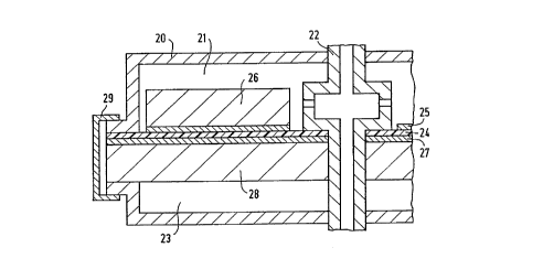
Figure 1 represents the joining method for the
membrane/electrode unit of a known fuel cell with air
operation. In this case, an additional sealant is used,
which need not consist of the membrane material and, for
example, may also enclose the entire periphery of the
membrane/electrode unit. Figure 2 shows the joining method
for the cell design of the above-mentioned innovative fuel
cell.
In Figures 1 and 2, the indicated reference
numbers have the following meaning:
10, 20: cell housing
11, 21: hydrogen gas space
12, 22: gas tube
13, 23: air/gas space
14, 24: membrane
15, 25: anode
CA 022174~2 1997-10-03
16, 26: collector
17, 27; cathode
18, 28 collector
19: seal
29: clamp
The structure of the fuel cell according to the
invention solves as follows the problems which arise with
conventional fuel cells:
- the small layer thickness results in a small layer
resistance and a higher reverse diffusion of water,
that is to say the membrane does not dry out;
- because of the smooth carbon aerogel layer, intimate
contact between the electrode/membrane unit and the
collector is possible;
- the low level of catalyst coating results in a more
economical production process;
- the production method is environmentally friendly since
vacuum processes are employed.