Note: Descriptions are shown in the official language in which they were submitted.
CA 02217489 1997-10-03
W O96/31322 PCT/~5G~
LIGHT PROJECTION APPARATUS
BACKGROUND OF T~l~; IlWENTION
THIS invention relates to a light projection apparatus, in particular for
projecting an illnmin~t~ line onto a workpiece.
In a number of industries, for e~ample, timber sawmills, stone masonry, the
textile industry, etc., frequently a requirement is to saw, grind or cut the
products concerned along straight lines which may be of considerable
lengths, sometimes up to 12 metres or more.
The conventional methods of guiding the cutting m~hin~ory involved include
the use of chalk lines, strips, straight edge rules and so forth. These
methods are clumsy, ~iifficlllt to apply and are easily rii~p!~cecl by the
operations in progress.
More l~ce,llly, the use of lasers projecting a long, th;n line of light on the
workpiece have come into use. This system ~ esc~ a major i---~lo~ ent
over t_e older conv~nti~ n~l methods. However, a disadvantage of existing
laser systems, particularly where very long lines are required, is that the
intensity of the light becomes greatly reduced towards the far end of the
projected line, and this, combined with the unavoidable small angle of
incicl~n~e of the beam on to the workpiece at the far area, makes it difficult
to distinguish the line clearly.
The known art utilizes a lens system comprising a solid cylindrical glass rod
to fan out the rays of a laser beam to produce a line of laser light on the
surface of the object when the bearn is projected on to such object.
SUBSTITUTE SH EET tRULE 26)
-
~ CA 02217489 1997-10-03
.
r,l Figure 1, curve Cl shows the co~ aLive i~rerlsities of the light
produced by this system at dif~elent augles t m~ni~*ng frorn th~ light source~
As can be seen, the intensity is greatest over the centr e poruon o~ t~e beam
(at x), ~,i-h~lly reducing to zero ~owards the outer ends of the be~m.
Figure 2 shows a typical layout of arl a~Tangement for projeci~ng a lirle of
light .~B, from laser 1, on to a workpiece. Curve C2 shows tne co",~ Ltive
br;ghtn~ resulting at ~ianous points along this iine As can be seen, bright
illumina~on is provided on the por~ion of the line ~earer to the light source,
~hiIe o~ rhe portion fi~rther from thc source the level of ilTllmin;i~on is
substantially lower. This is accounted for by a combination of factors, each
of vr_ich m~t~ri~lly contributes to this iin~aticfa~tory sitil~ti~n
These factors are:
1) The ~reater dista~lce from the light source.
2) The co~dL~veLy lower inrerlsity of light em~in~tin~ ~om the lens
~ll the outer portion of the beam.
3) The very obLiq~e angle at ~hich thc Iight strLlces the surface of the
wor~ plece at this end of the line~ rP~llltin~ in an already reduced
relati~e light i~tensity bemg spread o~rer a long le~gth of the line
A device Som~tiiTies empIoyed to improve this resuLt is to offset the solid
cyl;n~ric~i1 lens from the centre line of the laser beam This results in a
Iligher proportion of light being projected from the le~s to one side of the
beam as compared with the other side Cwe D in Figure 1 illustrates the
A~N~)~D SHEE~
CA 02217489 1997-10-03
.
compar~tive light i~tensities obP~ned with such a prior ar~ de~ice in Which
che beai~ from the lighc source is offset from the ~is of the lens used to
deflect that beam onto the wor~ surface. This effect is utiLised to incr~asP ~o
som~ ext~ the proportion of Light trqncmitred to the more dis~ant portion
of the lin~ Howe~er, even with ~chis modificariorL, th~ variation in
illuminatior~ of the Line from one end to the othe~ is con~ide~abLe.
D}~ ~3 20 11~ ~is~los~s a li~ht projection apparatus which is used to project
all ilItlminat~d line onto a surface. lhe disclosed qpparatus utïLises a laser
source to emit7ina a laser b~am. A specially shaped pcisrn receives the
emicced laser beam a~d refrac~s il in such a way as ~o prod~ce a fan~ed
~e3m which forms a li~ of li~ht on the surface. There is a genera y
constan~ ~te~sity of il1~minqrjo~ In the lille of light.
Apart ~om ~he difficulries of m~nlt~actunn~ the specially shape~ prism to
achieve the desired re~action, the disclosed ~L)~L~L~s h~s the disadvan~age
that i~ the fan;led laser beam is projected symm~rt~rqlly onto the surrac~
abou~ an axis at right a~gles to dle surface This mak_s i~ unsui~able for
proje~i~a rather long il Tnin~t~i lines on~o dle surface, because d~e longer
the line, the fhr~ber away from rhe su~face the laser projection appararus
mus~ be sin~t~
OB.JECT OF l~; l:?~VE~IIO~
lt is an object of the irlYeutiQrl to provide a systçm i~ which a l~e of laser
light may be projected on to a surface ~ tl~f~ obliquely r~lative to the light
sourc_, such a line of light bc~g s~lbst~nn~lly cverlly illl~min~r~d throughou~
its le~gth, and thus more easily visible at all pOiIltS alorlg ;ts length.
O~D SWET
,
~C~ . ~ <).~: ~P.~ C~ , - CA 02217489 1997-10-03,
8UM~LRY ~ TNE lNV~ION
Accordins to the present inventicn, there is prcvided
a light projection apparatus ~or prajecting an illu~inate~
line ont~ a sur~ce, the apparatus comprising:
a laser source ~or e~ittin~ a laser bea~, an~
optical lens means which is arranged to receive the
emitted laser bea~ and to project, onto the surf~c~, a work
light beam having a ~anned planar con~iguration which will
be visi~le as a straight line on the surEace, thereby to
~o~n an iiluminated line c~n the surfa~e, characterised in
that:
the laser source ~nd optical ~ens means are arranged
su~h th~t the w4r~ing laser beam is projected obliquely
onto the ~urface to form an illumin~t~d line extendin~ from
a near position close to the opti~al lens means to a ~ar
position remote ~rom the optical lens means, and
the optical lens means comprisPs a cylindrical hollow
lens having internal and external surf~c~s, the arrangement
o~ the in~ernal a~d cxternal ~ur~ace~ ~eing such that the
optical lens me~ns both refracts and ref~ects ~he emitted
laser bea~ to produc~ a wor~ing laser beam which has hi~her
light intensi~y in portions of the beam which are projeeted
ant~ the surfac2 towards the far poslticn than in portions
af the heam which are projec~sd onto the ~ur~ac~ tow~ds
the ne~r position, where~y the illuminated line has
generally e~ual illumination along its leng~h between the
near and ~ar positions.
AUF~)Er) SHFFr
~ CA 02217489 1997-10-03
.
- 4a -
The o~tical lens is preferably con~igured so as to produc_
a work light beqm which increases in intensitv in a direction awav from ;he
Light be m de~lection means.
The Gptical lens pre~e~ably comprises
a Lens of generaLly cvlindric~l configur~tion having concentric concave and
conve.Y surr'aces, the lens being ad~pted to reflect and refract the emitted
beqm to produce the fanned ~vork light beam.
Tae lens is t~-picallv of a hollow, generally circul~ cyLincricaL configuration
w-hich is orientated such that its longitudinal aYis is substantiallv
perpendicular to the aYis of the emitted light be~rn.
In a preferred embodiment of the invention, the er~.ir.ed beam has a diameter
which is less than half the diameter of the lens, the errlitted beam impinging
on the lens to one side of the longitudinal aYiS of the lens.
The apparatus is typically mounted to a support rail. The appararus is
preferably able to move along the suppor~ rail and tilt relative to the support
rail in order to position the work line in a desired position and with a desiredangle of incidence relative to the surface.
The light source for emitting a light beam is usually a laser diode, although
Alll~Ho~ ~
CA 02217489 1997-10-03
a Helium-~eon plasma tube may al50 be used. ~erl a Helium-;~eon
plasma tube is used, an anarnorphic le~Ls is preferably positiarled between ~he
plasma tube and the light bearn deflecuon means in order to produce an
elliptic~ sh2ped wor~ beam.
BR~E~ DESC~ ON OF THE DR~W~GS
Fi~ure 1 shows the pattern of ligllt disi~bution of light produced by a
two prior art ~i~ht projection apparatuses;
Fi~ur~ 2 sho~s the typical layout of a prior art arrarLgemeIlt for
producillg a line on a w )r~iecP,
Figure; shovvs the patte n of lIght dis;~ib~tion emer~rLg from an
embodiment of the li~ht projecuon apparatus of the i~ve~tion
Flgur~ 4 shows Ihe a~rangcmcrLt of thc light projcc~dorl a~ t~s of the
i~ven~ion for pro~ in~ the pat~rrl of light Lrlt~n~ s Of
Figurc 3;
Figure ~ is a cross-section ~ievr of a pL~fc~led embodime~t of the
inYentiorl; a~
Figure 6 shows a p.i~c~ e vie~v of an apparaols according to the
illven~on.
~ )E~ S~EET
CA 02217489 1997-10-03
DESCRUPIIO ~ OF .4~ E~rBO Dr~nF~r
A mesns whereby -he psttern of Lig;ht dis,~ributiorl emer~in6 from the optical
system may be changed from the symmetncal par~e.~n of a conventio~l
s,vs~em to a pattem of the ~pe described above is desc~ibed be~ow.
'ln Fi rure 3, curve G1 shows diagr~mm~ lly the pat.~rn of li~ht
dis~lbuiotl emergi~g from a Iight projection apparatus of the in~cr~tion. As
can be seer~, the int~nsity of he liCht is Oreatest ne~r a~ edge of the beam
at a fairly iarge dista~ce from the centre of tb,e beam (at y).
Referrinc to Figure 4, the i~ of light emerging from the optical syslem
Of ~ the in~entiorL is highly rnn~.~"t, ~d in the upper poItion of the beam (at
E), ~ailinG off more or less exponeniaLl~r to the much Lower intensiy in the
lower portion of the beam (at F). The result is that a s~lbst~n~i~l amoun~ of
light is pro~ected o~ to the far portion of the li~c towards the end B.
Ihe combi~ation of the5e fac~ors resuIts in the lirLe of liaht AB beina more
or less e~enly iIll.r.l;ll~ i along its f~ll ler~eh, as illustratcd in curve G2.
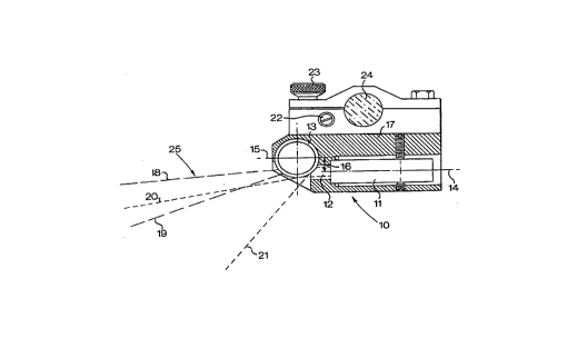
Referring to Figure 5, a light projectioll app~ratus 10 comprises a lascr diode
module 1 I which shines a bearn of Iaser light 12 on to a hollo~r cylinl1ri~
lens 13. The centre line 14 of thc las~ bcarn 12 is spaced fiom the centre
line 15 of the Iens 13 by arl off-set distance 16. The beam 12 is refrac~ed
and re~ected iDto a fa~ed configuration. The refracted rays are produced
nearer the centre line 15 of the lens between the illustrative rays 18 aQd 19,
whslst, the reflected rays are produced fim:her away from ~he centre line 15
A~NO~Q S~tECT
- CA 02217489 1997-10-03
be~ve-n illusrrative rays 20 aIld 21. One point or intereSI in the curve
shown in Fi=,~re ~ is the poi~t H which depicts incre sed i~te~sity in the
~e~,ion v,here reflect~d and refracted Light omit~C from the light protecc~or~
appar~ms overlap.
The dioce module 11 should be orienta~ed so that the major ~xis of be~
is at right ancles to tho axis of lens 13, and the off3e~ dis~Lnce 16 may
pref_rably be such t~at the iower limit of beam 12 does not pass ~Le lower
surface of Lens l,.
Thc ef.ect of usirL~ a hollow cylin~ric~l le~s 13 off-set from the laser beam
12 is that the refracted rays emerging from nearer the centre lirlc OI thc le2s
are closely spaced radially, while those emerg~g fiIrther away are
?rogres,ivley mcre wide~y spaced radially.
Inthe c~se of the reflected rays, those further from the ce~eli~e of le~s 13
are reflected less t~an those closer to ~e c~ntre I~n~o of the lerls. Reflec~on
occurs from both the exterr 1 and i~tcrnal 5~ 5 of the le~s. For this
reasou i~ is preferable to use a le~s without an anti-refl~ct;~n coating
T~he propor;iorl of light refiected is corLsiderably less thsn the propornon
refracted, but with suitable adjustrnent of the amount of offset of the Iens,
the intenser portion of ~ reflected rays overlap par~ of the less interlse
portion of ~e refracted rays, resul~rLg in a homoge~us li~e of light o~ the
workpiece, and providirlg a wider usable ang~llar spread of the beam.
rnls overlapping re~ec~ed portLoIl causes a slight increase i~ lighl ime~Lsily
over a small part of the intensity cur~te, as illdica~ed by the slight "hump" H
A~D~ S"~T
~ _ _ _ , ~ , _ ,
CA 02217489 1997-10-03
W 096/31322 PCTlGB~6rOOX~1
in the curve, the effect of which is not significant. (refer to Figure 3).
However, what is of considerable importance is the e~ctension of the curve,
which results in significant modification of the light distribution pattern on
the worlcpiece.
The pattem of light distribution thus obtained provides a near-ideal
distribution of light along the full length of the line, even where an
e~tremely long line relative to the height of the light source is required.
The pler~.lcd embodiment described a~ove employs a laser diode as the
light source.
It is also possible to employ a Helium-Neon plasma tube as the light source,
preferably in conjunction with an anamorphic lens positioned between the
laser and the hollow cylindrical lens to produce an eIliptical shaped beam.
A wide range of sizes of hollow cylindrical lenses may be used. It is also
possible to use other configurations of lenses and light reflection devices
such as curved mirrors or the like.
The use of hollow cylindrical lenses for the applications described above
eselll a simple means of achieving the required pattem of light
distribution.
It can be seen from Figure S that only a portion of the lens is ~ltili~e~7 Thus,if preferred, it is possible to incorporate just a segment of a hollow
SUBSTITUTE SH EET (RULE ~6)
-
CA 02217489 1997-10-03
W 096/31322 PCT/~5'
cylindrical lens into the device.
Hollow cylindrical lenses are in effect convex-concave lenses of which the
outer and inner radii have ~ common centre. It is also possible to use
convex/concave lenses of which the radii have separate centres.
The a~pa,dLus of the invention will preferably be mounted on a rail which
is aligned perpendicular to the plane of the work light beam and the
~pdldLus will be slidable along the rail so that the position of the beam
relative to a surface or workpiece can be varied. The rail is preferably
circular in cross-section and the ~a dLus may be rotatable on the rail.
The ay~aLdLus is also movable along the length of the rail so that the
min~te~7 line on the work surface can be positioned. In addition, fine
angular adj-l~tment of the beam is possible. That is, it will be possible to
adjust the angle of the beam relative to the axis of the rail by means of a
fine adj--ctment of the screw numbered 22 in the drawings. This will allow
the surface line to coincide with a required datum or other feature on the
work piece.
Figure 6 depicts a perspective view of the ~ualdLus in operation. The
d~pa~dLus includes a clamping screw 23 for clamping the a~ydldLus to the
rail 24. As previously mentioned, the ay~LLdLLls is rotatable on the rail 24
and is also slidable lengrthwise along the length of the rail. In addition, the
angle of the ~pdLdLus relative to the rail is adjustable by means of tne screw
22 so that the bearn 25 emitting from the apparatus can be angled relative
to the l-~ngit~ m, I axis of the rail. It is envisaged that the angle of
adj--~ment of the beam will be between 10~ and 15~.
SUBSTITUTE SHEET (RULE ;26)
' CA 02217489 1997-10-03
.
- 10 -
The apparatus of the inverltion is, on account of thc configuration of uhe
lens, able to illllmin~te a linc on a surrace at a posi~ion ~ar closcr to the
apparatus than has been possibie with prior a.-t deYices of this t~pe whtle still
providing ~ood iIIllm;n.~tion over the fi~l1 length of the worlcpiece surface.
Thus, it wiIl b~e noted, that the distarLce indicated by ~he letters A'-O' i~
Fi;~,ur_ ~' is l~ss than the distance A-0 depicted in Fi~ure 2. I~ p~ac~ce it Isfound t~at ~ith ~he li_ht projec~oin apparatus mou~ed about 1,2 m above
rhe surfac?, the distance A'-O' wil1 be a?proximately O.Sm whereas the
distance A-O of the pricr art arraL~ement is approximately ~m. l~is is
considered to be advantageous in applicalions where dlere are space
conrlnt~m~ont~ It is also a~lvanta~eous in that ~ere is a less acute angle of
]i~ht incidence on the surtace at the relevant position.
E~